1
Section 8
Switch
Status
Visual Status
Monitoring
Local and Remote Status Monitoring
You can keep track of the status of your Ring Switches at all times. To check the status of a
Ring Switch visually, you can monitor the Ring Switch’s indicator LEDs. To monitor the
status remotely, you can use Modbus over Ethernet (UDP). There is also an alarm output
that can be tied to a PLC or other supervisory device.
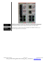
The status of your Ring Switches can be easily ascertained by simply looking at their LED
indicators. The LEDs can be used to quickly see the status or to locate a network problem.
See Section 2 for details on the LED indicators.
Port Status
(ACT/LNK LED)
After all Ethernet and/or fiber connections are made, check the LED’s corresponding to the
ports that each of the devices are connected to. Ensure that for each port that is in use, the
LED is on or blinking. If a port LED is off, go back and check for connectivity problems
between that port and the network device connected to that particular port. In addition, the
color of the LED should indicate the speed for which your device is connected at (yellow –
10Mbps, green – 100Mpbs).
Power & Switch
Status (OK LED)
The Ring Switch has an OK LED that indicates the power and operational status. It is ON
solid when there are no errors. It will go OFF if either power supply fails or a ring break is
detected. The OK LED will also flash if the switch is being “winked”, is in the boot-up
mode, or an internal error was detected.
Ring Status
(Ring LED)
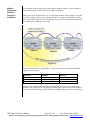
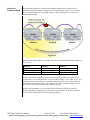
The Ring Switch has a Ring LED that indicates the status of your ring connections. It is ON
solid when all rings handled by the switch have continuous integrity. It will be blinking if
there is broken ring segment but all adjacent switches are responding. It will be OFF if the
switch is not configured for any rings. The ring LED will Blip (mostly OFF, with a quick
ON) when a configured ring has been broken and the break is local to one of the ports of the
switch. Typically the network with the fault will be between the two switches with Ring
LEDs in the Blip state. This makes tracking down faults quick and simple.
6RS Ring Switch User Manual
Page 21 of 30
Last Revised: 28-Aug-09
Sixnet Technology Park • 331 Ushers Road • Ballston Lake, NY 12019 • USA • +1-518-877-5173 • [email protected]