1
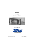
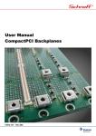
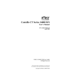
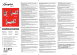
Hot Swap CompactPCI System GP/GS0808 User’s Guide # 095--20097-00 Rev A Copyright 2000 Doc No. 095-20097-00 Rev.A All Rights Reserved The information in this document is subject to change without prior notice in order to improve reliability, design, and function, and does not represent commitment on the part of the manufacturer. In no event will the manufacturer be liable for direct, indirect, special, incidental, or consequential damages, or the possibility of such damages, arising out of the use of this information. This document contains proprietary information protected by copyright. All rights are reserved. No part of this manual may be reproduced by any mechanical, electronic, or other means in any form without prior written permission of the manufacturer. Trademarks IBM PC is a registered trademark of International Business Machines Corporation. Intel and Pentium are registered trademarks of Intel Corporation. Award is a registered trademark of Award Software, Inc. Other product names mentioned herein are used for identification purposes only and may be trademarks and/or registered trademarks of their respective companies. Customer Service Worldwide Headquarters I-Bus Corporation 2391 Zanker Road #380 San Jose CA 95131, USA Tel: +(1) 408 428 6100 Fax: +(1) 408 428 6101 Toll Free: 877-777-IBUS Email: [email protected] European Headquarters I-Bus Unit 6, Chichester Business Park City Fields Way, Tangmere West Sussex, PO20 2LB, UK Tel: +44 (0) 1243 756300 Fax: +44 (0) 1243 756301 Email: [email protected] France, Italy I-Bus B.P 45 Valbonne 06901 Sophia Antipolis CEDEX France Tel: +33 (0) 493 004 360 Fax: +33 (0) 493 004 369 Email: [email protected] Other countries, contact [email protected] GP/GS0808 User’s Guide 3 Dear Customer, Thank you for purchasing an I-Bus Corporation product. We hope that this product exceeds your expectations. It is our desire to provide you with accurate, up-to-date information about the product(s) you have purchased. We welcome your comments and suggestions about our manuals. You may email those comments and suggestions to [email protected]. Please be sure to include your name, the name of your company, the product you purchased, and the manual number/revision (i.e. 00-00000-00 Rev. *). This number is located on the title page. At I-Bus Corporation, we value our customers and partners, and you can continue to count on I-Bus Corporation to be customer focused and to provide you a large range of solutions -- from cost-effective to fully customized industrial computer solutions. Again, thank you for your committment to I-Bus Corporation. We appreciate your business and look forward to continuing to work with you and helping you reach your goals. 4 C0406A User’s Guide Table of Contents Chapter 1. Introduction Introduction . . . . . . . . . . . . . . . . . . . . . . . . . . . . . . . . . . . . . . . . . . . . 1-1 Chapter 2. Specifications Enclosure . . . . . . . . . . . . . . . . . . . . . . . . . . . . . . . . . . . . . . . . . . . . . 2-1 Power Subsystem . . . . . . . . . . . . . . . . . . . . . . . . . . . . . . . . . . . . . . 2-2 Environmental . . . . . . . . . . . . . . . . . . . . . . . . . . . . . . . . . . . . . . . . . 2-2 Safety Agency . . . . . . . . . . . . . . . . . . . . . . . . . . . . . . . . . . . . . . . . . 2-3 Chapter 3. Hardware CPU Board . . . . . . . . . . . . . . . . . . . . . . . . . . . . . . . . . . . . . . . . . . . . 3-2 Add-in Boards . . . . . . . . . . . . . . . . . . . . . . . . . . . . . . . . . . . . . . . . . . 3-4 Rear I/O Transition Modules . . . . . . . . . . . . . . . . . . . . . . . . . . . . . 3-6 Backplane . . . . . . . . . . . . . . . . . . . . . . . . . . . . . . . . . . . . . . . . . . . . . 3-8 Backplane Cooling Fan . . . . . . . . . . . . . . . . . . . . . . . . . . . . . . . . . . 3-8 Chassis Filters . . . . . . . . . . . . . . . . . . . . . . . . . . . . . . . . . . . . . . . . . 3-9 Chapter 4. Power Distribution Power Supply . . . . . . . . . . . . . . . . . . . . . . . . . . . . . . . . . . . . . . . . . . 4-1 Chapter 5. Drive Bay Removing/Installing the Drives . . . . . . . . . . . . . . . . . . . . . . . . . . . 5-1 Chapter 6. Software Software . . . . . . . . . . . . . . . . . . . . . . . . . . . . . . . . . . . . . . . . . . . . . . 6-1 Appendix 1. Technical Reference P1 Connector Pin Assignments (System Slot) . . . . . . . . . . . . . A1-1 P1 Connector Pin Assignments (I/O Slot) . . . . . . . . . . . . . . . . . A1-2 P1 Signal Descriptions . . . . . . . . . . . . . . . . . . . . . . . . . . . . . . . . . A1-3 P2 Connector Pin Assignments (System Slot) . . . . . . . . . . . . . A1-5 P2 Connector Pin Assignments (I/O Slot) . . . . . . . . . . . . . . . . . A1-6 GP/GS 0808 User’s Guide 1 Table of Contents P2 Signal Descriptions . . . . . . . . . . . . . . . . . . . . . . . . . . . . . . . . . A1-7 P3, P4, P5 Connectors Pin Assignments (System Slot) . . . . . A1-7 P4 Connector Pin Assignments (Computer Telephony Bus) (I/O Slot) . . . . . . . . . . . . . . . . . . . . . . . . . . . . . . . . . . . . . . . A1-8 P4 Signal Descriptions (Computer Telephony Bus) (I/O Slot) A1-9 Appendix 2. Glossary of Terms Appendix 3. Limited Warranty Appendix 4. FCC Information 2 GP/GS 0808 User’s Guide Chapter 1 - Introduction Introduction Welcome to the I-Bus/Phoenix family of CompactPCI computer systems. This manual provides information necessary to set up and maintain your GP/GS 0808. The GP/GS 0808 System is a CompactPCI platform equipped with either an I-Bus/Phoenix Intel, or a Sun Microsystems Ultra Sparc single board computer (SBC). The system provides seven expansion slots in addition to the one slot or two slot SBC. The GP/GS 0808 is intended to meet the need for an entry level CompactPCI system for telecommunications, telephony, data communications, Internet, industrial or medical applications. The integrated enclosure houses a PICMG H.110 compliant backplane, redundant 400W power supplies, front accessible drive bays for three 5.25” half height and two 3.5” devices. The enclosure supports 80mm depth rear I/O boards. Figure 1-1: GP/GS 0808 CompactPCI System GP/GS0808 User’s Guide 1-1 Chapter 1 - Introduction This page was intentionally left blank 1-2 GP/GS0808 User’s Guide Chapter 2 - Specifications D Enclosure GDesigned for EIA RS-310 19”and 23” rack mounts GDetachable rack mount brackets can be positioned for front flush mount or mid-chassis rack mount GA single rack mount bracket design is used for both 19” and 23” racks. GThe rack mount brackets incorporate mounting keyways for temporary hanging of the chassis. GBasic configuration: -Space for seven expansion slots, plus a one or two slot SBC, justified right (total opening 7.20” front and rear). -Total rack height is 8U (14.00” / 355.6mm). -Eurocard 6U card cage, per PICMG 2.0 R3.0 CompactPCI specification. -Cool air intake is in front below the backplane card cage. -Hot air exhaust is in the rear above the 6U backplane. -Overall dimensions are 14.00” high, 17.00” wide, 12.00” deep. -support for 80mm depth rear I/O boards. GRight of the backplane, mounting provisions for three 5.25” half height drives and two 3.5” (1” thick) drives. GOptional drive cooling blower at the enclosure rear, hot-pluggable. GDrives may be mounted or replaced without dismounting the enclosure from the rack. GCool air intake incorporates a removable, washable filter element. GEnclosure front panel incorporates a main switch, rated for AC or DC, plus an LED indication of power-on. GThe main switch is protected from accidental trip. GBackplane cooling blower is hot-pluggable via a single tray. GMain power inputs are in the rear of the enclosure. GP/GS0808 User’s Guide 2-1 Chapter 2 - Specifications D Power Subsystem GDual (N+1 redundant) power supplies, delivering a maximum of 400W throughput from either AC or DC main power input. GAC input range: 90-132VAC and 180-264VAC, 47-63Hz, auto sensing, auto ranging. GDC input range: -36 to -72 Vdc. GInternal Power Factor Correction (PFC) to meet IEC EN61000-3 Amendment 14 requirements for harmonic distortion and flicker. D GMaximum loads: +5VDC @ 50A, +3.3VDC @ 27A, +12VDC @ 18A, -12VDC @ 1A, combined total output not to exceed 400W; combined total output of +5V and +3.3V not to exceed 250W GMinimum loads: +5VDC @ 4A, +3.3VDC @ 0.5A, +12VDC @ 1A, -12VDC @ 0.0A. GRipple: 50mV for +5V and 3.3V, 100mV for +12V, 150mV for –12V. GRegulation: 5% for +5V, +3.3V, and +12V; 10% for –12V. GMTBF: 100,000 hrs, full load at 250C (MIL-217). GOperating temperature range: 00C-500C. Environmental GSystem operating temperature range 0oC to 40oC short-term operating temp –5oC to 55oC. non-operating temp –40oC to 70oC. Goperating humidity 5-85% @ 40oC (non-condensing). G non-operating humidity 0-95% @ 40oC (non-condensing). Goperating altitude 6000 ft at operating temp, 15,000 ft at derated temp. Gnon-operating altitude 40,000 ft. Goperating vibration 0.25g @ 2-100 Hz, 1.5g @ 100-500 Hz. storage/transport vibration 2g @ 5-500 Hz. Goperating shock 10g @ 11 msec, and NEBS earthquake zone 4. Gstorage/transport shock 30g @ 11 msec. 2-2 GP/GS0808 User’s Guide Chapter 2 - Specifications D Safety Agency GUL 1950, Recognized Component GcUL or CSA 950 Approved GTUV EN 60950 Certified GCE Certified GFCC Class A Figure 3-1: GP/GS 0808 Drawing (Showing Basic Components) GP/GS0808 User’s Guide 2-3 Chapter 2 - Specifications This page was intentionally left blank 2-4 GP/GS0808 User’s Guide Chapter 3 - Hardware This chapter discusses the removal and installation of the CPU board module, add-in board modules, rear I/O modules, backplane, system blower, and air filter. CAUTION! Unless working on hot-swap components, always shut down the system and turn OFF all power and disconnect the power cord before working on the system. “Hot swap: Wahrend des Betriebs wechselbar. Nur “hot-swap” - fahige Komponenten durfen im Betrieb getauscht werden. Vor arbeiten am System fahren Sie es herunter und schalten es aus. Ehe Sie am System arbeiten, entfernen Sie die Stromversorgung indem Sie den Netzstecker ziehen. CAUTION! Electrostatic discharge (ESD) may damage memory chips, programmed devices, and other electronic components. ESD can be prevented by wearing a wrist strap attached to a ground post on a static mat. CAUTION! Connector pins on CompactPCI backplanes are extremely delicate and can easily be bent. Precise alignment and proper insertion/ejection procedures are critical in order to avoid bending backplane pins. GP/GS0808 User’s Guide 3-1 Chapter 3 - Hardware CPU Board In the GP/GS 0808, the CPU board is mounted in the right hand slot. The GP/GS 0808 supports either a SunSPARC or an Intel based SBC Module. (With the single slot SBC, the space to the right of the SBC must be covered with a filler panel.) The CPU module is mounted through the front of the enclosure. It is held in place with two injector/ejector handles that stabilize the board when they are engaged. It is also secured by two captive screws located on the CPU module’s faceplate. See the following instructions if the CPU module needs to be removed for maintenance or replacement. Removal and installation of the CPU board module 1 Shut down the system and turn off the main system power. 2 Place the chassis on an ESD-safe work surface. 3 Loosen the two screws on the CPU board module’s faceplate. Note: When loosened, the screws should be pushed inward to prevent obstructing the movement of the injector/ejector handles. 4 Completely retract the injector/ejector handles by pressing them away from each other. Note: Some force may be required. 5 Slide the CPU board module out of the chassis. 6 Using the module guides, slide the new CPU board into the chassis, making sure to align the two guide pins with the round holes in the card guides inside the chassis. 7 Engage the injector/ejector handles by pressing them towards each other. Note: Again, some force may be required. 8 Secure the CPU board module by tightening the two captive screws. 3-2 GP/GS0808 User’s Guide Chapter 3 - Hardware Figure 3-2: I-Bus/Phoenix IBC 2600 (Castor) CPU Board Figure 3-3: SunSPARC Ultra IIi CPU Board GP/GS0808 User’s Guide 3-3 Chapter 3 - Hardware Add-in boards CAUTION! Unless working on hot-swap components, always shut down the system and turn OFF all power and disconnect the power cord before working on the system. “Hot swap: Wahrend des Betriebs wechselbar. Nur “hot-swap” - fahige Komponenten durfen im Betrieb getauscht werden. Vor arbeiten am System fahren Sie es herunter und schalten es aus. Ehe Sie am System arbeiten, entfernen Sie die Stromversorgung indem Sie den Netzstecker ziehen. CAUTION! Electrostatic discharge (ESD) may damage memory chips, programmed devices, and other electronic components. ESD can be prevented by wearing a wrist strap attached to a ground post on a static mat. CAUTION! Connector pins on CompactPCI backplanes are extremely delicate and can easily be bent. Precise alignment and proper insertion/ejection procedures are critical in order to avoid bending backplane pins. All add-in board modules are mounted through the front of the enclosure. They are held in place with two injector/ejector handles that stabilize the boards when they are engaged. The GP/GS 0808 provides for full hot swap of add-in boards to PICMG 2.1 R1.0 and PICMG 2.12 R1.0 standards, supporting Pigeon Point Systems Hot Swap Kit software. The following steps should be taken to remove and install add-in boards on systems running the Pigeon Point software. 3-4 GP/GS0808 User’s Guide Chapter 3 - Hardware 1 The system must be running a Full Hot Swap compliant operating system. Examples are: a) Microsoft Windows 2000 (Advanced Server, Server, Professional) b) Microsoft Windows NT with a Hot Swap Manager 2 Choose which card is to be hot swapped. 3 Toggle the bottom injector/ejector handle of the card down or activate the hot swap thumb switch. 4 The card’s blue LED should light, indicating that the card is safe to remove. 5 Remove the card as normal. To insert or re-insert a card back into that slot, the following must be done. 1 Insert the card. 2 The blue LED will light momentarily and should extinguish after full insertion is complete. 3 The operating system should recognize the card and accomplish the correct steps to allocate resources and load drivers. For hot swap instructions on other third party hot swap software, consult the applicable instruction manual for the software. Removal and installation of non-hot swap add-in boards for systems without hot swap software installed: 1 Shut down the system and turn off the main system power. 2 Place the chassis on an ESD-safe work surface 3 Loosen the screws on the add-in board’s faceplate, if any. 4 Completely retract the injector/ejector handles of the add-in board module by pressing them away from each other. Note: Some force may be required. 5 Slide the add-in board module out of the chassis. 6 Using the module guides, slide the new add-in board into the chassis, making sure to align the two guide pins with the round holes in the card guides inside the chassis. GP/GS0808 User’s Guide 3-5 Chapter 3 - Hardware 7 Engage the injector/ejector handles by pressing them towards each other. Note: Again, some force may be required. Note: If you do not plan on immediately replacing a removed addin board, you must close the space left open with a filler panel in order to maintain EMI specifications. Rear I/O Transition Modules CAUTION! Unless working on hot-swap components, always shut down the system and turn OFF all power and disconnect the power cord before working on the system. “Hot swap: Wahrend des Betriebs wechselbar. Nur “hot-swap” - fahige Komponenten durfen im Betrieb getauscht werden. Vor arbeiten am System fahren Sie es herunter und schalten es aus. Ehe Sie am System arbeiten, entfernen Sie die Stromversorgung indem Sie den Netzstecker ziehen. CAUTION! Electrostatic discharge (ESD) may damage memory chips, programmed devices, and other electronic components. ESD can be prevented by wearing a wrist strap attached to a ground post on a static mat. CAUTION! Connector pins on CompactPCI backplanes are extremely delicate and can easily be bent. Precise alignment and proper insertion/ejection procedures are critical in order to avoid bending backplane pins. The GP/GS 0808 is configured to support rear I/O transition modules. As an optional feature, a rear transition module for the SBC you haveordered may be installed. 3-6 GP/GS0808 User’s Guide Chapter 3 - Hardware Removal and installation of the rear I/O modules 1 Shut down the system and turn off the main system power. 2 Place the chassis on an ESD-safe work surface. 3 Loosen the two screws on the rear I/O module’s faceplate as much as possible. Note: The screws are captive to the faceplate and cannot be completely removed. (Note: some modules may not have screws on the faceplate). 4 Completely retract the injector/ejector handles by pressing them away from each other. Note: This may require some force. 5 Slide the rear I/O module out of the chassis. 6 Using the module guides, slide the new rear I/O module into the chassis, making sure to align the two guide pins with the round holes in the card guides inside the chassis. 7 Engage the injector/ejector handles by pressing them towards each other. Note: Again, some force may be required. 8 Secure the rear I/O module by tightening the two faceplate screws if they are present. Note: If you do not plan on immediately replacing a removed I/O module, you must close the space left open with a filler panel in order to maintain EMI specifications. 9 Turn on the main system power. GP/GS0808 User’s Guide 3-7 Chapter 3 - Hardware Castor SunSPARC Figure 3-4: Rear I/O Transition Modules Backplane Backplane Connector Pin Assignments The GP/GS 0808 supports an 8-slot CompactPCI backplane. See Appendix 1, Tables A1-1 thru A1-5 for connector information for the CompactPCI backplane. Do not attempt to remove the backplane from the chassis. The backplane is not a user serviceable item. Please contact I-Bus/Phoenix Technical Support for further information. Backplane Cooling Blower Removal and Replacement of Backplane Cooling Blower. The backplane cooling blower tray is located above the backplane card cage and is accessible from the front. See Figure 3-1. It can be removed by backing out the two thumb screws that hold it in place and drawing it out. The replacement tray can be slid back into its place and the thumb screws tightened. 3-8 GP/GS0808 User’s Guide Chapter 3 - Hardware If the GP/GS 0808 is operating at the time the blower is to be replaced, insert the replacement blower immediately upon removing the current one so as to avoid overheating. (This procedure will require having the replacement blower in a separate blower tray. Otherwise, the system should be shut down to allow time for installing the new blower in the blower tray.) Figure 3-5: Blower Tray Partially Withdrawn Chassis Filters The cool air intake filter is front accessible and is located below the backplane card cage. To access and remove the filter, back out the two thumb screws on the cool air intake cover and remove it. Then remove the three small nuts that secure the clips holding the filter in place. Clean the chassis filter once a month or whenever dust accumulates on it. Failure to do so may cause the unit to overheat and fail. The filter may be washed, but it should be thoroughly dried before replacing it in the chassis. GP/GS0808 User’s Guide 3-9 Chapter 3 - Hardware This page was intentionally left blank 3-10 GP/GS0808 User’s Guide Chapter 4 - Power Distribution This chapter discusses the power supply for the GP/GS 0808 and provides installation and removal instructions. CAUTION! Unless working with hot-swap components, always shut down the system, turn OFF all power, and disconnect the power cords before working on the system. “Hot swap: Wahrend des Betriebs wechselbar. Nur “hot-swap” - fahige Komponenten durfen im Betrieb getauscht werden. Vor arbeiten am System fahren Sie es herunter und schalten es aus. Ehe Sie am System arbeiten, entfernen Sie die Stromversorgung indem Sie den Netzstecker ziehen. Power Supply Chassis DC power is provided by two modular power supplies operating in an N+1 arrangement, with capability of delivering up to 400 W from either supply. These are modular plug-in units, providing for easy removal and replacement. The LED beside the ON/OFF power switch on the front of the computer indicates the status of power supply to the computer. When this LED is green, it indicates that both power supplies are OK and functioning normally. If this is the case, the green LEDs on both power supplies will be ON. If either power supply should fail, there will be an audible alarm signal and the LED on the front panel will change to red. At the same time, the LED on the failed power supply will go out to indicate which unit must be replaced. Alarm Cut-Out (ACO) Switch The audible alarm may be silenced by pressing the square red momentary contact pushbutton on the rear of the unit.. Doing so will cause the LED on the front panel to change back to green. IT IS IMPORTANT TO REMEMBER THAT THE GREEN LED THAT WAS RESTORED BY PRESSING THE ACO SWITCH DOES NOT INDICATE THAT BOTH POWER SUPPLIES ARE NOW FUNCTIONING NORMALLY. PROCEED WITH THE REPLACEMENT OF THE FAULTY POWER SUPPLY. GP/GS 0406 User’s Guide 4-1 Chapter 4 - Power Distribution Removing and installing the power supply modules It is only necessary to shut the system down if both power supply modules are to be removed and replaced. If only one has failed, the other can supply the entire system load (maximum 400 W). 1 Turn OFF the input power switch on the module to be replaced and disconnect its power cord/cable. 2 Lift up the latch handle located in the bottom center of the power supply faceplate and withdraw the power supply from the chassis. 3 Insert the replacement fully into the chassis. 4 Reconnect the power cord/cable to the new module and turn ON its input power switch. Figure 4-1: Dual Modular Power Supplies (One Partially Withdrawn) 4-2 GP/GS 0406 User’s Guide Chapter 5 - Drive Bay This chapter describes the removal and installation of the drives. Removing/installing the drives The GP/GS 0808 provides for two 3.5” 1” thick drives, plus three 5.25” half height drives. Normally, the 3.5” drive spaces will contain one floppy disk drive and possibly one other removable disk drive. Two of the 5.25” drives will normally be hard drives, with the third being a CD-ROM. The hard drives are normally installed in removable shuttles as shown in Figure 5-1. Figure 5-1: Drive Bay (One hard drive shuttle partially withdrawn) GP/GS 0406 User’s Guide 5-1 Chapter 5 - Drive Bay To remove and replace the hard drives contained in shuttles. 1 Shut down the system and turn off the main system power. 2 Withdraw the hard drive shuttle and carefully take note of the positions of all the cable and wire connectors. Then disconnect the power and data cables from the hard drive within the shuttle. 3 Reconnect the power and data cables correctly and replace the hard drive in the shuttle. 4 Re-insert the drive shuttle into the space from which it was withdrawn. To remove and replace other drives it is necessary to remove the front panel. Perform the following steps: 1 Open the front door (if the system is equipped with a front door; otherwise go to step 4.) 2 Pull down and disengage the spring loaded upper hinge. 3 Tilt out and remove the door. 4 The front panel is held in place by three screws along its bottom edge and two at the top. Remove these screws. 5 The bottom edge of the front panel may now be tilted forward and upward until the upper edge of the panel may be disengaged and the panel removed. 6 Note that there are two captive thumb screws that secure the 5.25” drive module and the 3.5” drive module respectively. These screws may be backed out so that the modules can be withdrawn and the drives themselves replaced. 7 Reverse the above procedure to replace the drive modules, the front panel, and the front door. 5-2 GP/GS 0406 User’s Guide Chapter 6 - Software Software The GP/GS 0808 can be preloaded with any one of the several I-Bus/Phoenix supported operating systems. For software configuration support on this platform, refer to the software manufacturer’s Installation and Configuration manual. For Pigeon Point (or other third party) Hot Swap Kit software, refer to the appropriate User’s Manual. GP/GS 0406 User’s Guide 6-1 Chapter 6 - Software This page was intentionally left blank 6-2 GP/GS 0406 User’s Guide Appendix 1 - Technical Reference P1 Connector Pin Assignments (System Slot) Pin # Z A B C D E F 25 24 GND VCC REQ 64 ENUM GND AD[1] VCC V(I/O) VCC3 VCC GND AD[0] ACK64_ GND 23 GND VCC3 AD[4] 22 GND AD[7] GND AD[3] VCC AD[2] GND VCC3 AD[6] AD[5] GND 21 GND VCC3 AD[9] AD[8] M66EN C/BE[0]_ GND 20 GND AD[12] 19 GND VCC3 GND V(I/O) AD[11] AD[10] GND AD[15] AD[14] GND AD[13] GND 18 GND SERR_ GND 17 GND VCC3 IPMB_SCL VCC3 PAR C/BE[1] GND IPMB_SDA GND PERR GND 16 GND DEVSEL_ GND V(I/O) STOP_ LOCK_ GND 15 GND VCC3 FRAME_ IRDY_ GND TRDY_ GND 11 GND 10 GND AD[18] AD[17] AD[16] GND C/BE[2]_ GND AD[21] GND VCC3 AD[20] AD[19] GND 9 GND C/BE[3] GND AD[23] GND AD[22] GND 8 GND AD[26] GND V(I/O) AD[25] AD[24] GND 7 GND AD[30] AD[29] AD[28] GND AD[27] GND 6 GND REQ_ GND VCC3 CLK0 AX[31] GND 5 GND BRSVP1A5 BRSVP1B5 PCI_RST_ GND GNT0 GND 4 GND IPMB_PWR HEALTHY V(I/O) INTP INTS GND 3 GND INTA_ INTB_ INTC_ VCC INTD_ GND 2 GND TCK VCC TMS TDO TDI GND 1 GND VCC -12V TRST_ +12V VCC GND Key 12-14 Table A1-1: P1 Connector Pin Assignments (System Slot) GP/GS 0406 User’s Guide A1-1 Appendix 1 - Technical Reference P1 Connector Pin Assignments (I/O Slot) Pin # Z A B C D E F 25 24 GND VCC REQ 64 ENUM GND AD[1] VCC V(I/O) VCC3 VCC GND AD[0] ACK64_ GND 23 GND VCC3 AD[4] 22 GND AD[7] GND AD[3] VCC AD[2] GND VCC3 AD[6] AD[5] GND 21 GND VCC3 AD[9] AD[8] M66EN C/BE[0]_ GND 20 GND AD[12] 19 GND VCC3 GND V(I/O) AD[11] AD[10] GND AD[15] AD[14] GND AD[13] GND 18 GND SERR_ GND 17 GND VCC3 IPMB_SCL VCC3 PAR C/BE[1] GND IPMB_SDA GND PERR GND 16 GND DEVSEL_ GND V(I/O) STOP_ LOCK_ GND 15 GND VCC3 FRAME_ IRDY_ BD_SEL_ TRDY_ GND 11 GND 10 GND AD[18] AD[17] AD[16] GND C/BE[2]_ GND AD[21] GND VCC3 AD[20] AD[19] GND 9 GND C/BE[3] IDSEL AD[23] GND AD[22] GND 8 GND AD[26] GND V(I/O) AD[25] AD[24] GND 7 GND AD[30] AD[29] AD[28] GND AD[27] GND 6 GND REQ_ GND VCC3 CLK AX[31] GND 5 GND BRSVP1A5 BRSVP1B5 PCI_RST_ GND GNT GND 4 GND IPMB_PWR HEALTHY V(I/O) INTP INTS GND 3 GND INTA_ INTB_ INTC_ VCC INTD_ GND 2 GND TCK VCC TMS TDO TDI GND 1 GND VCC -12V TRST_ +12V VCC GND Key 12-14 Table A1-2: P1 Connector Pin Assignments (I/O Slot) A1-2 GP/GS 0406 User’s Guide Appendix 1 - Technical Reference P1 Signal Descriptions General VCC VCC3 +12V -12V V(I/O) GND PCI_RST_ 5V power 3.3V power 12V power -12V power 5V or 3.3V power To digital signal ground plane Master reset PCI Bus Signals AD(31:0) C/BE(3:0)_ PAR BRSVPxxx 32 bit Address/Data bus Command/Byte Enable bus Bus parity PCI bus reserved signals PCIbus arbitration signals GNT0_ REQ0_ Bus grant 0 Bus request 0 Interrupt Request Signals INTA_, INTB_, INTC_, INTD_ PCI Bus transaction control signals FRAME_ TRDY_ IRDY_ STOP_ PCI bus error reporting signals IDSEL LOCK_ DEVSEL_ Cycle Frame Target Ready Initiator Ready Target/Initiator transaction stop bit Initialization Device Select Resource Lock bit Device Select PERR_ SERR_ Data Parity Error System Error PCI bus speed signalsM66EN PCI bus clock 66MHz bus enable CLK0 System Management IPMB_SCL Bus IPMB_SDA IPMB_PWR 64-bit Extension Signals GP/GS 0406 User’s Guide REQ64_ ACK 64_ Request 64-bit Transfer Acknowledge 64-bit Transfer A1-3 Appendix 1 - Technical Reference JTAG/Boundary Scan Signals TCK TDI TDO TMS TRST_ Test Clock Test Input Test Output Test Mode Select Test Reset IDE Interrupts INTP (IRQ14) IRQ15) Primary Interrupt INTS Secondary Interrupt Hot Swap compatible ENUM_ signals BD_SEL_ HEALTHY_ A1-4 System Enumeration Board Slot Control Board Healthy GP/GS 0406 User’s Guide Appendix 1 - Technical Reference P2 Connector Pin Assignments (System Slot) Pin # Z A B C 22 GND GA4 GA3 GA2 21 GND CLK6 GND RSV 20 GND CLK5 GND RSV 19 GND GND GND RSV 18 GND BRSVP2A18 BRSVP2B18 17 GND BRSVP2A17 16 GND BRSVP2A16 15 GND BRSVP2A15 14 GND AD[35] 13 GND AD[38] 12 GND 11 GND 10 9 D E F GA1 GA0 GND RSV RSV GND GND RSV GND RSV RSV GND BRSVP2C18 GND BRSVP2E18 GND GND PRST REQ6 GNT6_ GND BRSVP2B16 DEG_ GND BRSVP2E16 GND GND FAL_ REQ5 GNT5 GND AD[34] AD[33] GND AD[32] GND GND V(I/O) AD[37] AD[36] GND AD[42] AD[41] AD[40] GND AD[39] GND AD[45] GND V(I/O) AD[44] AD[43] GND GND AD[49] AD[48] AD[47] GND AD[46] GND GND AD[52] GND V(I/O) AD[51] AD[50] GND 8 GND AD[56] AD[55] AD[54] GND AD[53] GND 7 GND AD[59] GND V(I/O) AD[58] AD[57] GND 6 GND AD[63] AD[62] AD[61] GND AD[60] GND 5 GND C/BE[5] GND V(I/O) C/BE[4]_ PAR64 GND 4 GND V(I/O) BRSVP2B4 C/BE[7]_ GND C/BE[6]_ GND 3 GND CLK4 GND GNT3_ REQ4_ GNT4_ GND 2 GND CLK2 CLK3 SYSEN_ GNT2_ REQ3_ GND 1 GND CLK1 GND REQ1_ GNT1_ REQ2_ GND _ = signal is active low Table A1-3: P2 Connector Pin Assignments (System Slot) GP/GS 0406 User’s Guide A1-5 Appendix 1 - Technical Reference P2 Connector Pin Assignments (I/O Slot) Pin # Z A B C 22 GND GA4 GA3 GA2 21 GND RSV” RSV” RSV” 20 GND RSV” RSV” RSV” 19 GND RSV” RSV” RSV” 18 GND BRSVP2A18 BRSVP2B18 BRSVP2C18 17 GND BRSVP2A17 GND RSV” 16 GND BRSVP2A16 BRSVP2B16 RSV” 15 GND BRSVP2A15 GND RSV” 14 GND AD[35] AD[34] AD[33] 13 GND AD[38] GND V(I/O) 12 GND AD[42] AD[41] 11 GND AD[45] GND 10 GND AD[49] AD[48] 9 GND AD[52] GND 8 GND AD[56] AD[55] 7 GND AD[59] 6 GND AD[63] 5 GND C/BE[5] 4 GND V(I/O) 3 GND RSV” GND 2 GND RSV” 1 GND RSV” D E Z GA1 GA0 GND RSV RSV GND GND RSV GND RSV RSV GND GND BRSVP2E18 GND RSV RSV GND GND BRSVP2E16 GND RSV RSV GND GND AD[32] GND AD[37] AD[36] GND AD[40] GND AD[39] GND V(I/O) AD[44] AD[43] GND AD[47] GND AD[46] GND V(I/O) AD[51] AD[50] GND AD[54] GND AD[53] GND GND V(I/O) AD[58] AD[57] GND AD[62] AD[61] GND AD[60] GND GND V(I/O) C/BE[4]_ PAR64 GND BRSVP2B4 C/BE[7]_ GND C/BE[6]_ GND RSV” RSV RSV GND RSV” UNC RSV RSV GND GND RSV” RSV RSV GND _ = signal is active low “ = signal is not currently used Table A1-4: P2 Connector Pin Assignments (I/O Slot) A1-6 GP/GS 0406 User’s Guide Appendix 1 - Technical Reference P2 Signal Descriptions General V(I/O) GND 5V or 3.3V power To digital ground plane PCI Bus Signals (64-bit extension) AD(32:63) C/BE(4:7)_ PAR64 BRSVPxxx Address/Data bus Command/Byte Enable bus 64-bit Bus parity PCI bus reserved signals PCI bus arbitration signals GNT(6:1)_ REQ(6:1)_ Bus grants Bus requests PCI bus clocks CLK(6:1) Miscellaneous signals PRST_ DEG_ FAL_ GA(4:0) SYSEN_ 64EN_ Push Button Reset Degrade signal (Power Supply) Supply Fail Signal (Power Supply) Geographic Addressing System slot identification (Grounded at the system slot) 64-bit bus enable P3, P4, P5 Connectors Pin Assignments (System Slot) P3, P4, and P5 are used for the purpose of providing access to the rear I/O. There is no connection on the backplane to these connectors at the system slot. The P3, P4, and P5 connector pinouts are unique to the single-board computer installed in the system.. I-Bus/Phoenix Intel CPU pinouts are described in the User’s Manual for the particular SBC. The CP1500 Sparc CPU board pinouts ane described in the SPARCengine CP1500 360MHz/440MHz Technical Reference and Manual, located at the Sparc web site: http://www.sun.com/microelectronics/SPARCengineCP/1500. GP/GS 0406 User’s Guide A1-7 Appendix 1 - Technical Reference P4 Connector Pin Assignments (Computer Telephony Bus) (I/O Slot) Pin # Z A B C D E F 25 NP SGA4 SGA3 SGA2 SGA1 SGA0 FG 24 NP GA4 GA3 GA2 GA1 GA0 FG 23 NP +12V CT_Reset_ CT_EN_ -12V CT_MC FG 22 NP RSV RSV RSV RSV RSV FG 21 NP -SELVbat RSV RSV RSV SELVBatRtn FG 20 NP NP NP NP NP NP NP 19 NP NP NP NP NP NP NP 18 NP VRG NP NP NP VRGRtn NP 17 NP NP NP NP NP NP NP 16 NP NP NP NP NP NP NP 15 NP -Vbat NP NP NP VBatRtn NP 11 NP CT_D29 CT_D30 CT_D31 V(I/O) CT_FRAME_A_ GND 10 NP CT_D27 VCC3 CT_D28 VCC CT_FRAME_B_ GND 9 NP CT_D24 CT_D25 CT_D25 GND FR_COMP_ GND 8 NP CT_D21 CT_D22 CT_D23 VCC CT_C8_A GND 7 NP CT_D19 VCC CT_D20 GND CT_C8_B GND 6 NP CT_D16 CT_D17 CT_D18 GND CT_NETREF_1 GND 5 NP CT_D13 CT_D14 CT_D15 VCC3 CT_NETREF_2 GND 4 NP CT_D11 VCC CT_D12 VCC3 SCLK GND 3 NP CT_D8 CT_D9 CT_D10 GND SCLKx2 GND 2 NP CT_D4 CT_D5 CT_D6 CT_D7 GND GND 1 NP CT_D0 VCC3 CT_D1 CT_D2 CT_D3 GND Key 12-14 _ = signal is active low Table A1-5: P4 Connector Pin Assignments (Computer Telephony Bus) (I/O Slot) A1-8 GP/GS 0406 User’s Guide Appendix 1 - Technical Reference P4 Signal Descriptions (Computer Telephony Bus)(I/O Slot) General VCC VCC3 V(I/O) +12V -12V GND FG SGA(4:0) GA(4:0) RSV NP H.110 TDM Bus (Computer Telephony) CT_Dxx GP/GS 0406 User’s Guide 5V power 3.3V power 5V or 3.3V power 12V power -12V power To digital signal ground plane To chassis (frame) ground Shelf enumeration bus signals Slot ID signals; not bussed Reserved pin Pin and pad to Not be Populated H.110 TDM bus signals (8Mfpbs) CT_C8A 8.192 MHz data clock CT_C8_B Redundant 8.192 MHz data clock CT_FRAME_A_8 kHz frame clock CT_FRAME_B_ Redundant 8kHz frame clock CT_NETREF_1 8kHz, 1.544MHz or 2.048MHz telecom network timing reference CT_NETREF_2 Secondary 8kHz,1.544MHz or 2.048MHz telecom network timing reference CT_MC 2Mbps message channel FR_COMP_ 8kHz SCbus compatibility frame clock SCLK 8.192MHz SCbus compatibility data clock SCLKx2 Skewed 8.192MHz SCbus compatibility data clock CT_EN_ Logical equivalent of the CPCI signal BD_SEL_ on P1 CT_Reset Reset for use by CT Front Cards that do not populate P1 A1-9 Appendix 1 - Technical Reference Telecom Power Bus -Vbat VbatRtn -SELVbat SELVbatRtn Telecom Ringing Bus VRG VRGRtn A1-10 Telecom power source Telecom power source return Short loop battery (voltage within SELV limits) Short loop battery return (voltage within SELV limits) Bussed ringing voltage Bussed ringing voltage return for VRG GP/GS 0406 User’s Guide Appendix 2 - Glossary of Terms B backplane: A device inside the chassis that contains slots, or sockets, for plugging in cards or cables. bidirectional parallel port: An eight-bit port that can be used for an input as well as an output device. bus: One or more electrical conductors that transmit power or binary data to the various sections of a computer or any common pathway between hardware devices. A computer bus connects the CPU to its main memory and the memory banks that reside on the control units of the peripheral devices. It is made up of two parts. Addresses are sent over the address bus to signal a memory location, and the data are transferred over the data bus to that location. C card cage: A cabinet or metal frame that holds printed circuit cards. CMOS (Complementary Metal Oxide Semiconductor): A technique of arranging transistors which uses very low power. D disk access LED: The LED located on the front control panel that indicates when the hard disk drive is active. DRAM (Dynamic Random Access Memory): The main memory in your computer. It needs to be refreshed by a memory controller or it loses its information. drive bay: Area in the chassis where drives are mounted. E electrostatic discharge (ESD): Stationary electrical charges in which no current flows. ESD can be prevented by wearing a wrist strap attached to a ground post on a static mat. GP1013 User’s Guide A2-1 Appendix 2 - Glossary of Terms EMI (ElectroMagnetic Interference): Noise generated by the switching action of the power supply and other system components. Conducted EMI is interference generally conducted into the power line, and is normally controlled with a line filter. Radiated EMI is that portion that radiates into free space. One way to suppress it is by enclosing circuitry in a metal case. EPROM (Erasable Programmable Read Only Memory): A programmable device which stores information regardless of power. expansion card: A printed circuit board that plugs into an expansion slot. F floppy drive: A device for reading the information contained on external, portable computer disks called floppy disks. front control panel: The small panel on the front of the computer that contains the power switch, reset switch, Power ON LED, the disk access LED, and the keyboard connector. H hard drive: A data storage device. Hard drives magnetically store computer data on spinning internal disks. hold-down bar: A metal bar located in the I/O bay of the chassis. It is used to keep I/O cards firmly seated in their slots. (There is no hold-down bar in CompactPCI systems.) I IDE (Integrated Drive Electronics): A standard of signalling and communicating with a device. I/O card: A printed circuit board that plugs into an I/O slot. I/O slot: A slot for plugging in additional I/O cards to expand the capability of a computer. A2-2 GP1013 User’s Guide Appendix 2 - Glossary of Terms ISA: The original IBM/PC clone plug-in board standard. K keyboard connector: The five-pin connector located on the front control panel. kilobyte (KB): 1,024 bytes. L LED: Light Emitting Diode. Long-lasting light emitters usually used as indicators. load board: A board having specific resistance to current flow. P parallel port: I/O connector used to hook up a printer or other parallel interface device. The parallel port is usually a 25-pin female DB25 connector. PCI(Peripheral Component Interconnect): An optional slot standard for plug-in boards port: Ports are used to connect peripheral devices such as external drives and printers to your computer. power good: Signal used to prevent the computer from starting until the power has stabilized. The power good line switches from 0 to +5 volts within one tenth to one half second after the power supply reaches normal voltage levels. Whenever low input voltage causes the output voltage to fall below operating levels, the power good signal goes back to zero. power ON/diagnostic LED: The LED located on the front control panel that indicates that power is present in the computer. power supply: Electrical system that converts AC current from the wall outlet into the DC currents required by the computer circuitry. In a personal computer, +5, -5, +12 and -12 voltages are generated. GP1013 User’s Guide A2-3 Appendix 2 - Glossary of Terms power switch: Located on the front control panel, the power switch turns power ON to the computer. R RAID (Redundant Array of Independent Disks): A storage technology using an array of two or more disks to redundantly store information. If one disk fails in a RAID array, the unit continues to function without loss of data. RAM (Random Access Memory):The memory used to execute applications while your computer is turned ON. When you turn your computer OFF, all data stored in RAM is lost. real-time clock (RTC): A periodic interrupt used to derive local time. reset switch: Button or key that reboots the computer. All current activities are stopped cold and any data in memory are lost. retaining bracket: The bracket on the back of the chassis that holds connectors from the board, usually a DB9 for serial port, a DB25 for parallel port, and mini-DIN connectors for keyboard and mouse. S SCSI (Small Computer System Interface): A high speed, general purpose interface to storage devices. serial port: A two-channel port, one channel used for ”In” transmissions and one for ”Out” transmissions. W watchdog timer: A device that watches for CPU inactivity and then resets the CPU after a specified duration of inactivity. A2-4 GP1013 User’s Guide Appendix 4 - Limited Warranty LIMITED WARRANTY I-Bus warrants this product to be free of defects in material and workmanship for an initial period of one (1) year from date of delivery to the original purchaser from I-Bus. During this period, I-Bus will, at its option, repair or replace this product at no additional charge to the purchaser, except as set forth in this warranty agreement. I-Bus will, at its option, repair or replace this product at no additional charge to the purchaser, if the defect is related to the I-Bus manufactured product, such as power supply, backplanes, other chassis components, or CPUs. I-Bus is not liable for any defects in material or workmanship of any peripherals, products or parts which I-Bus does not design or manufacture. However, I-Bus will honor the original manufacturer’s warranty for these products. I-Bus will analyze the defective component and the customer will be charged. Receipt of damaged goods voids the I-Bus warranty. Repair parts and replacement products will be furnished on an exchange basis and will be either new or reconditioned. All replacement parts and products shall become the property of I-Bus, if such parts or products are provided under this warranty agreement. In the event a defect is not related to the I-Bus manufactured product, I-Bus shall repair or replace the defective parts at purchaser’s cost and deliver the defective parts to the purchaser. This Limited Warranty shall not apply if the product has been misused, carelessly handled, defaced, modified or altered, or if unauthorized repairs have been attempted by others. The above warranty is the only warranty authorized by I-Bus and is in lieu of any implied warranties, including implied warranty of merchantability and fitness for a particular purpose. In no event will I-Bus be liable for any such damage as lost business, lost profits, lost savings, downtime or delay, labor, repair or material cost, injury to person or property or any similar or dissimilar consequential loss or damage incurred by purchaser, even if I-Bus has been advised of the possibility of such losses or damages. In order to obtain warranty service, the product must be delivered to the I-Bus facility, or to an authorized I-Bus service representative, with all included parts and accessories as originally shipped, along with proof of purchase and a Returned Merchandise Authorization (RMA) number. The RMA number is obtained, in advance, from I-Bus Customer Service Department and is valid for 30 days. The RMA number must be clearly marked on the exterior of the original shipping container or equivalent. Purchaser will be responsible and liable for any missing or damaged parts. Purchaser agrees to pay shipping charges one way, and to either insure the product or assume the liability for loss or damage during transit. Ship to: I-Bus (see page 2 for I-Bus address) ATTENTION: RMA REPAIR DEPT. RMA #### Appendix 4 - Limited Warranty This page was intentionally left blank A4-2 Castor User’s Guide Appendix 5 - FCC Information This device complies with Part 15 of the FCC Rules. Operation is subject to the following two conditions: (1) this device may not cause harmful interference, and (2) this device must accept any interference received including interference that may cause undesired operation. WARNING: This equipment has been tested and found to comply with the limits for a Class “A” digital device, pursuant to part 15 of the FCC Rules. These limits are designed to provide reasonable protection against harmful interference when the equipment is operated in a commercial environment. This equipment generates, uses and can radiate radio frequency energy and, if not installed and used in accordance with the instruction manual, may cause interference to radio communications. Operation of this equipment in a residential area is likely to cause harmful interference in which case the user will be required to correct the interference at their own expense. Changes or modifications not expressly approved by the party responsible for compliance could void the user’s authority to operate the equipment. NOTE: This product was FCC verified under test conditions that included the use of shielded I/O cables and connectors between system components. To be in compliance with FCC regulations, the user must use shielded cables and connectors and install them properly. Castor User’s Guide A5-1 Appendix 5 - FCC Information This page was intentionally left blank A5-2 Castor User’s Guide