1
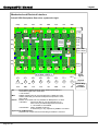
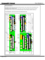
User Manual CompactPCI Backplanes 73972-101 Rev.000 CompactPCI Manual Overview What is The latest specification for PCI-based industrial computers is called CompactPCI. It is electrically, a superset of desktop PCI with a different physical form factor. CompactPCI utilizes the Eurocard form factor popularized by the VME bus. Defined for both 3U (100mm by 160 mm) and 6U (160mm by 233 mm) card sizes, CompactPCI has the following features: Standard Eurocard dimensions (compliant with IEEE 1101.1 mechanical standards) High density 2mm Pin-and-Socket connectors (IEC approved and Bellcore qualified) Vertical card orientation for effective cooling Easy card retention Excellent shock and vibration characteristics Metal front panel User I/O connections on front or rear of module Standard chassis available from many suppliers Uses standard PCI silicon, manufactured in large volumes Staged power pins for Hot Swap capability Eight slots in basic configuration. Easily expanded with Bridge Chips What is PICMG PICMG (PCI Industrial Computer Manufacturers Group) is a consortium of over 600 companies who collaboratively develop open specifications for high performance telecommunications and industrial computing applications. The members of the consortium have a long history of developing leading edge products for these industries. CompactPCI Connector The CompactPCI connector is a shielded 2mm pitch, 5+2 row connector, compliant to IEC 61076-4-101. Main features of this connector are the pin stagging for hot swap and shielding for EMI/RFI protection. Page 1 of 25 CompactPCI Manual Schroff CPCI Backplanes Schroff CompactPCI Backplanes Schroff CompactPCI backplanes are fully compliant to the latest PICMG specifications. PICMG 2.0 R 3.0 PICMG 2.1 PICMG 2.6 PICMG 2.9 PICMG 2.10 cPCI Core Specification cPCI Hot Swap Specification Bridging Specification System Management Bus Specification Keying Specification Schroff CompactPCI backplanes are specially designed to achieve exellent power distribution, best signal integrity, virtually zero cross talk, and minimum clock skew. The SMD components used on Schroff CompactPCI backplanes lead to a much lower failure rate than conventional components. Schroff uses ceramic capacitors on the CompactPCI backplanes to gain a better noise reduction at frequencies above 10MHz. This feature reduces the radiated and conducted noise caused by the processor and PCI clock signals. In addition, ceramic capacitors have no limitation in useful lifetime, as compared to aluminium capacitors that dry out after 5 to 10 years, and are unaware of the hazardous fire risks known from tantalum electrolytics’. Schroff CompactPCI Backplane Features Isolated Assembling / Connection to ChassisGND Schroff cPCI backplanes have a specially designed pattern of mounting holes to assemble the backplane isolated or connected to ChassisGND. For isolation between BackplaneGND and ChassisGND M2.5 screws and isolating washers should be used in at least every second connector position. If noise reduction shall be achieved by connecting DigitalGND to ChassisGND conductive spring washers are recommended instead of isolating ones. VI/O Schroff CompactCPCI backplanes have a complete power plane for the VI/O voltage. The VI/O plane can be connected using a bridge on the power bugs to +3.3V or +5V. By default, Schroff CompactPCI backplanes have VI/O connected to +5V with blue coding keys on P1. VI/O can also be set to 3,3V with the conversion kit 21101-658 (including 8 yellow keys and a tool) and change of the VI/O bridge position on the rear side of the backplane. Schroff CompactPCI backplanes are, on request, also avaiable with VI/O set to 3,3V. Stiffener The Schroff 6U CompactPCI backplanes are equiped with Stiffeners to reduce bending of the backplane during insertion and extraction of the cPCI cards to a minimum. Page 2 of 25 CompactPCI Manual Schroff CPCI Backplanes Geographical Addressing (GA) Geographical addressing is set by default to start from number one from left (upper) position within the chassis. If more than one backplane shall be assembled, a change of geographical addresses can be made. Cut copper links in between SMD pads to open, apply a zero Ohm resistor to close. Package size shall be 0603. Position is labelled "nGA[x]" where "n" stands for slot# , and "x" for address#, see chapter „Mechanical and Electrical Interface”. Physical Slot Addresses Physical Slot# GA[4] (J2-A22) GA[3] (J2-B22) GA[2] (J2-C22) GA[1] (J2-D22) GA[0] (J2-E22) 0(1) GND GND GND GND GND 1 GND GND GND GND open 2 GND GND GND open GND 3 GND GND GND open open 4 GND GND open GND GND 5 GND GND open GND open 6 GND GND open open GND 7 GND GND open open open 8 GND open GND GND GND 9 GND open GND GND open 10 GND open GND open GND Physical Slot# GA[4] (J2-A22) GA[3] (J2-B22) GA[2] (J2-C22) GA[1] (J2-D22) GA[0] (J2-E22) 11 GND open GND open open 12 GND open open GND GND 13 GND open open GND open 14 GND open open open GND 15 GND open open open open 16 open GND GND GND GND 17 open GND GND GND open 18 open GND GND open GND 19 open GND GND open open 20 open GND open GND GND 21 open GND open GND open 66MHz Operation Schroff cPCI backplanes are designed in accordance with the requirements of cPCI Core Specification, Revision 3.0 (PICMG 2.0 R3.0). Up to 5 Slots 66MHz operation is possible, signal M66 is HIGH (open). Backplanes of higher slot count also fulfil the 66MHz operation requirements in terms of clock trace length and skew, but M66 is tied to GND to disable 66MHz operation by default. This link is made by a removable copper link. For test purposes, it can be opened and closed again by using a zero Ohm resistor of size 0603. For position of the link see chapter „Mechanical and Electrical Interface”. Hot Swap Schroff cPCI backplanes fulfill the requirements for Basic Hot Swap of the Hot Swap Specification PICMG 2.1 R2.0. The signal BD_SEL# is tied to GND by a removable copper link. It can be replaced by a resistor-capacitor combination, both of package size 0603. Position is labelled "nB" where "n" stands for slot# , see chapter „Mechanical and Electrical Interface”. The P1 connector on Schroff cPCI backplanes has pin stagging needed for hot swap capabilities. Termination Termination on backplanes according to PICMG 2.0 R 3.0 is recommended in one case only. If, on a 8 slot backplane, strong buffers are used and only the system and the first adjacent slot are occupied and all others are empty. Schroff has implemented a special connector on the 8 Slot cPCI backplanes, where a Termination Board can be assembled. For slot counts 4 to 7, this connector is used for assembling a cPCI Bridge, see chapter „Mechanical and Electrical Interface”. Schroff is offering a 64-bit Termination Board, order code 23006931. Page 3 of 25 CompactPCI Manual Connector Pinouts Connectors on Schroff CompactPCI Backplanes Pin Assignment CPCI Connectors Table 1: CompactPCI System Slot 64-Bit Connector Pin Assignment Pin Z A B C D E F 22 GND GA4 GA3 GA2 GA1 GA0 GND 21 GND CLK6 GND RSV RSV RSV GND 20 GND CLK5 GND 19 GND GND GND 18 GND BRSVP2A18 BRSVP2B18 BRSVP2C18 GND BRSVP2E18 GND 17 GND BRSVP2A17 GND PRST# REQ6# GNT6# GND 16 GND BRSVP2A16 BRSVP2B16 DEG# GND BRSVP2E16 GND 15 GND BRSVP2A15 GND FAL# REQ5# GNT5# GND 14 GND AD[35] AD[34] AD[33] GND AD[32] GND 13 GND AD[38] GND AD[37] AD[36] GND 12 GND AD[42] AD[41] 11 GND AD[45] GND 10 GND AD[49] AD[48] 9 GND AD[52] GND 8 GND AD[56] AD[55] 7 GND AD[59] GND 6 GND AD[63] AD[62] 5 GND C/BE[5]# GND (2) RSV GND SMB_SDA (11) (2) V(I/O) AD[40] (2) V(I/O) AD[47] (2) V(I/O) AD[54] (2) V(I/O) AD[61] (2) V(I/O) SMB_SCL RSV (11) SMB_ALERT# GND (11) GND GND AD[39] GND AD[44] AD[43] GND GND AD[46] GND AD[51] AD[50] GND GND AD[53] GND AD[58] AD[57] GND GND AD[60] GND C/BE[4]# PAR64 GND 4 GND V(I/O) BRSVP2B4 C/BE[7]# GND C/BE[6]# GND 3 (3) GND CLK4 GND GNT3# REQ4# GNT4# GND 2 (3) GND CLK2 CLK3 SYSEN# GNT2# REQ3# GND 1 (3) GND CLK1 GND REQ1# GNT1# REQ2# GND 25 GND 5V REQ64# 3.3V 5V GND 24 GND AD[1] 5V AD[0] ACK64# GND 23 GND 3.3V AD[4] AD[3] AD[2] GND 22 GND AD[7] GND 3.3V AD[6] AD[5] GND 21 GND 3.3V AD[9] AD[8] M66EN C/BE[0]# GND 20 GND AD[12] GND V(I/O) AD[11] AD[10] GND 19 GND 3.3V AD[15] AD[14] GND (4) AD[13] GND 18 GND SERR# GND 3.3V C/BE[1]# GND (4) GND PERR# GND STOP# LOCK# GND GND TRDY# GND (3) ENUM# (2),(4) V(I/O) 5V (4) (2) 17 GND 3.3V IPMB_SCL 16 GND DEVSEL# GND (PCIXCAP) 15 GND 3.3V FRAME# PAR IPMB_SDA (2) V(I/O) IRDY# 14 KEY AREA 13 KEY AREA 12 (4) KEY AREA 11 GND AD[18] AD[17] AD[16] 10 GND AD[21] GND 3.3V (4) GND C/BE[2]# GND AD[20] AD[19] GND (4) 9 GND C/BE[3]# GND AD[23] GND AD[22] GND 8 GND AD[26] GND V(I/O) AD[25] AD[24] GND 7 GND AD[30] AD[29] AD[28] GND (4) AD[27] GND 6 GND REQ0# GND CLK0 AD[31] GND GNT0# GND INTS GND INTD# GND 5 GND BRSVP1A5 4 GND IPMB_PWR 3 GND INTA# 2 GND BRSVP1A2 5V 1 GND 5V -12V Pin Z A B Page 4 of 25 3.3V BRSVP1B5 HEALTHY# INTB# (10) (2) (13) (4) (4) RST# GND (2),(4) V(I/O) INTC# 5V BRSVP1C2 (10) BRSVP1C1 (10) C INTP (4) RSV (10) (10) RSVI GND +12V 5V GND D E F CompactPCI Manual Connector Pinouts Table 2: CompactPCI Peripheral Slot 64-Bit Connector Pin Assignment (1)(10, 11) Pin Z A B C D E F 22 GND GA4 GA3 GA2 GA1 GA0 GND 21 GND RSV RSV RSV RSV RSV GND 20 GND RSV RSV RSV GND RSV GND 19 GND RSV RSV RSV RSV RSV GND 18 GND BRSVP2A18 BRSVP2B18 BRSVP2C18 GND BRSVP2E18 GND 17 GND BRSVP2A17 GND RSV RSV RSV GND 16 GND BRSVP2A16 BRSVP2B16 RSV GND BRSVP2E16 GND 15 GND BRSVP2A15 GND RSV RSV RSV GND 14 GND AD[35] AD[34] AD[33] GND AD[32] GND AD[37] AD[36] GND GND AD[39] GND AD[44] AD[43] GND GND AD[46] GND AD[51] AD[50] GND GND AD[53] GND AD[58] AD[57] GND GND AD[60] GND 13 GND AD[38] GND 12 GND AD[42] AD[41] 11 GND AD[45] GND 10 GND AD[49] AD[48] 9 GND AD[52] GND 8 GND AD[56] AD[55] 7 GND AD[59] GND 6 GND AD[63] AD[62] 5 GND C/BE[5]# 4 GND V(I/O) 3(3) GND 2(3) (2) V(I/O) AD[40] (2) V(I/O) AD[47] (2) V(I/O) AD[54] (2) V(I/O) AD[61] (2) C/BE[4]# PAR64 GND BRSVP2B4 GND C/BE[7]# GND C/BE[6]# GND RSV GND RSV RSV RSV GND GND RSV RSV RSV RSV GND 1(3) GND RSV GND RSV RSV RSV GND 25 GND 5V REQ64# ENUM# 3.3V 5V GND 24 GND AD[1] 5V AD[0] ACK64# GND 23 GND 3.3V AD[4] AD[3] AD[2] GND (4) (2) V(I/O) UNC (3) (2),(4) V(I/O) 5V 22 GND AD[7] GND 3.3V 21 GND 3.3V AD[9] AD[8] 20 GND AD[12] GND 19 GND 3.3V AD[15] 18 GND SERR# GND 3.3V 17 GND 3.3V IPMB_SCL IPMB_SDA 16 GND DEVSEL# GND (PCIXCAP) 15 GND 3.3V FRAME# AD[6] AD[5] GND M66EN C/BE[0]# GND V(I/O) AD[11] AD[10] GND AD[14] GND (4) AD[13] GND (2) C/BE[1]# GND GND PAR (4) PERR# GND STOP# LOCK# GND TRDY# GND C/BE[2]# GND AD[20] AD[19] GND GND (4) AD[22] GND V(I/O) AD[25] AD[24] GND AD[28] GND (4) AD[27] GND CLK AD[31] GND GNT# GND INTS GND INTD# GND (10) GND (2) V(I/O) IRDY# BD_SEL# 14 KEY AREA 13 KEY AREA 12 (6) KEY AREA 11 GND 10 GND AD[21] 9 GND C/BE[3]# 8 GND AD[26] GND 7 GND AD[30] AD[29] AD[18] AD[17] GND AD[23] (2) GND REQ# GND 5 GND BRSVP1A5 BRSVP1B5 4 GND IPMB_PWR 3 GND INTA# INTB# 3.3V (13) (4) (4) RST# GND (2),(4) V(I/O) INTC# 2 GND 5V BRSVP1C2 1 GND 5V -12V BRSVP1C1 (10 Pin Z A B C INTP 5V (10 BRSVP1A2 (10) GND 3.3V (6) IDSEL HEALTHY# (4) AD[16] 6 Page 5 of 25 (4) (4) RSV (10) RSV +12V 5V GND D E F CompactPCI Manual Connector Pinouts Table 3: CompactPCI System Slot 32-Bit (Rear Panel I/O) Connector Pin Assignment Pin Z A B C D E F 22 GND GA4 GA3 GA2 GA1 GA0 GND 21 GND CLK6 GND BP(I/O) BP(I/O) BP(I/O) GND 20 GND CLK5 GND BP(I/O) BP(I/O) BP(I/O) 19 GND GND GND SMB_SDA 18 GND BP(I/O) BP(I/O) BP(I/O) BP(I/O) 17 GND BP(I/O) BP(I/O) PRST# 16 GND BP(I/O) BP(I/O) DEG# 15 GND BP(I/O) BP(I/O) 14 GND BP(I/O) 13 GND 12 GND 11 (11) SMB_SCL (11) SMB_ALERT# GND (11) GND BP(I/O) GND REQ6# GNT6# GND GND BP(I/O) GND FAL# REQ5# GNT5# GND BP(I/O) BP(I/O) BP(I/O) BP(I/O) GND BP(I/O) BP(I/O) BP(I/O) BP(I/O) BP(I/O) GND BP(I/O) BP(I/O) BP(I/O) BP(I/O) BP(I/O) GND GND BP(I/O) BP(I/O) BP(I/O) BP(I/O) BP(I/O) GND 10 GND BP(I/O) BP(I/O) BP(I/O) BP(I/O) BP(I/O) GND 9 GND BP(I/O) BP(I/O) BP(I/O) BP(I/O) BP(I/O) GND 8 GND BP(I/O) BP(I/O) BP(I/O) BP(I/O) BP(I/O) GND 7 GND BP(I/O) BP(I/O) BP(I/O) BP(I/O) BP(I/O) GND 6 GND BP(I/O) BP(I/O) BP(I/O) BP(I/O) BP(I/O) GND 5 GND BP(I/O) BP(I/O) BP(I/O) BP(I/O) BP(I/O) GND 4 GND V(I/O) BP(I/O) BP(I/O) BP(I/O) BP(I/O) GND 3(3) GND CLK4 GND GNT3# REQ4# GNT4# GND 2(3) GND CLK2 CLK3 SYSEN# GNT2# REQ3# GND 1(3) GND CLK1 GND REQ1# GNT1# REQ2# GND 25 GND 5V REQ64# ENUM# 3.3V 5V GND 24 GND AD[1] 5V AD[0] ACK64# GND 23 GND 3.3V AD[4] AD[3] AD[2] GND (4) (3) (2),(4) V(I/O) 5V 22 GND AD[7] GND 3.3V 21 GND 3.3V AD[9] AD[8] 20 GND AD[12] GND 19 GND 3.3V AD[15] 18 GND SERR# GND 3.3V 17 GND 3.3V IPMBSCL IPMBSDA 16 GND DEVSEL# GND (PCIXCAP) 15 GND 3.3V FRAME# AD[6] AD[5] GND M66EN C/BE[0]# GND V(I/O) AD[11] AD[10] GND AD[14] GND (4) AD[13] GND (2) PAR (2) V(I/O) IRDY# 14 KEY AREA 13 KEY AREA 12 (4) C/BE[1]# GND GND (4) PERR# GND STOP# LOCK# GND GND TRDY# GND C/BE[2]# GND AD[20] AD[19] GND GND (4) AD[22] GND KEY AREA 11 GND 10 9 (4) AD[18] AD[17] AD[16] GND AD[21] GND 3.3V GND C/BE[3]# GND AD[23] 8 GND AD[26] GND V(I/O) AD[25] AD[24] GND 7 GND AD[30] AD[29] AD[28] GND (4) AD[27] GND (2) 6 GND REQ0# GND 5 GND BRSVP1A5 BRSVP1B5 4 GND IPMBPWR 3 GND INTA# HEALTHY# INTB# 3.3V (13) (4) CLK0 (4) RST# GND (2),(4) V(I/O) INTC# 2 GND 5V BRSVP1C2 1 GND 5V -12V BRSVP1C1 (10) Pin Z A B Page 6 of 25 C INTP 5V (10) BRSVP1A2 (10) GND (4) RSV (10) AD[31] GND GNT0# GND INTS GND INTD# GND (10) GND RSV +12V 5V GND D E F CompactPCI Manual Connector Pinouts Table 4: CompactPCI Peripheral Slot 32Bit (Rear-Panel I/O) Connector Pin Assignments (1)(3)(8,9) Pin Z A B C D E F 22 GND GA4 GA3 GA2 GA1 GA0 GND 21 GND BP(I/O) BP(I/O) BP(I/O) BP(I/O) BP(I/O) GND 20 GND BP(I/O) BP(I/O) BP(I/O) BP(I/O) BP(I/O) GND 19 GND BP(I/O) BP(I/O) BP(I/O) BP(I/O) BP(I/O) GND 18 GND BP(I/O) BP(I/O) BP(I/O) BP(I/O) BP(I/O) GND 17 GND BP(I/O) BP(I/O) BP(I/O) BP(I/O) BP(I/O) GND 16 GND BP(I/O) BP(I/O) BP(I/O) BP(I/O) BP(I/O) GND 15 GND BP(I/O) BP(I/O) BP(I/O) BP(I/O) BP(I/O) GND 14 GND BP(I/O) BP(I/O) BP(I/O) BP(I/O) BP(I/O) GND 13 GND BP(I/O) BP(I/O) BP(I/O) BP(I/O) BP(I/O) GND 12 GND BP(I/O) BP(I/O) BP(I/O) BP(I/O) BP(I/O) GND 11 GND BP(I/O) BP(I/O) BP(I/O) BP(I/O) BP(I/O) GND 10 GND BP(I/O) BP(I/O) BP(I/O) BP(I/O) BP(I/O) GND 9 GND BP(I/O) BP(I/O) BP(I/O) BP(I/O) BP(I/O) GND 8 GND BP(I/O) BP(I/O) BP(I/O) BP(I/O) BP(I/O) GND 7 GND BP(I/O) BP(I/O) BP(I/O) BP(I/O) BP(I/O) GND 6 GND BP(I/O) BP(I/O) BP(I/O) BP(I/O) BP(I/O) GND 5 GND BP(I/O) BP(I/O) BP(I/O) BP(I/O) BP(I/O) GND 4 GND BP(I/O) BP(I/O) BP(I/O) BP(I/O) BP(I/O) GND 3 GND BP(I/O) BP(I/O) BP(I/O) BP(I/O) BP(I/O) GND 2 GND BP(I/O) BP(I/O) BP(I/O) BP(I/O) BP(I/O) GND 1 GND BP(I/O) BP(I/O) BP(I/O) BP(I/O) BP(I/O) GND 25 GND 5V REQ64# ENUM# 3.3V 5V GND 24 GND AD[1] 5V AD[0] ACK64# GND 23 GND 3.3V AD[4] AD[3] AD[2] GND (4) (2),(4) V(I/O) 5V 22 GND AD[7] GND 3.3V 21 GND 3.3V AD[9] AD[8] 20 GND AD[12] GND 19 GND 3.3V AD[15] 18 GND SERR# GND 3.3V 17 GND 3.3V IPMB_SCL IPMB_SDA 16 GND DEVSEL# GND (PCIXCAP) 15 GND 3.3V FRAME# AD[6] AD[5] GND M66EN C/BE[0]# GND V(I/O) AD[11] AD[10] GND AD[14] GND (4) AD[13] GND (2) C/BE[1]# GND GND PAR (4) PERR# GND STOP# LOCK# GND TRDY# GND C/BE[2]# GND AD[20] AD[19] GND GND (4) AD[22] GND V(I/O) AD[25] AD[24] GND AD[28] GND (4) AD[27] GND CLK AD[31] GND GNT# GND INTS GND INTD# GND (10) GND (2) V(I/O) IRDY# BD_SEL# 14 KEY AREA 13 KEY AREA 12 (5) KEY AREA 11 GND 10 GND AD[21] 9 GND C/BE[3]# 8 GND AD[26] GND 7 GND AD[30] AD[29] AD[18] AD[17] GND AD[23] (2) GND REQ# GND 5 GND BRSVP1A5 BRSVP1B5 4 GND IPMB_PWR 3 GND INTA# INTB# 3.3V (13) (4) (4) RST# GND (2),(4) V(I/O) INTC# 2 GND 5V BRSVP1C2 1 GND 5V -12V BRSVP1C1 (10) Pin Z A B C INTP 5V (10) BRSVP1A2 (10) GND 3.3V (6) IDSEL HEALTHY# (4) AD[16] 6 Page 7 of 25 (4) (4) RSV (10) RSV +12V 5V GND D E F CompactPCI Manual Connector Pinouts Notes for CompactPCI Pin Assignment Tables 1 through 4 1. These diagrams define the pin assignments from the front of the system chassis. 2. The V(I/O) signals are either 5 V or 3.3 V, depending on the system implementation. 3. Connector P2 pin C2 is grounded at the System Slot only. Peripheral slots leave C2 unconnected (UNC). Boards that use this signal (e.g., CPU boards that may be used in the System Slot or Peripheral Slot) shall provide a local pull-up to V(I/O). Boards designed for System Slot only use should tie this pin directly to the ground plane. 4. The following signals are long (level 3) pins in P1 for early power to hot swap boards: D3, D5, D7, D9, D11, D17, D19, D23, C4, C6, C22, C24. 5. Connector P1 pin D15 (BD_SEL#) is defined as a short length pin and is used for the final connection sequence by hot swap boards. Connector P1 pin B9 (IDSEL) is defined as a short length pin. Refer to PICMG 2.1, CompactPCI Hot Swap Specification for details. 6. These signals are defined as bussed reserve (BRSVPxxx) signals. They were defined as PCI cache signals SDONE# and SBO# (Defined in the PCI 2.1 Specification) in earlier revisions of this specification. 7. CompactPCI connector pin numbering is intentionally different from the connector manufacturer’s pin numbering. This was done to allow the connectors to start at the bottom of the board and “grow” upward from J1/P1 through J5/P5. 8. BP(I/O) signals are defined as “long” tail connectors with 16.0 mm tails. Refer to IEEE 1101.11 for details. All other signals in P1 and P2 are defined to be “short” tail connectors with 4.5 mm tails. 9. BRSVPxxx signals accommodate PCI reserved signals. Bus segments shall bus these signals between connectors. 10. Usage of JTAG signals is discouraged. These signal definitions will be redefined in a future revision of the CompactPCI specification. Backplanes shall bus pins A2 (TCK), C2 (TMS) and C1 (TRST#) to all CompactPCI Slots. Pins D2 (TDO) and E2 (TDI) should be non-bussed. 11. System slot connector P2, pins C19 (SMBB_SDA), D19 (SMBB_SCL) and E19 (SMB_RSV) have been defined by the System Management Subcommittee as the appropriate rear-panel I/O pins to be used for a 2 secondary I C bus local to the system board. Refer to the PICMG 2.9 System Management Specification for further information. 12. Signals IDSEL and BD_SEL# are connected to GND on the System Slot. The Dual Host Subcommittee may further define their use on the system slot. 13. P1 pin B4 is reserved for HEALTHY#. Backplane must leave this pin open and include a bypass capacitor, refer to section 3.2.10 and the CompactPCI Hot Swap Specification, PICMG 2.1 for details. Utility-, Sense-, IPMB- Connectors A 6 5 4 3 2 1 B 6 5 4 3 2 1 A nc nc +12V GND FAL# nc Pin Signal 1 2 3 4 5 SCL GND SDA Vsm nc B nc. -12V 3,3V +5V DEG# PRST# Utility / SENSE Connector Pinout Sense: Voltage rails +5V; 3,3V; +12V and GND of these connectors used for sense purposes. They should be connected to the backplane. Some Power Supplies need at least a connection to GND, otherwise the outputs overrun. FAL#: Signal driven by intelligent PSU's, at least one output has failed (is out of range). DEG#: Signal driven by intelligent PSU's, PSU indicates that the supply is beginning to derate its power output. Cable assy Page 8 of 25 23204-115 (350mm) 23204-116 (600mm) IPMB Connector (Top view on connector) Vsm (Power) can be connected to +5V by using zero Ohm resistor of size 0603 (R100). Cable assy 23204-113 (750mm) CompactPCI Manual Layout Mechanical and Electrical Interface Schroff CPCI Backplane, Rear view, system slot right Utility 3,3V VI/O +5V GND 3,3V +5V GND Power Bugs IPMB0 IPMB1 VI/O Bridge +5V nGA[0] nGA[1] nGA[2] nGA[3] nGA[4] R100 VI/O (P5) (P4) (P3) 64Bit P2 3,3V 3U / 6U: M66 Bridge connector to secondary BP 128,7 / 262,05 32Bit +12V nB nB P1 -12V # of slots x 20,32 -1 1P1 2P1 3P1 4P1 5P1 6P1 7P1 8P1 8 7 6 5 4 3 2 1 3,3V +12V +5V GND -12V 3,3V +5V GND 3,3V Board Select resistor/capacitor pads; default grounded by a removable copper link in outer layer; n: slot number; 66MHz enabling line can be grounded using a 0603 zero Ohm M66: resistor; default is grounded for backplanes comprised of more than 5 slots Faston Blades on left hand side only available on Backplanes < 4 Slots: 3 Slot BPs: VI/O Power Bug on Top is replaced by 3,3V VI/O is set by a cable bridge between Fastons +/- 12V Fastons not available 1&2 Slot BPs: Faston available as shown no Power Bug on Top, replaced by IPMB0/1 connector System Slot left Backplanes placement of components and Power Bug annotation is mirrored nB: Page 9 of 25 +5V Slot #: logical physical Power Bug Voltage Annotation CompactPCI Manual 1 Slot CPCI Backplane Schroff 1-Slot 3U cPCI Backplane, 23006-811 Purpose The 1 Slot Backplane provides power to a cPCI CPU Board. There are no bussed signals, connector P2 is compatible to the 32Bit System Slot pinout and comprises Rear I/O functionality Mechanical and Electrical Interface Rear view Pinout VI/O connector VI/O GND +5V 3,3V P2 +5V 3U: 128,7 3,3V GND Pinout 12V connector P1 +12V -12V GND GND 19,32 1P1 Slot #: logical 1 physical VI/O connector 12V connector Power connectors top view on connector top view on connector +5V, 3,3V & GND 6,3mm Faston blades, VI/O GND +12V -12V +5V 3,3V GND GND b/p connector: Molex # 43045-0418 free connector: Molex # 43025-0400 crimp contact: Molex # 43030-0007 (AWG 20-24, tin plated, Bag) Page 10 of 25 b/p connector: Molex # 43045-0418 free connector: Molex # 43025-0400 crimp contact: Molex # 43030-0007 (AWG 20-24, tin plated, Bag) fit with every 6,3mm Faston, available from different manufacturers CompactPCI Manual Special CPCI Backplanes Schroff CompactPCI Backplanes for Special Applications I/O Board 1 Slot backplane 3U for upper position in a 6U environment. Backplane includes connectors P4 and P5 with long pins and shrouds. Used if 3U backplane should be installed with 6U Boards. The I/O Board connects P4 and P5 from front to rear I/O board. Order Code 23090-719 cPCI Backplane for 1U Vertical System (ATX) Schroff has designed a special cPCI backplane that fit into a 1U system with vertical card cage. This backplane combines the 6U cPCI backplane, 64-bit cPCI bus, with 2 slot and Molex connectors for power supply (ATX) and fans. FAN (front) Utility Features Fan Connector 1 1 2 3 4 5 6 +5V +12V +12V GND GND GND System slot left Placement of power connectors underneath the P1 connector row to reduce voltage drop to a minimum. Connectors for IPMB on board. Power bugs to connect VI/O to +5V or +3,3V IPMB0 IPMB1 Order Code 23006-793, 2 Slot, 2 Minifit connectors. X522 Connector 1 1 2 3 4 5 6 7 8 9 10 Page 11 of 25 +5V GND +3.3V GND +12V +5V GND +3.3V GND -12V +3.3V V I/O X522 (front) +5V CompactPCI Manual Special CPCI Backplanes cPCI Backplanes with P47 Connectors for 1 to 4U Vertical Systems Schroff has designed special cPCI backplanes that fit into 1 to 4U systems with vertical card cage. These backplanes combine the 6U cPCI backplane, 64-bit cPCI bus, 2 to 8 slots and the P47 connectors for power supplies. Backplanes with 2 and 8 Slots are stock items, 4 and 6 slot on request. Features System slot left Placement of power connectors underneath the P1 connector row to reduce voltage drop to a minimum. Starting from 4 Slot backplane, two P47 connectors assembled. Redundant and parallel operation of power supplies possible. Connectors for IPMB, Utility, Disk- Drive, PSU-Status, fantray, temperature sensors, and Inhibit on board. Power bugs for every voltage present as optional power input or output (max. 30A per voltage). Order Code 23006-794 23006-795 23006-796 23006-797 Status Fan 1 2 3 4 5 6 7 8 9 10 Sig1 +12V +12V GND GND +5V fanfail tempfail GND Signal 1 Signal 2 Page 12 of 25 nc GND Signal 1 Sig2 1 2 3 nc GND Signal 2 X155 INH# 1 2 1 2 3 INH# GND 1 2 +5V GND 3 4 GND +12V 2 Slot, 1 P47 connector 4 Slot, 2 P47 connectors 6 Slot, 2 P47 connectors, 3 connectors on request 8 Slot, 2 P47 connectors, 3 or 4 connectors on request CompactPCI Manual Special CPCI Backplanes 161,54 39,88 9,91 FAN 1 Utility IPMB0 IPMB1 1 X130 X140 X120 Status 6 +5V 395,48 X110 12 V I/O 1 INH# +3,3V SIG1 1 SIG2 1 97,79 GND GND X155 -12V +12V Page 13 of 25 CompactPCI Manual Power Concept Modular Power Concept Power Bugs Schroff cPCI backplanes are populated with specially designed power bugs. The power cables can be connected to the power bugs with cable lugs fastened with M4 screws. Each power bug can handle 30 Amps. Schroff has designed various cables and power boards to be assigned to these power bugs. They provide interfaces for many different PSU types. ATX Cable Assembled on the power bugs of the CompactPCI backplanes, the ATX cable provides the mating connector for an ATX power supply. Order Code 23204-121 ATX(M) to Ring Term 250mm ATX Piggy Back The Power Piggyback board can be used if ATX PSU's shall be connected to a Backplane. In this case the signal "INH#" at connector X15 shall be jumpered to GND that the ATX-PSU power up. Connector X15 is jumpered for ATX PSU's by default. If other PSU's like CPCI PSU's (acc. to PICMG 2.11) shall be used, than the jumper should be removed. Oder Code 23098-100 Page 14 of 25 ATX Connector Pinout +3.3V -12V GND INH# GND GND GND nc +5V +5V 11 1 12 2 13 3 14 4 15 5 16 6 17 7 18 8 19 9 20 11 +3.3V +3.3V GND +5V GND +5V GND FAL# nc +12V pinout: top view on connector free connector: Molex # 39-01-2205 crimp terminal: Molex # 39-00-0039 (AWG 18-24, Bag) CPCI Signal INH# uses a pin defined within the ATX spec as PS-ON; both (INH#, PS-ON) used to drive the PSU ON/OFF; Logic Level is reversed; to drive PSU on, drive INH#: HIGH (PCMG 2.11 PSU's) PS-ON: LOW (ATX PSU's) Disk Drive Power Connector (X5, X6) +12V GND GND +5V board connector: Molex # 15-24-4049 free connector: Molex # 15-24-3053 (IDC, AWG 16) Connector X15 1: INH# 2: GND 3: FAL# CompactPCI Manual Power Backplanes Power Backplane with P47 Connector According to PICMG 2.9 PICMG 2.11 System Management Spezifikation Compact PCI Power Interface Spezifikation Power backplane to support pluggable PSUs with P47 connector. Power backplane has 8/16HP width and can be assembled anywhere in the system. The power backplane can easily be connected electrically to the cPCI backplane by using the cables supplied with the power board. Power input to the power backplane with crimp contacts plugged directly into the P47 connectors. Parallel operation of 2 PSUs possible by connecting the current share bus on both power boards. 3U power backplane 8HP assembled with one P47 connector, 3U backplane 16HP with 2 P47, the 6U power backplane with 1 or 2 P47 connectors. Order Code 23098-105 23098-115 23098-116 23098-117 1 PSU Slot (8HP), 3U Board, connector for 1 PSU 2 PSU Slots (16HP), 3U Board, connectors for 2 PSU´s 1 PSU Slot, 6U Board (8HP), 1 PSU connector for one 6U PSU 1 PSU Slot, 6U Board (8HP), 2 PSU connectors for two 3U PSU's Sense Option Sensing can be accomplished by three different options: using the Utility/Sense connector; all voltages are sensed (X7/8) using the Inhibit/Sense connector, the main voltages (+5V, 3,3V GND) can be connected to backplanes not assembled with the Utility connector by easy wiring (X25) only GND-Sense is connected to GND at the Power Board for minimum requirements of some PSU'S (Jumper X24) GND-Sense Jumper (X24) Some PSUs may require at least that sense return (GND Sense) is connected to GND to avoid output voltages out of range. For easy implementation, X24 can be shorted to connect GND Sense to GND of the power board A 6 5 4 3 2 1 Utility / SENSE Connector Pinout (X7, X8) B 6 5 4 3 2 1 A nc nc +12V GND DEG# nc B INH# -12V 3,3V +5V FAL# nc Sense pins referred to voltages +5V; 3,3V; +12V and GND of these connector are used for sense purposes. They should be connected to the backplane. The -12V pin is connected to the -12V power rail. Some power supplies need at least a connection between GND_Sense and GND, otherwise the outputs overrun. FAL#: Signal driven by intelligent PSUs, at least one output has failed (is out of range) DEG#: Signal driven by intelligent PSUs, PSU indicates that the supply is beginning to derate its power output INH#: Signal to turn the PSU outputs "on/off"; "open" or "HIGH": "on" / "LOW": "off" cable assy 23204-115 (350mm) cable assy 23204-116 (600mm) Page 15 of 25 CompactPCI Manual Power Backplanes Pin Assignment Positronic P47 (X1) Pin Assignment X9 1. Part type: header with or w/o housing and latches, grid: 100mil recommendation for mating connector: any IDC connector for ribbon cable of a pitch of 50 mil (acc. to DIN 41651) 2. FAL#_n, DEG#_n: n is the number of an individual PSU 3. To set the PSU signal FAL# or respectively DEG# to an individual line use jumper according the schematic given in Figure 3. Setting individual FAL# & DEG# Signal using Jumper array X14 - X18 for FAL# using Jumper array X19 – X23 for DEG# Jumper to set individual PSU 1 2 3 4 5 6 7 8 9 10 11 12 13 14 FAL#_1 FAL#_2 FAL#_3 FAL#_4 DEG#_1 DEG#_2 DEG#_3 DEG#_4 +3.3V share +5V share +12V share GND nc nc FAL# / DEG# to FAL#_1 / DEG#_1 X14 - X18 and X19 - X23 FAL# / DEG# to FAL#_2 / DEG#_2 FAL# / DEG# to FAL#_3 / DEG#_3 FAL# / DEG# to FAL#_4 / DEG#_4 FAL# / DEG# to Utility connector X7, X8 FAL# or DEG# from PSU ATX Power Connector (X3, X4) 3,3V 11 1 3,3V - 12V 12 2 3,3V pinout: top view on connector GND 13 3 GND INH# 14 4 +5V GND 15 5 GND free connector: Molex # 39-01-2205 crimp terminal: Molex # 39-00-0039 (AWG 18-24, Bag) GND 16 6 +5V GND 17 7 GND nc 18 8 FAL# +5V 19 9 nc +5V 20 10 +12V CPCI Signal INH# uses a pin defined within the ATX spec as PS-ON; both (INH#, PS-ON) used to drive the PSU ON/OFF; Logic Level is reversed; to drive PSU on, drive INH#: HIGH (PCMG 2.11 PSU's) PS-ON: LOW (ATX PSU's) Disk Drive Power Connector (X5, X6) GND +5V board connector: free connector: (IDC, AWG 16) Page 16 of 25 Molex # 15-24-4049 Molex # 15-24-3053 Description V1 V1 V1 V1 RTN RTN RTN RTN RTN RTN RTN RTN V2 V2 V2 V2 V2 V2 RTN V3 V4 RTN RESERVED RTN V4 GA0 RESERVED EN# GA1 V1ADJ V1 SENSE GA2 V2ADJ V2 SENSE S RTN V1 SHARE V3 SENSE IPMB_SCL DEG# INH# IPMB_SDA V2 SHARE FAL# IPMB_PWR V3 SHARE CGND 46 ACN/+DC IN 47 ACL/-DC V1 Output (+5V) V1 Output (+5V) V1 Output (+5V) V1 Output (+5V) V1 and V2 Return (GND) V1 and V2 Return (GND) V1 and V2 Return (GND) V1 and V2 Return (GND) V1 and V2 Return (GND) V1 and V2 Return (GND) V1 and V2 Return (GND) V1 and V2 Return (GND) V2 Output (3,3V) V2 Output (3,3V) V2 Output (3,3V) V2 Output (3,3V) V2 Output (3,3V) V2 Output (3,3V) V3 Return (GND) V3 Output (+12V) V4 Output (-12V) Signal Return (GND) Reserved V4 Return (GND) Geographic Address Bit 0 Reserved Enable (set to GND) Geographic Address Bit 1 V1 Adjust V1 Remote Sense Geographic Address Bit 2 V2 Adjust V2 Remote Sense Sense Return V1 Current Share V3 Remote Sense System Management Bus Degrade Signal Inhibit System Management Bus V2 Current Share Fail Signal System Management Bus V3 Current Share Chassis Ground (safety ground) AC Input – Neutral; +DC Input IN AC Input – Line; =-DC Input Remote Connector (X25) top view on connector top view on connector Pin GND Signal Name 1 2 3 4 5 5 7 8 9 10 11 12 13 14 15 16 17 18 19 20 21 22 23 24 25 26 27 28 29 30 31 32 33 34 35 36 37 38 39 40 41 42 43 44 45 IPMB Connector (X2) top view on connector +12V Pin# 1 2 3 4 5 Signal SCL GND SDA Vsm nc cable 750mm: 23204 - 113 free connector: Molex # 51021-0500 crimp contact: Molex # 50079-8100 Pin 5 4 3 2 1 Signal INH# GND +5V Sense 3,3V Sense Sense Return (GND) cable 750mm: 23204 - 114 free connector: Tyco# 643814-5 CompactPCI Manual Power Backplanes Start-up of the Board The cable tie of the power mains has to be opened and the crimp contacts have to be pushed into the dedicated connector chambers of X1; Corresponding cable colours: brown: L (line); blue: N (neutral); green/yellow: PE (protective earth). Cable length: 500mm, other end can be fitted with Faston crimp contacts (included in delivery). Power Backplanes, view from rear, X1 is assembled from front 23098 – 116/117 23098 – 105 X14 ... X18 DEG# X19 ... X23 X8 FAL# X2 DEG# X14 ... X18 X13 L N PE X4 X9 L N PE X19 ... X23 IPMB X8 X2 IPMB X7 X7 X24 GA2 GA1 GA0 X24 GA2 GA1 GA0 X6 X6 122,5 128,7 horizontal Dimensions: vertacal Dimensions: X9 X3 X5 X5 X1 the same for Backplanes of same width the same for 3U Backplanes X25 FAL# X1 262,05 23098 - 115 255,85 FAL# X9 X25 FAL# X114 ... X118 DEG# X119 ... X123 X114/X14 ... X118/X18 L N PE X25 GND L N PE DEG# X119/X19 ... X123/X23 -12V X8 L N PE +12V X7 X104 GA2 GA1 GA0 X103 X101 23,65 X24 GA2 GA1 GA0 3,3V 2GA2 2GA1 2GA0 +12V GND GND +5V X101 X2 X6 X1 X5 3,14 10,16 20,32 ≤ 39,64 Page 17 of 25 40,64 ≤ 80,28 14,05 CompactPCI Manual Order Code Available Backplanes and Accessories CompactPCI Backplanes 3U, 32-bit, System Slot left Article Number Slot Count Rear I/O V I/O Bus frequency 23006-811 1 yes +5V 33 / 66 MHz CompactPCI Backplanes 3U, 64-bit, System Slot left Article Number Slot Count Rear I/O V I/O Bus frequency 23006-811 1 yes +5V 33 / 66 MHz 23006-733 3 no +5V 33 / 66 MHz 23006-734 4 no +5V 33 / 66 MHz 23006-736 6 no +5V 33 MHz 23006-738 8 no +5V 33MHz CompactPCI Backplanes 6U, 64-bit, System Slot left Article Number Slot Count Rear I/O V I/O Bus frequency 23006-765 5 yes +5V 33 / 66 MHz 23006-768 8 yes +5V 33 MHz CompactPCI Backplanes 3U, 32-bit, System Slot right Article Number Slot Count Rear I/O V I/O Bus frequency 23006-811 1 yes +5V 33 / 66 MHz 23006-812 2 yes +5V 33 / 66 MHz 23006-813 3 yes +5V 33 / 66 MHz 23006-814 4 yes +5V 33 / 66 MHZ 23006-815 5 yes +5V 33 / 66 MHz 23006-816 6 yes +5V 33 MHz 23006-817 7 yes +5V 33 MHz 23006-818 8 yes +5V 33 MHz CompactPCI Backplanes 3U, 32-bit, System Slot right, Secondary Article Number Slot Count Rear I/O V I/O Bus frequency 23006-824 4 yes +5V 33 / 66 MHz 23006-827 7 yes +5V 33 MHz CompactPCI Backplanes 3U, 64-bit, System Slot right Article Number Slot Count Rear I/O V I/O Bus frequency 23006-811 1 yes +5V 33 / 66 MHz 23006-833 3 no +5V 33 / 66 MHz 23006-834 4 no +5V 33 / 66 MHz 23006-835 5 no +5V 33 / 66 MHz 23006-836 6 no +5V 33 MHz 23006-837 7 no +5V 33 MHz 23006-838 8 no +5V 33MHz Page 18 of 25 CompactPCI Manual Order Code CompactPCI Backplanes 3U, 64-bit, System Slot right, Secondary Article Number Slot Count Rear I/O V I/O Bus frequency 23006-854 4 no +5V 33 / 66 MHz 23006-857 7 no +5V 33 MHz CompactPCI Backplanes 6U, 64-bit, System Slot right Article Number Slot Count Rear I/O V I/O Bus frequency 23006-862 2 Yes +5V 33 / 66 MHz 23006-863 3 Yes +5V 33 / 66 MHz 23006-864 4 Yes +5V 33 / 66 MHz 23006-865 5 Yes +5V 33 / 66 MHz 23006-866 6 Yes +5V 33 MHz 23006-867 7 Yes +5V 33 MHz 23006-868 8 Yes +5V 33 MHz CompactPCI Backplanes 6U, 64-bit, System Slot right, Secondary Article Number Slot Count Rear I/O V I/O Bus frequency 23006-884 4 Yes +5V 33 / 66 MHz 23006-887 7 Yes +5V 33 MHz CompactPCI Backplanes „Special“ 6U, 64-bit, System Slot left Article Number Slot Count Rear I/O V I/O Bus frequency Power input 2 Yes +5V 33 / 66 MHz 1 x ATX 23006-792 23006-794 2 Yes +5V 33 / 66 MHz 1 x P47 23006-795 (3) 4 Yes +5V 33 / 66 MHz 2 x P47 23006-796 (3) 6 Yes +5V 33 MHz 2 x P47 (1) 8 Yes +5V 33 MHz 2 x P47 (2) 23006-797 (1): 3 P47 connectors on request; (2) 3 or 4 P47 connectors on request; (3) Backplanes available on request CompactPCI Bridges Article Number Page 19 of 25 Bus width / Orientation Bus frequency Description 23006-920 32-bit / right to left 33 / 66 MHz Low profile 23006-922 64-bit / right to left 33 / 66 MHz Low profile CompactPCI Manual Power Cable, Power Piggy, Power Backplanes Article Number Description 23204-121 Cable ATX(M) to Ring Terminals, 250mm length 23098-100 ATX Power Piggy 23098-105 Power Backplane 3U 8HP with 1 P47 connector 23098-115 Power Backplane 3U 16HP with 2 P47 connectors 23098-116 Power Backplane 6U 8HP with 1 P47 connector, upper position 23098-117 Power Backplane 6U 8HP with 2 P47 connectors, upper and lower position Accessories Article Number Page 20 of 25 Description 23204-110 Cable P47 Input Mains, 500mm length 23204-112 Cable ATX (F) to ring terminals, 250mm length 23204-113 Cable IPMB, 750mm length 23204-114 Cable Sense-Remote, 5-Way, 750mm length 23204-115 Cable Utility-Sense, 12-Way, 350mm length 23204-116 Cable Utility-Sense, 12-Way, 600mm length 23204-117 Cable Current Share, 14-Way, 100mm length 23204-134 Cable Remote AMP-MTA, 3-Way, 800mm length 21101-658 CPCI Conversion Kit, 8 yellow Coding keys plus tool, to set VI/O to 3,3V Order Code CompactPCI Manual Bridge Applications CompactPCI Bridge CompactPCI has been designed to accommodate up to 8 modules on a bus segment. Installing a bridge module on a bus segment consumes one of the loads on the segment but creates a new bus segment with up to 7 additional modules. The bridge module handles all communication between the bus segments. With the rear palette bridges from Schroff no valuable front slot is wasted. Due to the very low height of 10mm, even no rear I/O slot is wasted. Schroff offers a 32-bit and a 64-bit rear palette bridge, both for system slot right backplanes. Both are based on the Intel 21154 PCI-to-PCI bridge Chip. The maximum power consumption of this bridge module is 0.75W at +5V and 2.2 W at +3.3V. GND and the power supplies (+5V, +3.3V, +/-12V) are connected from the primary PCI bus to the secondary PCI bus. V(I/O) may be +3.3V or +5V on either side of the bridge. The bridge will automatically detect the bus voltage and adjust its I/O levels accordingly. Power Supply of Backplanes: Both backplanes connected by the bridge are to be powered individually. The bridge is not to be used for bridging power. The bridge does not isolate the power rails of both backplanes. GND is connected by a sufficient number of pins in the connector to ensure signal integrity and a common GND potential on both backplanes. CPCI Rear Brick Bridge 23006 – 922 63Bit PCI-to-PCI Bridge ≈ 100 64Bit, right-to-left HB2 304-pin BGA VI/O There is no need to choose the VI/O voltage for the bridge. The bridge automatically takes the VI/O voltage of the primary and secondary side. Both backplanes can be set to different VI/O voltages, e.g. +5V on the primary side and 3,3V on the secondary side. M66MHz Operation The bridge chips are capable of operating at 66MHz. The Bridges can operate with 33 MHz or 66MHz on primary and secondary side. It´s also possible to have the primary side operate at 66 MHz and the secondary at 33 MHz. ≤ 50 <10 part#: 23006 - 922 CPCI Rear Brick Bridge ≈ 60 32Bit, right-to-left 21150 256-pin BGA 23006-920 32-Bit Bridge right-to-left ≤ 50 <10 part#: 23006 - 920 Page 21 of 25 Mechanical Mounting Both backplanes should only be attached to the horizontal rails, but not fixed. The mounting screws of the backplane are not to be tightened until the bridge is plugged and fully seated! CompactPCI Manual Bridge Applications Block Wiring Diagram Primary CPCI Backplane Secondary CPCI Backplane PCI Bus 32 / 64Bit PCI Bus 32 / 64Bit (AD[nn]) Arbitration (1 Pair) PCI to PCI Bridge (REQn# /GNTn#) (AD[nn]) Arbitration (7 Pairs) (REQn# /GNTn#) PCI Clock (1x) (CLKn) CPCI Signals C/BE[n]; DEVSEL; FRAME; IDSEL; IRDY; LOCK; M66EN; PAR; REQ64, ACK64 RST; STOP; TRDY Interrupts (X= A...D) (INTX) Bussed Reserved Signals BRSVP1A5, BRSVP1B5 IPMB 32Bit Intel 21150; PCI Clock (7x) 64Bit: Hint 123 CPCI Signals (compatible to Intel 21154) 7407 0 Ohm 0 Ohm (SDA, SCL, PWR) legacy Interrupts 0 Ohm (INTS, INTP) JTAG Signals (TRST, TCK, TMS, TDO, TDI) 0 Ohm (CLKn) C/BE[n]; DEVSEL; FRAME; IDSEL; IRDY; LOCK; M66EN; PAR; REQ64, ACK64 RST; STOP; TRDY Interrupts (X= A...D) (INTX) Bussed Reserved Signals BRSVP1A5, BRSVP1B5 IPMB (SDA, SCL, PWR) legacy Interrupts (INTS, INTP) JTAG Signals (TRST, TCK, TMS, TDO, TDI) zero Ohm bridges assembled by default and can be removed/omitted optionally Possible Bridge Configurations 3U, 32-bit, Systemslot right Number of Slots 8 9 10 11 11 12 13 14 15 16 17 18 18 19 20 21 Configuration 4 + 4 Slot 5 + 4 Slot 6 + 4 Slot 7 + 4 Slot 4 + 7 Slot 5 + 7 Slot 6 + 7 Slot 7 + 7 Slot 4 + 7 + 4 Slot 5 + 7 + 4 Slot 6 + 7 + 4 Slot 7 + 7 + 4 Slot 4 + 7 + 7 Slot 5 + 7 + 7 Slot 6 + 7 + 7 Slot 7 + 7 + 7 Slot Bus frequency 33 / 66 MHz or mixed 33 / 66 MHz or mixed 33 MHz 33 MHz 33 MHz or mixed 33 MHz or mixed 33 MHz 33 MHz 33 MHz or mixed 33 MHz or mixed 33 MHz 33 MHz 33 MHz or mixed 33 MHz or mixed 33 MHz 33 MHz Articles needed 23006-814 + 23006-824 + 23006-920 23006-815 + 23006-824 + 23006-920 23006-816 + 23006-824 + 23006-920 23006-817 + 23006-824 + 23006-920 23006-814 + 23006-827 + 23006-920 23006-815 + 23006-827 + 23006-920 23006-816 + 23006-827 + 23006-920 23006-817 + 23006-827 + 23006-920 (1) 23006-814 + 23006-827 + 23006-824 + 2x 23006-920 (1) 23006-815 + 23006-827 + 23006-824 + 2x 23006-920 (1) 23006-816 + 23006-827 + 23006-824 + 2x 23006-920 (1) 23006-817 + 23006-827 + 23006-824 + 2x 23006-920 (1) 23006-814 + 2x 23006-827 + 2x 23006-920 (1) 23006-815 + 2x 23006-827 + 2x 23006-920 (1) 23006-816 + 2x 23006-827 + 2x 23006-920 (1) 23006-817 + 2x 23006-827 + 2x 23006-920 (1) If the backplane is used as tertiary backplane, the geographical address has to be changed. Please refer to chapter „Schroff CPCI Backplanes“, „Geographical addressing“. Page 22 of 25 CompactPCI Manual Bridge Applications 3U, 64-bit, Systemslot right Number of Slots Configuration Bus frequency Articles needed 8 9 10 11 11 12 4 + 4 Slot 5 + 4 Slot 6 + 4 Slot 7 + 4 Slot 4 + 7 Slot 5 + 7 Slot 33 / 66 MHz or mixed 33 / 66 MHz or mixed 33 MHz 33 MHz 33 MHz or mixed 33 MHz or mixed 23006-834 + 23006-854 + 23006-922 23006-835 + 23006-854 + 23006-922 23006-836 + 23006-854 + 23006-922 23006-837 + 23006-854 + 23006-922 23006-834 + 23006-857 + 23006-922 23006-835 + 23006-857 + 23006-922 12 13 13 14 4 + 4 + 4 Slot 6 + 7 Slot 5 + 4 + 4 Slot 7 + 7 Slot 33 / 66 MHz or mixed 33 MHz 33 / 66 MHz or mixed 33 MHz 23006-834 + 2x 23006-854 + 2x 23006-922 23006-836 + 23006-857 + 23006-922 (1) 23006-835 + 2x 23006-854 + 2x 23006-922 23006-837 + 23006-857 + 23006-922 15 15 16 16 17 18 7 + 4 + 4 Slot 4 + 4 + 7 Slot 5 + 7 + 4 Slot 5 + 4 + 7 Slot 6 + 7 + 4 Slot 7 + 7 + 4 Slot 33 MHz 33 MHz or mixed 33 MHz or mixed 33 MHz or mixed 33 MHz 33 MHz 23006-837 + 2x 23006-854 + 2x 23006-922 (1) 23006-834 + 23006-854 + 23006-857 + 2x 23006-922 (1) 23006-835 + 23006-857 + 23006-854 + 2x 23006-922 (1) 23006-835 + 23006-854 + 23006-857 + 2x 23006-922 (1) 23006-836 + 23006-857 + 23006-854 + 2x 23006-922 (1) 23006-837 + 23006-857 + 23006-854 + 2x 23006-922 18 19 20 21 4 + 7 + 7 Slot 5 + 7 + 7 Slot 6 + 7 + 7 Slot 7 + 7 + 7 Slot 33 MHz or mixed 33 MHz or mixed 33 MHz 33 MHz 23006-834 + 2x 23006-857 + 2x 23006-922 (1) 23006-835 + 2x 23006-857 + 2x 23006-922 (1) 23006-836 + 2x 23006-857 + 2x 23006-922 (1) 23006-837 + 2x 23006-857 + 2x 23006-922 (1) (1) (1) (1) If the backplane is used as tertiary backplane, the geographical address has to be changed. Please refer to chapter „Schroff CPCI Backplanes“, „Geographical addressing“. 6U, 64-bit, Systemslot right Number of Slots 8 9 10 11 11 Configuration 4 + 4 Slot 5 + 4 Slot 6 + 4 Slot 7 + 4 Slot 4 + 7 Slot Bus frequency 33 / 66 MHz or mixed 33 / 66 MHz or mixed 33 MHz 33 MHz 33 MHz or mixed Articles needed 23006-864 + 23006-884 + 23006-922 23006-865 + 23006-884 + 23006-922 23006-866 + 23006-884 + 23006-922 23006-867 + 23006-884 + 23006-922 23006-864 + 23006-887 + 23006-922 12 13 14 5 + 7 Slot 6 + 7 Slot 7 + 7 Slot 33 MHz or mixed 33 MHz 33 MHz 23006-865 + 23006-887 + 23006-922 23006-866 + 23006-887 + 23006-922 23006-867 + 23006-887 + 23006-922 16 17 18 18 5 + 7 + 4 Slot 6 + 7 + 4 Slot 7 + 7 + 4 Slot 4 + 7 + 7 Slot 33 MHz or mixed 33 MHz 33 MHz 33 MHz or mixed 23006-865 + 23006-887 + 23006-884 + 2x 23006-922 (1) 23006-866 + 23006-887 + 23006-884 + 2x 23006-922 (1) 23006-867 + 23006-887 + 23006-884 + 2x 23006-922 (1) 23006-864 + 2x 23006-887 + 2x 23006-922 19 20 21 5 + 7 + 7 Slot 6 + 7 + 7 Slot 7 + 7 + 7 Slot 33 MHz or mixed 33 MHz 33 MHz 23006-865 + 2x 23006-887 + 2x 23006-922 (1) 23006-866 + 2x 23006-887 + 2x 23006-922 (1) 23006-867 + 2x 23006-887 + 2x 23006-922 (1) (1) (1) If the backplane is used as tertiary backplane, the geographical address has to be changed. Please refer to chapter „Schroff CPCI Backplanes“, „Geographical addressing“. Page 23 of 25 CompactPCI Manual Technical Data Mechanical and Climatic Parameters Operating Temperature Storage Temperature Backplanes Bridges -40°C - +85°C (-55°C - +125°C on request) 0 - +85°C (-40°C - +85°C on request) -55°C - +105°C - 45°C - +70°C (-55°C - +155°C on request) Humidity max 95%, not condensing (Conformal Coating on request) Flammability PCB, Connectors UL 94 V-0 Ceramic caps fire-proof Connectors IEC 61076-4-101 (HardMetric 2mm Grid) Performance level per IEC 61076-4-101 Mechanical Durability (Mating Cycles) level 2 (level 1 on request) >250 cycles (> 500 cycles on request) Total Insertion and Extraction Force (mating) Vibration acc. DIN 41640 Part 15 < 0,75 N / Pin 10Hz – 500Hz (5Hz – 2000Hz on request) 5g rms (20g rms on request) Shock (10 pulses each direction x,y,z) 10g, 6ms no restrictions Low Pressure / Altitude (max Board voltage per single isolation gap doesn't exceed 12V) Construction 10 - Layer Stripline Dimensions (mm) Width (pl. see Dwg.) Height 3U / 6U Thickness Page 24 of 25 20,32mm x #Slots-1mm 50mm 128,7mm / 262,05mm 100mm (64-bit), 60mm (32-bit) 3,2mm +/- 0,2mm 10mm Technical Data Electrical Parameters PICMG 2.0 R3.0 PICMG 2.1 PICMG 2.6 PICMG 2.9 PICMG 2.10 Specifications CPCI Core Specification CPCI Hot Swap Specification Bridging Specification System Management Bus Spec. Keying Specification Service Life: MTBF acc. to MIL HDBK 217F, cond.: 25°C, ground, benign more than 600.000h 6U 8-Slot Characteristic Impedance 65 Ω ± 10 % PCI traces Clock traces Clock trace length 65 Ω ± 10 % 160 +/- 1,0mm; acc. to 66MHz spec for all backplanes Ohmic Resistance of Signal Tracks PCI traces < 95mΩ/Slot Hot Swap supported Termination (only 8 Slot Backplanes) Schottky diodes (on request), plugable termination board Power input Power bugs for wiring or special Adapter Board to use an ATX cable; this board can act as a power distribution star point within the Systems max. Current carrying Capacity 5V/GND 3,3V/GND 8 A per Slot 10 A per Slot max. Voltage Drop between any two points on the backplane on +5V or +3,3V < 40mV VI/O bridging (default) +5V (default), blue key; 3,3V optional (yellow key) field changeable, using M4 screws and a bus bar (fixed during bp assy by using a Power Bug cable using Faston crimp contacts on request) 33 MHz, 66 MHz up to 5 Slots; Clock frequency on higher Slot number M66EN can by enabled for test purposes (cut a copper link on rear) PCI Bus Width 32bit; 64bit, check part# Data Transfer Rate (peak) 33 MHz 66 MHz 132 Mbyte/s (32 bit) / 264 Mbyte/s (64 bit) 264 Mbyte/s (32 bit) / 528 Mbyte/s (64 bit) Bridging of Backplanes SCHROFF GmbH backplane of slot numbers equal or higher than 4 up to 7 Slots can be bridged, see chapter Possible bridge configurations www.Schroff.biz Langenalberstr. 96 – 100, D-75334 Straubenhardt, Tel.: +49 (0) 7082 794 - 200 Page 25 of 25 UK 09/05