1
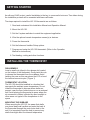
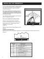
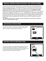
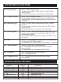
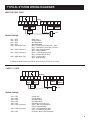
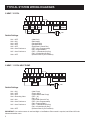
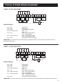
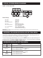
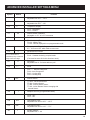
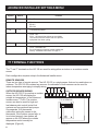
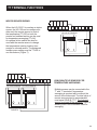
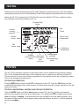
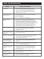
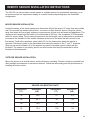
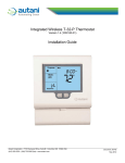
Installation Manual
Comfort System HG-122 Universal Thermostat
TM
O
Version 3.0
INTRODUCTION
This manual should not be left with the owner as it contains installer setup functions which, if not
correctly set, may cause damage to the HVAC equipment or seriously affect performance.
The HG-122 thermostat is intuitive, reliable and easy to install. Using a common sense approach to the
installation will ensure this product is installed properly and to the customer’s satisfaction. Please take
time to read and understand this manual so that installation and testing is performed in an efficient
manner.
This manual is to be used in conjunction with the supplied User Manual.
Although great care has been taken in the preparation of this manual, Heating Green takes no
responsibility for errors or omissions contained herein. It is the responsibility of the installer to
ensure that this thermostat and the equipment connected to it operate in a safe and efficient
manner.
Due to ongoing product improvements, Heating Green reserves the right to change the specifications
of the HG-122 thermostat or its components without notice.
All rights reserved.
© Heating Green 2010.
Intellectual rights apply.
1
GETTING STARTED
As with any HVAC project, careful installation is the key to a successful outcome. Time taken during
the installation process will be rewarded with fewer call-backs.
The steps required to install the HG-122 thermostat are as follows:
1. Read and understand this Installation Manual and Operation Manual.
2. Mount the HG-122.
3. Set the 8 system switches to match the equipment application.
4. Wire the optional remote temperature sensor(s) or devices.
5. Power the thermostat.
6. Set the Advanced Installer Setup options.
7. Program and setup the HG-122 thermostat. (Refer to the Operation
Manual for instructions)
8. Test heating, cooling and other functions.
INSTALLING THE THERMOSTAT
DISASSEMBLY
Insert a small coin (dime) in the release slot located
on the bottom of the thermostat. Gently twist the coin
to release the thermostat from the subbase. Avoid
twisting the case as this may stress the LCD or bend
the terminal connector pins. (Figure 1)
THERMOSTAT LOCATION
The HG-122 should be installed in a location that
represents the ambient space temperature. Do not
install the thermostat in an area where drafts are
present, near the floor, behind doors or on an external
wall. Avoid placing the thermostat in areas where the
air movement is limited, affected by direct sunlight or
other areas not typical of the temperature in the
space.
MOUNTING THE SUBBASE
When mounting the HG-122, be aware that drafts
may travel down wall cavities and enter the back of
the thermostat through the control wire hole in the
wall. It is important to seal the hole to prevent any
drafts that might affect the internal temperature
FIGURE 1
2
INSTALLING THE THERMOSTAT
Pull the control wires through the large opening in
the thermostat subbase. Next, level and mount
the subbase on the wall using the supplied
anchors and screws.
Do not over tighten the mounting screws as
the subbase may warp causing the improper
seating of the thermostat connecting pins to
the terminal blocks.
MOUNTING
HOLES
Use a properly sized screwdriver and land each
wire to its dedicated terminal.
Do not over tighten the terminal screws.
Check to ensure that all wires are landed
correctly and dressed properly to prevent any
shorts (refer to the “Typical System Wiring
Diagrams” in the manual).
(Figure 2)
FIGURE 2
Refer to Typical System Wiring Diagrams in this
manual.
TERMINAL DESIGNATIONS
Based on the HG-122 slide switch configurations, some terminals have multiple output functions.
(Figure 3)
FACTORY
JUMPER
W1
W2 Y2 O/B Y1 G
R
Power Coms Aux
24 24C B A T T
FIGURE 3
TERMINAL
W2
Y2
W1
O/B
Y1
G
R
24
24V
B
A
T
T
3
TERMINAL DESIGNATION CHART
DESIGNATION
Second Stage Heating or Auxiliary Heat
Second Stage Compressor
First Stage Heating
Reversing Valve
First Stage Compressor
Fan Relay
24 Volt Hot (Jumpered to ‘24’)
24 Volt Hot (Jumpered to ‘R’)
24 Volt Common
Modbus Communications
Modbus Communications
Auxiliary Input Terminal
Auxiliary Input Terminal
SPECIAL INSTRUCTIONS FOR DUAL FUEL APPLICATIONS
When the HG-122 is used with dual fuel systems, an outdoor sensor is recommended for balance
point control (Model HG-122-S1). The sensor is wired to the TT terminals on the thermostat. In the
Advanced Installer Settings, set TT = OA. This configures the thermostat to receive the outdoor
temperature information. High and low balance point settings are set in the Advanced Installer
Settings. HB = OFF is the factory default high balance point setting and LB = OFF is the factory
default low balance point setting. High balance point is adjustable from OFF to 32° F - 122° F and low
balance point is adjustable from OFF to 14° F - 77° F. When the outdoor temperature rises above the
high balance point setting, only first stage heat pump will be allowed to energize. When the outdoor
temperature falls below the low balance point setting, only the auxiliary heat will be energized and the
heat pump will be locked out. Typical settings might be 30° F Low Balance Point and 55° F High
Balance Point. High and low balance point control can also be used in conventional heat pump
applications.
The high balance point must be greater than the low balance point and there should be at
least a 5° F spread between the two.
ACTIVATING THE BATTERY
The HG-122 contains a 3 volt Lithium cell battery that maintains
the time of day in the event of a power failure. To activate the
battery, carefully remove the white tab. (Figure 4)
REMOVE TAB
ON
12345678
......
......
FIGURE 4
SETTING THE SYSTEM SWITCHES
The HG-122 contains a set of eight system switches located on
the thermostat printed circuit board. The switches are used to
match the thermostat with the specific type of HVAC system and
user preferences. Refer to the system switch functions to
properly configure the thermostat. (Figure 5)
ON
12345678
......
......
FIGURE 5
4
SYSTEM SWITCH FUNCTIONS
Sw1 - Equipment Type
Switch 1 sets the equipment type.
For heat / cool equipment, set the switch to the OFF position
(factory default).
For heat pump equipment, set the switch to the ON position.
Sw2 - Equipment Stages
Switch 2 sets the equipment stages.
For single stage equipment, set the switch to the OFF position
(factory default). For multi-stage equipment, set the switch to the
ON position.
Sw3 - Heat Pump Type
Switch 3 is used to select conventional heat pump or dual fuel
operation.
For conventional heat pump, set the switch to the OFF position
(factory default).
For dual fuel operation, set the switch to the ON position.
Sw4 - Reversing Valve
Switch 4 is used to select the heat pump reversing valve. For ‘O’
reversing valve (energize in cooling), set the switch to the OFF
position (factory default).
For ‘B’ reversing valve (energize in heating), set the switch to the
ON position.
Sw5 - Fan
Switch 5 is used to configure the fan operation. For gas systems,
set the switch to OFF (factory default).
For heat pump and electric systems, set the switch to ON position.
Sw6 - Thermostat Mode
Switch 6 is used to set the thermostat mode.
For non-programmable, set the switch to the OFF position
(factory default).
For programmable, set the switch to the ON position.
Sw7 - Schedules
OFF = 4 schedules per day (factory default).
ON = 2 schedules per day.
Sw8 - Compressor Delay
OFF = 4 minute short cycle protection (factory default).
ON = Disabled.
FACTORY DEFAULT SETTINGS
SWITCH
1 - Equipment Type
2 - Equipment tages
3 - Heat Pump Type
4 - Reversing Valve
5 - Fan
6 - Thermostat Mode
7 - Schedules
8 - Compressor Delay
5
ON/OFF
OFF
OFF
OFF
OFF
OFF
OFF
OFF
OFF
FUNCTION
Heat / Cool
Single Stage
Conventional Heat Pump
‘O’ Reversing Valve
Equipment Controls Fan
Non-programmable
4 Schedules per Day
4 Minute Short Cycle Protection Enabled
TYPICAL SYSTEM WIRING DIAGRAMS
HEAT OR COOL ONLY
W2
Y2
W1
O/B
G
Y1
HEAT 1
RELAY
24
R
24C
FAN 1
RELAY
B
A
MODBUS
COMP 1
RELAY
T
T
TT
TERMINALS
24 V
LINE
Switch Settings
Sw1 = OFF
Sw2 = OFF
Sw3 = OFF
Sw4 = OFF
Sw5 = Equipment Type
(Heat/Cool)
(Single Stage)
(Not Applicable)
(Not Applicable)
(OFF = Equipment Controls Fan - Gas)
(ON = Thermostat Control Fan - Electric)
(OFF = Non-Programmable)
(ON = Programmable)
(OFF = 4 Schedules per Day)
(ON = 2 Schedules per Day)
(OFF = Cooling Only)
(ON = Heating Only)
Sw6 = User Preference
Sw7 = User Preference
Sw8 = Application Type
In Advanced Installer Menu Set FN=H for Heat Only or FN=C for Cool Only
1 HEAT / 1 COOL
W2
Y2
W1
O/B
G
Y1
HEAT 1
RELAY
FAN 1
RELAY
COMP 1
RELAY
R
24
24C
B
A
MODBUS
24 V
T
T
TT
TERMINALS
LINE
Switch Settings
Sw1 = OFF
Sw2 = OFF
Sw3 = OFF
Sw4 = OFF
Sw5 = OFF
Sw6 = User Preference
Sw7 = User Preference
Sw8 = OFF
(Heat/Cool)
(Single Stage)
(Not Applicable)
(Not Applicable)
(Equipment Controls Fan)
(OFF = Non-Programmable)
(ON = Programmable)
(OFF = 4 Schedules per Day)
(ON = 2 Schedules per Day)
(4 Minute Short Cycle Protection)
6
TYPICAL SYSTEM WIRING DIAGRAMS
2 HEAT / 2 COOL
Y2
G2
W2
G3
W1
O/B
HEAT 2
RELAY
G1
Y1
HEAT 1
RELAY
COMP 2
RELAY
R
24
24C
B
FAN 1
RELAY
A
MODBUS
COMP 1
RELAY
T
T
TT
TERMINALS
LINE
24 V
Switch Settings
Sw1 = OFF
Sw2 = ON
Sw3 = OFF
Sw4 = OFF
Sw5 = OFF
Sw6 = User Preference
(Heat/Cool)
(Multi-stage)
(Not Applicable)
(Not Applicable)
(Equipment Controls Fan)
(OFF = Non-Programmable)
(ON = Programmable)
(OFF = 4 Schedules per Day)
(ON = 2 Schedules per Day)
(4 Minute Short Cycle Protection)
Sw7 = User Preference
Sw8 = OFF
2 HEAT / 1 COOL HEAT PUMP
W2
AUX
HEAT
Y2
W1
O/B
G
Y1
REV
VALVE
FAN 1
RELAY
COMP 1
RELAY
R
24
24C
B
A
MODBUS
24 V
T
T
TT
TERMINALS
LINE
Switch Settings
Sw1 = ON
Sw2 = OFF
Sw3 = OFF
Sw4 = Reversing Valve
Sw5 = ON
Sw6 = User Preference
Sw7 = User Preference
Sw8 = OFF
(Heat Pump)
(Single Stage)
(Conventional Heat Pump)
(OFF = ‘O’)
(ON = ‘B’)
(Thermostat Controls Fan)
(OFF = Non-Programmable)
(ON = Programmable)
(OFF = 4 Schedules per Day)
(ON = 2 Schedules per Day)
(4 Minute Short Cycle Protection)
IMPORTANT: If an outdoor sensor is used and High or Low Balance Point control is required, set HB and LB in the
Advanced Installer menu.
7
TYPICAL SYSTEM WIRING DIAGRAMS
3 HEAT / 2 COOL HEAT PUMP
W1
O/B
Y2
W2
AUX
HEAT
G
Y1
REV
VALVE
COMP 2
RELAY
R
24
24C
B
FAN 1
RELAY
A
MODBUS
COMP 1
RELAY
T
T
TT
TERMINALS
LINE
24 V
Switch Settings
Sw1 = ON
Sw2 = ON
Sw3 = OFF
Sw4 = Reversing Valve
(Heat Pump)
(Multi-stage)
(Conventional Heat Pump)
(OFF = ‘O’))
(ON = ‘B’)
(OFF = Non-Programmable)
(ON = Programmable)
(OFF = 4 Schedules per Day)
(ON = 2 Schedules per Day)
(4 Minute Short Cycle Protection)
Sw5 = ON
Sw7 = User Preference
Sw8 = OFF
IMPORTANT: If an outdoor sensor is used and High or Low Balance Point control is required, set HB and LB in the
Advanced Installer menu.
2 HEAT / 1 COOL DUAL FUEL
W2
FOSSIL
FUEL
Y2
W1
O/B
G
Y1
REV
VALVE
FAN 1
RELAY
COMP 1
RELAY
R
24
24C
B
A
MODBUS
24 V
T
T
TT
TERMINALS
LINE
Switch Settings
Sw1 = ON
Sw2 = OFF
Sw3 = ON
Sw4 = Reversing Valve
Sw5 = ON
Sw6 = User Preference
Sw7 = User Preference
Sw8 = OFF
(Heat Pump)
(Single Stage)
(Dual Fuel)
(OFF = ‘O’)
(ON = ‘B’)
(Thermostat Controls Fan)
(OFF = Non-Programmable)
(ON = Programmable)
(OFF = 4 Schedules per Day)
(ON = 2 Schedules per Day)
(4 Minute Short Cycle Protection)
IMPORTANT: An outdoor sensor is used for High or Low Balance Point. Set HB and LB in the Advanced Installer menu.
8
TYPICAL SYSTEM WIRING DIAGRAMS
3 HEAT / 2 COOL DUAL FUEL
W1
O/B
Y2
W2
FOSSIL
FUEL
REV
VALVE
COMP 2
RELAY
G
Y1
R
24
24C
FAN 1
RELAY
COMP 1
RELAY
B
A
MODBUS
T
T
TT
TERMINALS
24 V
LINE
Switch Settings
Sw1 = ON
Sw2 = ON
Sw3 = ON
Sw4 = Reversing Valve
Sw5 = ON
Sw6 = User Preference
Sw7 = User Preference
Sw8 = OFF
(Heat Pump)
(Multi-stage)
(Dual Fuel)
(OFF = ‘O’)
(ON = ‘B’)
(Thermostat Controls Fan)
(OFF = Non-Programmable)
(ON = Programmable)
(OFF = 4 Schedules per Day)
(ON = 2 Schedules per Day)
(4 Minute Short Cycle Protection)
IMPORTANT: If an outdoor sensor is used and High or Low Balance Point control is required, set HB and LB in the
Advanced Installer menu.
ENTERING THE ADVANCED INSTALLER SETTINGS MENU
The HG-122 contains factory defaults for all Advanced Installer Settings. Depending upon the user
and equipment application, some settings may need to be changed.
To enter the Advanced Installer Settings menu, push the O/RIDE button once, then hold it down (15
seconds) until the LCD displays LC which is the first menu item. You can move forward or backwards
through the menu by pressing the O/RIDE or PROG buttons.
ADVANCED INSTALLER SETTINGS MENU
Symbol
LC
Default
00
Keypad Lockout
Programmable Mode
(Sw6=ON)
LC=00 - All buttons are unlocked
LC=01 - All buttons are locked except ( ) ( ) buttons
LC=02 - All buttons are locked
LC
LC=00 - All buttons are unlocked
LC=02 - All buttons locked except ( ) ( ) buttons
LC=03 - PROG button is locked
LC=04 - All buttons are locked
00
Non-programmable
Mode
(Sw6=OFF)
9
Function
ADVANCED INSTALLER SETTINGS MENU
Symbol
Default
Function
HL
90
Maximum Heating Setpoint Limit
Adjustable from 41° F - 120° F
CL
50
Minimum Cooling Setpoint Limit
Adjustable from 43° F - 122°
CF
F
Temperature Display
CF=F - Fahrenheit
CF=C - Celsius
C1
0.0
Internal Sensor Calibration
Adjustable +/- 9° F in 0.2° F increments
TC
12
Time Format
TC=12 - 12 Hour Time
TC=24 - Military Time
TC=00 - No time displayed in non-programmable mode
AH
2
Temporary Hold Time for Programmable Mode
0.5 - 12 hours or OFF which holds to next event
FO
0
Advanced Fan Function
4 schedules per day = constant fan
in 1, 2, 3 and auto fan in 4
2 schedules per day = constant fan
in Day and auto fan in Night
FP
0
FN
---
FO=0 - No advanced fan function
FO=2 - Constant fan during occupied mode.
(Fan must be set to ON for this function to work)
Fan Purge
Adjustable from 0 - 5 minutes after any call
Mode
FN= - - - Manual Changeover
FN=A - Auto Changeover
FN=C - Cooling Only
FN=H - Heating Only
TT
OFF
Remote Sensor
TT=OFF - No Remote Sensor
TT=OA - Outdoor Sensor
TT=RS - Remote Indoor Sensor
TT=AU - Indoor Remote Sensor Averaging with
Internal Sensor
OS
1
Adaptive Recovery (Programmable Mode)
OS=0 - OFF
OS=1 - ON
HB
OFF
High Balance Point
Adjustable from OFF to 32° F - 122° F
LB
OFF
Low Balance Point
Adjustable from OFF to 14° F - 77° F
AD
1
Modbus Address
Adjustable from 1 - 99
10
ADVANCED INSTALLER SETTINGS MENU
Symbol
BD
Default
19.2
Function
Baud Rate
BD=4.8
BD=9.6
BD=19.2
CD
0
Commissioning Mode
CD=0 - OFF
CD=1 - All internal time delays are overridden
This function must be reset to CD=0 to prevent
equipment from short cycling
TS
0
Factory Test
TS=0 - Test Mode OFF
Do not change this function without reading the
Factory Test Mode instructions on Page 27
TT TERMINAL FUNCTIONS
The ‘T’ and ‘T’ terminals on the HG-122 are used for wiring either an indoor or an outdoor remote
sensor.
Each configuration requires setup in the Advanced Installer menu.
REMOTE SENSORS
There are two type of remote sensors. The HG-122-S1 is a single sensor that can be used indoors or
outdoors. The HG-122-S2 contains two sensors. A combination of both sensors can be used for
indoor temperature averaging to simplify wiring.
OUTDOOR SENSOR WIRING
When the HG-122-S1 is used as an outdoor
sensor, the HG-122 will display the
outside air temperature. In the Advanced
Installer menu, TT=OA. The outdoor
sensor can also be used for high and
low balance point control in dual fuel
systems and conventional heat pumps.
Use separate 18-2 thermostat
cable when wiring the sensor to the
thermostat. If the outdoor sensor fails, or
is not wired properly, two dashes will
appear on the LCD where the outside
temperature would normally be
displayed. (Figure 6)
11
W2
Y2
W1
O/B
Y1
G
R
24
T-32-S1 SENSOR
FIGURE 6
24C
B
A
T
T
TT TERMINAL FUNCTIONS
INDOOR SENSOR WIRING
W2
G3
When the HG-122-S1 is used as an indoor
sensor, the HG-122 can be configured to
allow only the remote sensor to control
the temperature (TT=RS) or both the
remote and onboard sensor can be used
for temperature averaging (TT=AV).
An optional in-line switch can also be
used with the remote sensor to change
the temperature sensing location from
remote to onboard sensor. The Advanced
Installer menu setting must be TT=RS to
use this feature. (Figure 7)
Y2
G2
W1
O/B
Y1
G1
R
24
24C
B
A
T
T
HG-122-S1 SENSOR
OPTIONAL
SWITCH
FIGURE 7
W2
G3
Y2
G2
W1
O/B
Y1
HG-122-S2 SENSOR
G1
R
24
24C
B
A
T
T
USING MULTIPLE SENSORS FOR
TEMPERATURE AVERAGING
HG-122-S2 SENSOR
Multiple sensors can be connected to the
‘T’ and ‘T’ terminals if temperature
averaging is required with or without the
sensor in the thermostat. The total value of
remote sensors wired in series/parallel
must equal 10kΩ @ 77º F. The onboard
sensor is not part of the equation. Figure 8
shows (2) HG-122-S2 sensors used for
averaging.
FIGURE 8
12
TESTING
Testing ensures that the thermostat and the HVAC equipment operate properly. Follow the detailed
testing steps and refer to the Troubleshooting Guide in this manual if any problems are encountered.
When the HG-122 is powered, the LCD will briefly show all available LCD icons, software version,
then display the time and operating mode, etc.
Program hold
active
Current
running
program
Day
Start Stop
Clock
System
mode
Fan
status
Set or room
temperature
System or
thermostat
fault
TIMER
Modbus
Keyboard
communications or control
active
limit
is locked
Outside air
temperature
Override timer
activated
Commissioning
mode
TESTING
The HG-122 incorporates a number of time delays which can be disabled during testing by setting
CD=1 in the Advanced Installer menu. After exiting the menu, a wrench icon will flash on the LCD.
This is to remind you that once testing is completed, the time delays need to be re-initiated by setting
CD=0 in the Advanced Installer menu.
TESTING FAN OPERATION
Pres the MODE button until the word OFF is displayed on the LCD. Press the FAN button and the
word Fan On will appear. After a brief moment, the internal fan relay will energize and the fan icon will
appear and rotate.
TESTING CONVENTIONAL HEATING AND COOLING OPERATION
Press the MODE button until Mode Heat appears on the LCD. Use the ( ) button and raise the
setpoint a few degrees above the space temperature. The heating relay will energize and the word
Heat will change to Heating. If the thermostat has been configured for multi-stage operation, raise
the setpoint further and the second stage heating relay will energize. A period ( . ) will be displayed
after the word Mode.
13
TESTING
Press the MODE button until Mode Cool appears on the LCD. Use the ( ) button and lower the
setpoint a few degrees below the space temperature. The cooling and fan relays will energize and the
word Cool will change to Cooling. If the thermostat has been configured for multi-stage operation,
lower the setpoint further and the second stage cooling relay will energize. A period ( . ) will be
displayed after the word Mode.
TESTING HEAT PUMP OPERATION
When the HG-122 is configured for heat pump operation, testing is the same as for a conventional
heating and cooling system with the exception that the fan relay is energized on a call for both
heating and cooling. Emergency Heat mode is only active when the thermostat MODE button is set to
emergency heat. E. Heat will be displayed on the LCD. When the W2 relay is energized E. Heating
will be displayed on the LCD.
When the thermostat is in the heat pump mode, the reversing valve is energized with a cooling call
‘O’ or heating call ‘B’, it will remain energized until there is an opposite call. If after 30 minutes there is
no call, the reversing valve will de-energize.
RESETTING THE TIME DELAYS
After testing the thermostat, change CD=1 to CD=0 in the Advanced Installer menu. This will be
confirmed when the flashing wrench icon no longer appears on the LCD.
FACTORY TEST MODE
The HG-122 contains a simple factory Test Mode that can confirm relay outputs, slide switch
configuration along with a factory default reset.
TS=0 - Factory Test Mode is OFF
TS=1 - Displays system configuration code based on slide switch settings
(for factory use only).
TS=2 - Cycles each relay on and off in an endless loop. Equipment should
be disabled when performing this test.
TS=3 - Resets software to factory defaults. Press Fan button to initiate.
ADAPTIVE RECOVERY
Adaptive Recovery is only available in programmable mode (Sw6=ON and OS=1). The Adaptive
Recovery function of the HG-122 permits the user to program a time that a desired set temperature is
required. The thermostat then calculates the most energy efficient time to bring on the equipment to
reach the setpoint at the designated time. This calculation involves a complex control algorithm that
compares the space temperature deviation from setpoint and rate of recovery history. “RECO”
flashes on the LCD when Adaptive Recovery is active.
14
BASIC TROUBLESHOOTING
SYMPTOM
POSSIBLE FAULT AND REMEDY
No LCD display
Remove thermostat from subbase and check for 24 Volts
across ‘24’ and ‘24C’. Make sure the factory jumper is between
‘R’ and ‘24’. If no voltage, check voltage at HVAC system
terminals ‘R’ and ‘C’. If no voltage, fault is equipment related. If
voltage, fault could be in wiring.
Thermostat can not be set
for auto changeover
In the Advanced Installer menu, set FN=A for auto changeover.
FN=C is for cooling only.
FN=H is for heating only.
FN= . . . is for manual heat / cool changeover.
Temperature display
inaccurate.
Air from the wall cavity may be leaking into the rear of the
thermostat. Seal holes in the wall to prevent air infiltration. The
temperature sensor might be folded back inside the thermostat
and is not being exposed to the room temperature. Carefully move
the sensor head so that it is just behind the sensor opening in the case.
External influence from appliances, lighting or drafts may be
affecting temperature accuracy. Move lamps or other sources of
abnormal temperature influence away from the thermostat.
Wrench icon flashes on LCD
This is not a fault. Commissioning mode is enabled and
time delays are overridden. Change CD=1 to CD=0 in the
Advanced Installer menu.
Outdoor temperature does not
display. Dashes (- - -) appear
on the LCD.
Check wiring to outdoor sensor. Make sure that TT=OA in
the Advanced Installer menu.
Heating or Cooling is flashing
This is not a fault. The thermostat is in the short cycle protection
mode. This prevents the equipment from running for
4 minutes after the thermostat calls.
Lock icon flashes when trying
to set a higher heating or
lower cooling temperature.
This is not a fault. HL and CL restrict the heating and cooling
setpoints. The limit values can be changed in the Advanced
Installer menu.
Thermostat displays wrong
temperature
The HG-122 can display in either Fahrenheit or Celsius. Change
CF=C or F in the Advanced Installer menu.
The fan continues to run after
a heating or cooling call is
satisfied.
The thermostat is set to Fan On. Set thermostat to Auto Fan.
The fan purge mode is set to run the fan for a fixed period of
time after the equipment shuts off. Change the FP value in the
Advanced Installer menu.
Some buttons on the
thermostat do not function.
Lock values have been set. Refer to LC settings in the
Advanced Installer menu.
Thermostat clock does not
keep proper time.
Make sure that the plastic tab on the internal fitted battery is
removed so that the battery is operational.
15
REMOTE SENSOR INSTALLATION INSTRUCTIONS
The HG-122 can use an indoor remote sensor or multiple sensors for temperature averaging, or as
an outdoor sensor for temperature display or a control function depending upon the thermostat
configuration.
INDOOR SENSOR INSTALLATION
Locate the sensor in the same manner as a thermostat. Mount the sensor 18” away from any outside
wall. Do not install the sensor behind doors, in corners or other dead air spaces. Keep the sensor
away from direct air flow, supply registers or near sources of heat such as lamps and appliances. The
maximum wire length from the sensor to the thermostat is 300 feet. Use a separate 18-2 thermostat
cable for sensor wiring. Prior to wiring the sensor to the thermostat, use an ohm-meter or multimeter
to measure the resistance of the sensor. Measure at the end of the wires that will connect to the
thermostat. Confirm the resistance value (within 5%) to the temperature where the sensor is
mounted. Disconnect power to the thermostat when wiring the sensor to the ‘T’ and ‘T’ terminals.
Strip only as much insulation off of the wires as necessary to provide a good contact with the
terminals. The sensor is not polarity specific so either sensor lead may be connected to either
terminal on the thermostat.
OUTDOOR SENSOR INSTALLATION
Mount the sensor on a vertical exterior surface below an overhang. Choose a location protected from
direct sunlight and exposure to excessive moisture. Follow the same wiring and test procedures as
installing an indoor sensor.
SENSOR CALIBRATION CHART
Temperature
(°F)
Resistance
(kΩ)
Temperature
(°F)
Resistance
(kΩ)
30
34.6
70
11.9
40
26.1
80
9.4
50
19.9
90
7.4
60
15.3
100
5.9
16
SPECIFICATIONS
Input Voltage
24 VAC 50/60 Hz
Relay Rating
24 VAC @ 1Amp maximum per relay
Operating Temperature
32° F to 122° F
Operating Relative Humidity
0-95% (non-condensing)
Storage Temperature
32° F to 105° F
Size
4-7/16” W x 4-1/16” H x 7/8” D
LCD Display Size
2-3/4” W x 1-7/8” H
Temperature Sensor
10K NTC type 3
Voltage
20-30 VAC
Resistance
10kΩ @ 77° F
Tolerance
+/- 3% @ 77° F
Stage Delays
Minimum temperature change over time
Timed Upstage Delay
5 - 90 minutes
Short-cycle Delay
Off to 4 minutes
Display Resolution
1° F
Control Range
41° F to 122° F or Heat Off / Cool Off
Outdoor Air Temperature Range
-10° F to 140° F
Back Light
Blue EL (Electro Luminescent)
Optimized Start/Stop Method
Time to start vs. temperature differential
Communications Protocol
Modbus
Approvals
FCC (Part 15) (Pending) C-tick
Warranty
5 years
17
06-1002-042210