1
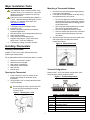
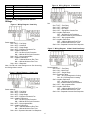
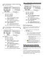
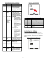
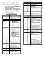
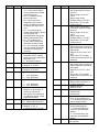
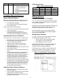
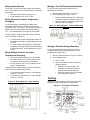
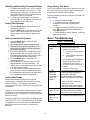
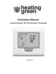
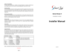
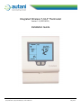
Integrated Wireless T-32-P Thermostat Version 1.4 (1000140-01) Installation Guide Autani Corporation • 7170 Riverwood Drive, Suite B • Columbia, MD 21046 USA (443) 320-2233 • (240) 755-0092 (fax) • www.autani.com Document: 80142 May 2012 Contents List of Figures Major Installation Tasks .................................................. 3 Figure 1. Opening the T-32-P ........................................ 3 Installing Thermostats ..................................................... 3 Figure 2. Subbase Mounting .......................................... 3 Locating Thermostats .................................................. 3 Figure 3. Terminal Designations .................................... 3 Opening the Thermostat ............................................. 3 Figure 4. Wiring Diagram: Heat Only ............................ 4 Mounting a Thermostat Subbase ................................ 3 Figure 5. Wiring Diagram: 1 Heat/1 Cool ...................... 4 Terminal Designations................................................. 3 Figure 6. Wiring Diagram: 2 Heat/2Cool ....................... 4 Typical Wiring Diagrams and Switch Settings ............ 4 Figure 7. Wiring Diagram: 2 Heat/1 Cool Heat Pump... 4 Dual Fuel Applications................................................. 5 Figure 8. Wiring Diagram: 3 Heat/2 Cool Heat Pump... 5 Setting the System Switches........................................... 5 Figure 9. Wiring Diagram: 2 Heat/1 Cool Dual Fuel ..... 5 Activating the Battery ...................................................... 6 Figure 10. Wiring Diagram: 3 Heat/2 Cool Dual Fuel ... 5 Accessing the Settings Menu .......................................... 7 Figure 11: System Switches .......................................... 6 Installing Remote Sensors .............................................. 9 Figure 12. Removing the Battery Tab ............................ 6 Types of Remote Sensors ........................................... 9 Figure 13. Wiring Diagram: Outdoor Sensor ................ 9 Installing Indoor Sensor Guidelines ............................ 9 Figure 14. Wiring Diagram: Indoor Sensors ............... 10 Installing Outdoor Sensor Guidelines.......................... 9 Figure 15. Wiring Diagram: Turning Off Sensors Calibrating Sensors ..................................................... 9 Remotely ................................................... 10 Wiring Sensors ................................................................ 9 Figure 16. Thermostat LCD Display ............................ 10 Function Overview for ‘T’ Terminals ............................ 9 Wiring Outdoor Sensors .............................................. 9 Wiring Indoor Sensors ............................................... 10 List of Tables Wiring Sensors for Indoor Temperature Averaging .. 10 Table 1. Terminal Designation Chart ............................. 3 Wiring Multiple Sensors for Indoor Temperature Averaging ............................................................ 10 Table 2. Switch Functions and Settings ........................ 6 Wiring to Turn Off Thermostats Remotely................. 10 Table 3. Factory Default Switch Settings ....................... 6 Wiring to Override Settings Remotely ....................... 10 Table 4. Settings Menu Options .................................... 7 Testing........................................................................... 10 Table 5. Sensor Calibration Chart ................................. 9 Disabling and Resetting Thermostat Delays ............. 11 Table 6. Troubleshooting ............................................. 11 Testing Fan Operation............................................... 11 Table 7. T-32-P Specifications ..................................... 12 Testing Conventional Systems .................................. 11 Testing Heat Pumps .................................................. 11 Using Factory Test Mode .......................................... 11 Basic Troubleshooting ................................................... 11 Specifications ................................................................ 12 Legal Notice .................................................................. 12 2 Major Installation Tasks Mounting a Thermostat Subbase This Installation Guide contains installer setup functions which, if not correctly set, may cause damage to the HVAC equipment or seriously affect performance. There are no user-serviceable parts inside the T-32-P. Unauthorized dismantling will void the warranty. For warranty information, see www.autani.com/legal. 1. Pull the control wires through the large opening in the thermostat subbase. 2. Level and mount the subbase on the wall using the supplied anchors and screws. 1. Thoroughly read this Installation Guide. 2. Install the T-32-P. 3. Set the eight system switches to match the equipment application. 4. Wire the optional remote temperature sensor(s). 5. Power the thermostat. 6. Select options in the Settings menu. 7. Program and setup the T-32-P thermostat. Refer to the T-32-P User’s Manual. 8. Test heating, cooling, and other functions. Do not over tighten the mounting screws as the subbase may warp causing the improper seating of the thermostat connecting pins to the terminal blocks. Use a properly sized screwdriver to connect each wire to its dedicated terminal. Do not over tighten the terminal screws. Check to ensure that all wires are connected correctly and dressed properly to prevent any shorts. 3. Seal the control wire hole to prevent drafts in the wall cavities that can affect the internal temperature sensor. Figure 2. Subbase Mounting Installing Thermostats Locating Thermostats Install the T-32-P in a location that represents the ambient space temperature. Do not install thermostats on an external wall or in areas: Where air movement is limited Affected by direct sunlight Near lamps or appliances Where there may be drafts Near the floor Behind doors Terminal Designations Opening the Thermostat Based on the T-32-P slide switch configuration, some terminals have multiple output functions. 1. Insert a small coin (such as a dime) in the release slot located on the bottom of the thermostat. 2. Gently twist the coin to release the thermostat from the subbase. Figure 3. Terminal Designations Avoid twisting the case to protect the LCD screen and avoid bending the terminal connector pins. Figure 1. Opening the T-32-P Table 1. Terminal Designation Chart Terminal W2 Y2 W1 O/B Y1 G1 R 3 Designation Second stage heating or auxiliary heat Second stage compressor First state heating Reversing Valve First stage compressor Fan relay 24 volt hot (jumpered to ‘24’) Terminal 24 24C B A T T Figure 6. Wiring Diagram: 2 Heat/2Cool Designation 24 volt hot 24 volt common Modbus communications Modbus communications Auxiliary input terminal Auxiliary input terminal Typical Wiring Diagrams and Switch Settings Switch Settings Sw1 = OFF – Fan Relay Sw2 = OFF – Heat/Cool Sw3 = ON – Two Stage Sw4 = OFF – Equipment Controls Fan Sw5 = Installer Preference OFF – No Short Cycle Protection ON – 4 Minute Short Cycle Protection Sw6 = OFF – Non-programmable Sw7 = Installer Preference OFF – 2 Minute Minimum Run Time ON – 6 Minute Minimum Run Time Sw8 = ON – Separate Heat and Cool Setpoints Figure 4. Wiring Diagram: Heat Only Switch Settings Sw1 = OFF – Fan Relay Sw2 = OFF – Heat/Cool Sw3 = OFF – Single Stage Sw4 = OFF – Equipment Controls Fan Sw5 = Installer Preference OFF – No Short Cycle Protection ON – 4 Minute Short Cycle Protection Sw6 = OFF – Non-programmable Sw7 = Installer Preference OFF – 2 Minute Minimum Run Time ON – 6 Minute Minimum Run Time Sw8 = ON – 2 Setpoints Figure 7. Wiring Diagram: 2 Heat/1 Cool Heat Pump Note: Set FN to H in the Settings menu. See Accessing the Settings Menu section. Switch Settings Sw1 = OFF – Fan Relay Sw2 = ON – Heat Pump Sw3 = OFF – Single Stage Sw4 = Reversing Valve OFF – O = RV Energized in Cooling ON – B = RV Energized in Heating Sw5 = Installer Preference OFF – No Short Cycle Protection ON – 4 Minute Short Cycle Protection Sw6 = OFF – Non-programmable Sw7 = Installer Preference OFF – 2 Minute Minimum Run Time ON – 6 Minute Minimum Run Time Sw8 = ON – Separate Heat and Cool Setpoints Figure 5. Wiring Diagram: 1 Heat/1 Cool Switch Settings Sw1 = OFF – Fan Relay Sw2 = OFF – Heat/Cool Sw3 = OFF – Single Stage Sw4 = OFF – Equipment Controls Fan Sw5 = Installer Preference OFF – No Short Cycle Protection ON – 4 Minute Short Cycle Protection Sw6 = OFF – Non-programmable Sw7 = Installer Preference OFF – 2 Minute Minimum Run Time ON – 6 Minute Minimum Run Time Sw8 = ON – Separate Heat and Cool Setpoints 4 Figure 10. Wiring Diagram: 3 Heat/2 Cool Dual Fuel Figure 8. Wiring Diagram: 3 Heat/2 Cool Heat Pump Switch Settings Sw1 = OFF – Fan Relay Sw2 = ON – Heat Pump Sw3 = ON – Two Stage Sw4 = Reversing Valve OFF – O = RV Energized in Cooling ON – B = RV Energized in Cooling Sw5 = Installer Preference OFF – No Short Cycle Protection ON – 4 Minute Short Cycle Protection Sw6 = OFF – Non-programmable Sw7 = Installer Preference OFF – 2 Minute Minimum Run Time ON – 6 Minute Minimum Run Time Sw8 = ON – Separate Heat and Cool Setpoints Switch Settings Sw1 = OFF – Fan Relay Sw2 = ON – Heat Pump Sw3 = ON – Two Stage Sw4 = Reversing Valve OFF – O = RV Energized in Cooling ON – B = RV Energized in Cooling Sw5 = Installer Preference OFF – No Short Cycle Protection ON – 4 Minute Short Cycle Protection Sw6 = OFF – Non-programmable Sw7 = Installer Preference OFF – 2 Minute Minimum Run Time ON – 6 Minute Minimum Run Time Sw8 = ON – Separate Heat and Cool Setpoints Dual Fuel Applications When the T-32-P is used with dual fuel systems, an outdoor sensor is recommended for balance point control. Figure 9. Wiring Diagram: 2 Heat/1 Cool Dual Fuel 1. Wire the sensor to the ‘T’ terminals on the thermostat. 2. In the Settings menu: a. Set TT to OA to configure the thermostat to receive outdoor temperature information. b. Select high and low balance point settings. Switch Settings Sw1 = OFF – Fan Relay Sw2 = ON – Heat Pump Sw3 = OFF – Single Stage Sw4 = Reversing Valve OFF – O = RV Energized in Cooling ON – B = RV Energized in Cooling Sw5 = Installer Preference OFF – No Short Cycle Protection ON – 4 Minute Short Cycle Protection Sw6 = OFF – Non-programmable Sw7 = Installer Preference OFF – 2 Minute Minimum Run Time ON – 6 Minute Minimum Run Time Sw8 = ON – Separate Heat and Cool Setpoints c. High balance point range is 32°F-122°F. Factory default is 55°F. Low balance point range is 15°F-77°F. Factory default is 35°F. Configure the W2 relay to lock out the heat pump at the low balance point or whenever the thermostat calls for auxiliary or emergency heat. Set H3 to FF. Setting the System Switches The T-32-P printed circuit board contains a set of eight system switches. The switches are used to match the thermostat with the type of system being used and user preferences. The function of each switch is described in the table below. For information on switch settings by specific system configuration, see the section entitled Typical Wiring Diagrams and Switch Settings. 5 Table 2. Switch Functions and Settings Switch Sw1 Function Fan Relay Sw2 Equipment Configuration Sw3 Equipment Stages Sw4 Fan Mode for heat/cool systems Reversing valve for heat pumps Figure 11: System Switches Setting Leave switch in OFF position (factory default). Heat/cool equipment: leave switch in OFF position (factory default). Heat pump: Set switch to ON position. Single stage equipment: leave switch in OFF position (factory default). Multistage equipment: Set switch to ON position. Fan mode Table 3. Factory Default Switch Settings Gas or oil systems (equipment controls fan in heating mode): leave switch in OFF position (factory default). Electric systems (thermostat controls fan in heating mode): set switch to ON position. Switch Sw1 Sw2 Sw3 Sw4 Sw5 Sw6 Sw7 Sw8 Default OFF OFF OFF OFF ON OFF OFF ON Function Fan relay Heat/cool equipment Equipment stages Fan control/Reversing valve Four minute short cycle protection Non-programmable Two minute minimum run time Separate heating and cooling setpoints Reversing Valve Sw5 Short Cycle Timer Sw6 Thermostat Operation Sw7 Minimum Run Time Sw8 Program Schedule “O” reversing valve (energize cooling): leave switch in OFF position (factory default). “B” reversing valve (energize heating): set switch to ON position. Activating the Battery The T-32-P contains a 3 volt lithium cell battery that maintains the time of day in the event of a power failure. If there is a white tab, carefully remove it to activate the battery. Figure 12. Removing the Battery Tab Leave switch in ON position for four minute short cycle protection (factory default). Leave switch in OFF position for nonprogrammable mode (factory default). Leave switch in OFF position for two minute minimum run time (factory default). Leave switch in ON position for separate heating and cooling setpoints (factory default). 6 Accessing the Settings Menu 1. Press the O/RIDE button once and hold it down until the number “88:15” is displayed on the LCD screen (about 15 seconds). 2. Using the arrow button, adjust the value until it reads “88:32” and then press the O/RIDE button to enter the menu. 3. To navigate through the menu, press the O/RIDE button to move forward or the PROG button to move backwards. Default 32 LC 00 Programmable Mode (Sw6=ON) Manual Mode (Sw6=OFF) HL 90 CL 50 CF F C1 0.0 Default 12 TD 0 AH 2.0 4 Schedules (Sw6=ON) (Sw8=ON) Table 4. Settings Menu Options Symbol PN Symbol TC Function/Setting Options Keyboard Lock PIN. PIN is required to enter the Settings menu. Range is 00-99. Keyboard Lock OFF All buttons are locked except: 01 – ▲and▼ buttons 02 – O/RIDE and ▲and▼ 03 – MODE, O/RIDE and ▲and▼ 04 – MODE and ▲and▼ 05 – O/RIDE 06 – All buttons are locked. 00 – Keyboard lock OFF 01 – All buttons are locked except MODE. 02 – All buttons are locked except MODE and ▲and▼. 03 – FAN and PROG are locked. MODE button can only select Auto or OFF. 04 – MODE button can only select Auto or OFF. 05 – All buttons are locked. 06 – All buttons are locked. Maximum heating or high temperature limit Range using LCD is 41°F120°F. Range using Autani EnergyCenter is 41°F-98°F. Minimum cooling or low temperature limit Range using LCD is 43°F122°F. Range using Autani EnergyCenter is 43°F-98°F. Temperature Display Degrees F or C Internal Sensor Calibration Range is +/- 9°F, in increments of tenths of a degree. 7 SC SH DB FO OF OF 2 0 FP 0 FN A H3 OF Function/Setting Options Time Format 12 or 24 Hour Clock 0 – Displays set and space temperatures. 1 – Displays only the set temperature. After hours override timer Range is OFF to 12, in increments of half an hour. Temporary program override 0 (OFF) extends override until the next program change. Range is 1-12 override hours. Factory default – Do not change. Factory default – Do not change. Factory default – Do not change. 0 – Fan runs continuously in ON mode. 1 – Fan continues to run after cooling cycle but not heating cycle. 2 – In programmable mode (Sw6=ON), fan runs continuously with program 1 through 4 and then in AUTO from program 4 through 1. 3 – In programmable mode (Sw6=ON), fan control is a combination of options 1 and 2. Fan Purge Range is 0-5 minutes after heating or cooling cycle A – Mode for heating/cooling system C – Cooling only system H – Heating only system OF – W2 relay only operates as auxiliary heat in heat pump mode (Sw1=OFF; Sw2=ON). EH – W2 relay controls emergency heat. AH – Do not use this function. AL – W2 relay used for auxiliary and emergency heat. FF – Fossil Fuel (Y is locked out when W2 is energized.) Symbol TT Default RS AF 1 OH OF OC OF SP 2 SD 2 DT 20 OS 1 C2 0.0 Function/Setting Options RS – For NO remote sensor or 1 or more remote indoor sensors without the onboard sensor being used OA – For outdoor remote sensor connection DA – Sends measured temperature from remote sensor via Modbus but does not display the value on the LCD. OC – For connecting dry contact switch used to replace user set points with preprogrammed cooling and heating setpoints (OC/OH) OF – For connecting dry contact switch used to turn thermostat off when closed AV – For combined average from the internal thermostat sensor and remote indoor sensor(s) 1 – Freeze protection ON. If thermostat is OFF, heating comes on if room temperature falls below 41°F. 0 – No freeze protection Override heating setpoint Range is 41°F-120°F. Override cooling setpoint Range is 43°F-122°F. 2 – 1.9° F differential for stage 1 1 – 1.4°F differential 3 – 2.4°F differential 2 – 1.9°F differential for stage 2 1 – 1.4°F differential 3 – 2.4°F differential Upstage timer Range is 10-90 minutes, in five minute increments. Only works if thermostat has not called for second or third stage and Sw3=ON. 1 – Adaptive Recovery ON 0 – Adaptive Recovery OFF Remote sensor calibration Range is +/- 9°F, in increments of half a degree. 8 Symbol CO Default 55 HO 75 HB 55 LB 35 FT OF AD 1 BD 19.2 CD 0 SS 0 RS 50 Function/Setting Options When outdoor temperature falls below setpoint, cooling shuts off. Range using LCD is 43°F122°F. Range using Autani EnergyCenter is 43°F-98°F. Only works if TT=OA with outdoor sensor. When outdoor temperature rises above setpoint, heating shuts off. Range using LCD is 41°F120°F. Range using Autani EnergyCenter is 41°F-98°F. Only works if TT=OA with outdoor sensor. High Balance Point W2 auxiliary heat is locked out when temperature rises above HB setpoint. Options are 32°F-122°F and OFF. Only works if TT=OA with outdoor sensor and H3=FF for fossil fuel. Low Balance Point W2 auxiliary heat is locked out when temperature falls below LB setpoint. Options are 14°F-77°F and OFF. Only works if TT=OA with outdoor sensor and H3=FF for fossil fuel. Replace or clean filter Range is Off to 90 hours, in 10 hour increments. Modbus Address Must be set to 1. 19.2 baud rate 9.6 baud rate 4.8 baud rate 0 – Commissioning Mode OFF; all time delays active 1 – Commissioning Mode ON; all time delays inactive 0 – Start/Stop mode controlled by thermostat program 1 – Thermostat Start only mode per call by Modbus Master 2 – Thermostat Stop only mode per call by Modbus Master Response Time – Do not change factory default. Symbol TS Default 0 Calibrating Sensors Function/Setting Options 0 – Factory Test Mode OFF 1 – Display configuration code 2 – Step cycle all relays in sequence 3 – Reset software to factory defaults (Press the Fan button to initiate.) Table 5. Sensor Calibration Chart Temperature (F°) 30 40 50 60 Installing Remote Sensors For temperature averaging As an outdoor sensor for temperature display As a control function The T-32-S1 is a single sensor that can be used indoors or outdoors. The T-32-S2 contains two sensors. A combination of both sensors can be used for indoor temperature averaging to simplify wiring. Each configuration requires setup using the Setting menu. For more information, see the section entitled Accessing the Settings Menu. Wiring Outdoor Sensors To use the T-32-S1 as an outdoor sensor and display the outside air temperature on the T-32-P: Locate the sensor in the same manner as a thermostat. Mount the sensor 18” away from outside walls. Do not install the sensor behind doors, in corners or other dead air spaces. Keep the sensor away from direct air flow, supply registers, or sources of heat such as lamps and appliances. The maximum wire length from the sensor to the thermostat is 300 feet. Use a separate 18-2 thermostat cable for sensor wiring. Prior to wiring the sensor to the thermostat, use an ohm-meter or multimeter to measure the resistance of the sensor. Measure at the end of the wires that will connect to the thermostat. Confirm the resistance value (within 5%) to the temperature where the sensor is mounted. Disconnect power to the thermostat when wiring the sensor to the T terminals. Strip only as much insulation off the wires as necessary to provide a good contact with the terminals. The sensor is not polarity specific so either sensor lead may be connected to either terminal. 1. Wire the sensor to the thermostat as shown using separate 18-2 thermostat cable. 2. In the Settings menu, set TT to OA. If the outdoor sensor fails, or is not wired properly, two dashes will appear on the LCD where the outside temperature would normally be displayed. The outdoor sensor can also be used for high and low balance point control in dual fuel systems. For more information, see the Dual Fuel Applications section. Figure 13. Wiring Diagram: Outdoor Sensor Installing Outdoor Sensor Guidelines 11.9 9.4 7.4 5.9 Depending on the thermostat configuration, the terminals can also be used for other functions such as remote ON/OFF switching of various control functions. Installing Indoor Sensor Guidelines 70 80 90 100 The ‘T’ terminals on the thermostat are primarily used to wire an indoor or outdoor remote sensor. The terminals are not polarity dependent. There are two types of remote sensors. 34.6 26.1 19.9 15.3 Resistance (10kΩ) Function Overview for ‘T’ Terminals Depending on the thermostat configuration, the T-32-P can use an indoor remote sensor or multiple sensors: Temperature (F°) Wiring Sensors Types of Remote Sensors Resistance (10kΩ) Mount the sensor on a vertical exterior surface below an overhang. Choose a location protected from direct sunlight and exposure to excessive moisture. Follow the same wiring and test procedures as installing an indoor sensor. 9 Wiring Indoor Sensors Wiring to Turn Off Thermostats Remotely To use the T-32-S1 as an indoor sensor and configure the T-32-P to allow only the remote sensor to control the temperature: To use an external dry contact switch to turn a thermostat off remotely: 1. Wire the switch as shown in Figure 16. 2. In the Settings menu, set TT to OF. 1. Wire the sensor as shown in Figure 13. 2. In the Settings menu, set TT to RS. Wiring Sensors for Indoor Temperature Averaging To use temperature averaging with or without the thermostat onboard sensor, multiple sensors can be connected to the ‘T’ terminals. The total value of remote sensors wired in series/parallel must equal 10kΩ @ 77°F. The onboard sensor is not part of the equation. When the switch is closed, the T-32-P turns off and the word OFF flashes on the LCD. When the switch is opened, the thermostat returns to the user settings. Figure 15. Wiring Diagram: Turning Off Sensors Remotely To use a single T-32-S1 as an indoor sensor, wire the sensor as shown in Figure 13. To use both the remote and onboard sensor for temperature averaging, in the Settings menu set TT to AV. To use an optional in-line switch to change the temperature sensing location from the remote to the onboard sensor, in the Settings menu set TT to RS. Wiring to Override Settings Remotely To use an external dry contact switch to remotely change the heating and cooling setpoints to a preprogrammed override value: Wiring Multiple Sensors for Indoor Temperature Averaging 1. Wire the switch as shown in Figure 16 above. See Figure 14 for wiring two T-32-S2 sensors. For three sensors, one T-32-S2 and two T-32S1 sensors can be wired in series/parallel. For four sensors, four T-32-S1 sensors can be wired in series/parallel. 2. In the Settings menu: a. Set TT to OC. b. Use OC and OH to set the cooling and heating setpoints. Configurations of multiple sensors can be used with or without the thermostat onboard sensor. To include the onboard sensor, in the Settings menu set TT to AV. To exclude the onboard sensor, in the Settings menu set TT to RS. When the switch is closed, user setpoints are replaced by the preprogrammed override setpoints. When the switch is open, thermostat user settings are restored. Testing When the T-32-P is powered, the LCD screen briefly displays important information as shown below. Figure 14. Wiring Diagram: Indoor Sensors Figure 16. Thermostat LCD Display 10 Disabling and Resetting Thermostat Delays Using Factory Test Mode 1. To disable time delays in the T-32-P to facilitate testing, in the Settings menu set CD to 1. After exiting the menu, a wrench icon flashes on the LCD screen as a reminder to reinstate the time delays when testing is completed. 2. To reinstate the time delays, in the Settings menu set CD to 0. The flashing wrench icon no longer appears on the LCD screen. The T-32-P contains a simple factory test mode that can be used to confirm relay outputs, switch configurations, or reset the thermostat to factory defaults. Access the Settings menu and select one of following TS switch settings: Testing Fan Operation 1. Press the MODE button until the word OFF is displayed on the LCD. 2. Press the FAN button and the words Fan On will appear. After a brief moment, the internal fan relay energizes and the fan icon appears and rotates. Testing Conventional Systems 0 – Factory Test Mode is OFF. 1 – For factory use only. Displays system configuration code based on slide switch settings. 2 – Cycles each relay on and off in an endless loop. Equipment should be disabled when performing this test. 3 – Reset software to factory defaults. Press the Fan button to initiate. Basic Troubleshooting 1. Press the MODE button until Mode Heat appears on the LCD. 2. Use the ▲ button to raise the setpoint a few degrees above the space temperature. The heating relay will energize and the word Heat will change to Heating. 3. If the thermostat has been configured for multistage operation, raise the setpoint further and the second stage heating relay energizes and a period is displayed after the word Mode. 4. Press the MODE button until Mode Cool appears on the LCD. 5. Use the ▼ button to lower the setpoint a few degrees below the space temperature. The cooling and fan relays will energize and the word Cool will change to Cooling. 6. If the thermostat has been configured for multistage operation, lower the setpoint further and the second stage cooling relay energizes and a period is displayed after the word Mode. Table 6. Troubleshooting Symptom No LCD Display Potential Solution 1. Remove thermostat from subbase and check: a. For 24 volts across ‘24’ and ‘24C’ b. Factory jumper is between ‘R’ and ‘24”. 2. If no voltage, check voltage on HVAC for 24 volts at HVAC system terminals ‘R’ and ‘C’. If no voltage, fault is equipment related. 3. If voltage, check wiring. “Locked” appears on LCD screen and heating or cooling not operating Testing Heat Pumps When the thermostat is in heat pump mode, the reversing valve is energized when it receives a call for cooling or heating. The reversing valve remains energized for 30 minutes unless there is an opposite call in the interim. Wrench icon flashes on LCD Testing a T-32-P configured for heat pumps is the same as testing for a conventional heating and cooling system except the fan relay is energized on a call for heating as well as for cooling. Some thermostat buttons do not function Emergency Heat mode is active when the thermostat H3 setting is EH, FF or AL in the Settings menu. E. Heating is displayed on the LCD when either the thermostat is placed in emergency heat mode or the W2 relay is energized. 11 If an outdoor sensor is being used, it could be preventing heating or cooling calls. Adjust the appropriate setting in the Settings menu if the outdoor air temperature is: Close to the OFF setpoint for heating or cooling Above the heating OFF setpoint Below the cooling OFF setpoint Commission mode is enabled and time delays are being overridden. Change CD to 0 in Settings menu. Lock values have been set. Refer to LC settings in the Settings menu. Symptom Temperature display inaccurate Outdoor temperature does not display (Dashes appear on the LCD screen) “Heating” or “Cooling” is flashing while the HVAC system is running Lock icon flashes when trying to set a higher heating or lower cooling temperature Thermostat displays wrong temperature scale Fan continues to run after a heating or cooling call is satisfied Thermostat clock does not keep proper time Potential Solution Air from the wall cavity may be leaking into the rear of the thermostat. Seal holes in the wall to prevent air infiltration. The temperature sensor might be folded back inside the thermostat and is not being exposed to the room temperature. Carefully move the sensor head so that it is just behind the sensor opening in the case. External influences from appliances, lighting or drafts may be affecting temperature accuracy. Move lamps or other sources of abnormal temperature influence away from the thermostat. Check wiring to outdoor sensor. Make sure that TT=OA in the Settings menu. Specifications Table 7. T-32-P Specifications Input Voltage Relay Rating Operating Temperature Operating RH Storage Temperature Size LCD Display Size Temperature Sensor Voltage Resistance Tolerance Stage Delays Timed Upstage Delay Short-cycle Delay Display Resolution Control Range Outdoor Air Temperature Range Back Light The T-32-P has a built-in minimum equipment run time of either 2 or 6 minutes. Sw6 may be set for 6 minutes (ON) which is keeping the equipment on after the thermostat reaches setpoint. HL and CL restrict the heating and cooling setpoints. The setpoints can be changed in the Settings menu. Optimized Start/Stop Method Communications Protocol Approvals Warranty 24 VAC 50/60 Hz 24 VAC @ 1Amp maximum per relay 32°F to 122°F 0-95% (non-condensing) 32°F to 105°F 4-7/16” W x 4-1/16” H x 7/8” D 2-3/4” W x 1-7/8” H 10K NTC type 3 20-30 VAC 10kΩ @ 77°F +/- 3% @ 77°F Minimum temperature change over time 5 to 90 minutes Off to 4 minutes 0.1° F Off to 105°F -10°F to 140°F Blue EL (Electro Luminescent) Time to start vs. temperature differential Modbus FCC (Part 15) (Pending) 5 years Legal Notice The T-32-P can be configured to use the Fahrenheit or Celsius scale. Change CF to C or F in the Settings menu. The thermostat is set to Fan ON. Set the thermostat to Auto Fan. The fan purge mode is set to run the fan for a fixed period of time after the equipment shuts off. Change the FP value in the Settings menu. Make sure the plastic tab on the internal battery has been removed so that the battery is operational. Copyright Autani Corporation, 2010-2012. All rights reserved. Please refer to www.autani.com/legal for licensing, intellectual property, and other legal notices and information. 12