1
YASRT Raytracer
YASRT Version 0.1 Beta 14
User's Documentation
Last Updated: October, 10th 2002
Copyright 2000/2002 Emmanuel Viale
______________________________________________________________________
Abstract:
This document is the user’s manual for the YASRT Raytracer. It describes what
YASRT is and what it’s not. It walks the reader through a tutorial that shows the
main features of the program. A full documentation on the YASRT language is
also given. All tools that are part of the package are also described in this
document.
______________________________________________________________________
Table of Contents
Introduction ...................................................................................................................... 4
What is it?...................................................................................................................... 4
What is raytracing? ...................................................................................................... 4
What is radiosity? ........................................................................................................ 5
Current Features........................................................................................................... 5
Future Features............................................................................................................. 8
Installation Notes ......................................................................................................... 9
Windows ................................................................................................................... 9
PocketPC ................................................................................................................... 9
Linux .......................................................................................................................... 9
DEC UNIX............................................................................................................... 10
HP-UX...................................................................................................................... 10
AIX ........................................................................................................................... 10
FreeBSD ................................................................................................................... 10
Solaris....................................................................................................................... 10
Irix ............................................................................................................................ 10
BeOS ......................................................................................................................... 10
MacOS X .................................................................................................................. 10
Tutorial ............................................................................................................................ 11
YASRT language features ......................................................................................... 11
Environment ............................................................................................................... 11
Camera......................................................................................................................... 11
Lights ........................................................................................................................... 11
Textures ....................................................................................................................... 11
Primitives .................................................................................................................... 11
YASRT Command-Line Options ................................................................................. 12
Input and Output File Options ................................................................................ 12
Input File ................................................................................................................. 12
Output File .............................................................................................................. 12
Raytracing Options .................................................................................................... 13
Advanced Options ..................................................................................................... 14
Multi-Threading ..................................................................................................... 15
3DS File Support .................................................................................................... 15
Priority Queue Size................................................................................................ 16
Language Syntax ............................................................................................................ 17
File types ..................................................................................................................... 17
Input files ................................................................................................................ 17
Output files ............................................................................................................. 17
File inclusions ......................................................................................................... 18
Data types.................................................................................................................... 18
Integers .................................................................................................................... 18
Floats ........................................................................................................................ 18
Colors....................................................................................................................... 19
Vectors ..................................................................................................................... 19
Strings ...................................................................................................................... 20
Variable declarations ............................................................................................. 20
3DS File Support ........................................................................................................ 21
Environment ............................................................................................................... 23
Camera......................................................................................................................... 26
Lights ........................................................................................................................... 29
Textures ....................................................................................................................... 33
Primitives .................................................................................................................... 37
Sphere ...................................................................................................................... 37
Plane......................................................................................................................... 38
Polygon.................................................................................................................... 40
Triangle.................................................................................................................... 41
Smooth triangle (patch)......................................................................................... 43
Ring .......................................................................................................................... 45
Disc........................................................................................................................... 47
Cone ......................................................................................................................... 48
Cylinder................................................................................................................... 50
Tools................................................................................................................................. 52
The 3DS file conversion utility: 3ds2yst.................................................................. 52
The 3DS file pre-viewer and converter: gl3ds2yst ................................................ 52
Future Tools ................................................................................................................ 56
______________________________________________________________________
Introduction
This section presents the YASRT Raytracer. The main features are listed, along
with current and future features. The section ends with installation notes for the
different platforms supported.
What is it?
YASRT is a raytracing program. It uses the raytracing algorithm to generate
realistic pictures from textual descriptions of three-dimensional scenes. It uses
the metaphor of photography to achieve this goal. The photographer (the user of
the program) uses a camera (the program) to shoot (render) photographs (twodimensional pictures) of the surrounding world (text description of a threedimensional scene).
By using advanced raytracing techniques, YASRT can simulate realistic optical
phenomena such as: reflection (objects can be reflected in mirrors), refraction
(object can be seen through other transparent objects), shadows are cast when the
light is blocked by one or more objects, objects have different surface properties,
etc.
YASRT is a program taking one or more files (text or binary files, depending on
the platform) for input and generates a picture (binary file) of the scene described
in these files. A description language allows artists to describe the scene to be
rendered. Alternatively, it is possible to use different tools to export scenes from
different 3D authoring tools. These tools are described later in this document. On
some platforms, YASRT also supports the 3D Studio file format internally. Note
that the support of the format is limited to the features present in YASRT (for
example, image mapping is not yet supported in YASRT).
What is raytracing?
Raytracing is an algorithm that can be used to produce photo-realistic pictures of
three-dimensional virtual worlds on a computer. It simulates the propagation of
light through an environment by tracing rays of light in a scene to determine
which objects they interact with. It also models physical properties of lights,
objects and the interaction between them.
The simple approach of shooting rays from the lights present in a threedimensional world is simple but primitive. Very few rays coming from these
lights will eventually end up in the section covered by the camera. A simple
method used in this case is to shoot rays from the camera out into the world. This
technique is also known as backward raytracing.
Using the laws of geometric optics, rays can be reflected, refracted, focused, etc.
The process is recursive in nature as rays are traced not only from the camera out
into the world, but also out of a mirror, or inside a transparent object, etc. Using
projection formulae, a pixel on the screen (or final output image) corresponds to
one (or more) ray (depending on the different techniques used) that is sent out
into the virtual world. Intersection tests are then conducted for each primitive to
check if the ray hits one of these primitives. The algorithm then proceeds by
determining the color on the surface of the primitive hit at the intersection point.
Depending on the primitive’s surface, new rays are traced (for example if
reflection or refraction is activated), following the same algorithm. Finally, when
a maximum number of iterations has been reached, or if the contribution of
subsequent rays traced is not significant enough, the process is stopped. This
process is then applied to all pixels of the image.
What is radiosity?
Radiosity is a complex algorithm used to simulate the global lighting of a scene.
Since raytracing uses local optical laws (i.e.: laws that are applied at a single
point, without taking into account its surrounding environment), it cannot take
into account complex light transfer mechanisms that appear in the real world. An
algorithm was developed to take into account these mechanisms. Radiosity is a
view-independent algorithm that can be used in conjunction with raytracing to
render realistic pictures. Without going into details, let’s just say that this
algorithm takes into account the effect such as:
- When no light directly reaches a part of a scene, it is rendered totally flat
with the raytracing technique. By using radiosity, this part of the scene
won’t be flat, but resemble what’s found in the real world.
- When bright surfaces (red for example) are placed near a white wall, this
wall will have a faint red aspect (for example)
Though not supported in this current version, a global illumination algorithm
will be added to YASRT in order to simulate the global illumination effects of a
scene to render. The first implementation will probably be Path Tracing, the
second one Photon Mapping.
Current Features
The following list describes what has been implemented in the current version of
YASRT:
• Raytracing features:
•
1. Different camera models (flat and fisheye).
2. Advanced camera model with depth-of-field effect (when objects are
not in the focus of the camera, they appear blurry like on
photographs).
3. Lights with realistic distance attenuation (the intensity of the light
diminishes with the distance from which an object is lit in the scene).
Light attenuation models are: 1/d, 1/d². This feature can be turned off
if needed.
4. Point lights and spot lights supported.
5. All lights can cast soft shadows (penumbra) for more realistic pictures.
6. Support for different surface properties (Phong lighting model):
- Intrinsic color
- Ambient color
- Diffuse color
- Specular reflection
- Transparency
- Reflection (sharp and fuzzy).
- Refraction
7. Simulation of haze
8. Different primitives supported:
- Sphere
- Cone
- Plane
- Polygon
- Triangle
- Smooth triangle (patch)
- Ring
- Cylinder
9. Distributed (or stochastic) raytracing: penumbra, fuzzy reflection,
depth-of-field.
10. Acceleration technique (Kay & Kajiya) to speed up rendering times.
Technical features:
1. Supported on several platforms:
- Windows 9x, Me, 2000 and XP (Intel platform) and Windows
NT (Intel and Alpha platforms)
- Linux (Intel platform)
- BeOS (Intel platform)
- MacOS X (PowerPC platform)
- Irix
- Solaris (SPARC platform)
- AIX
- HPUX
- PocketPC 3.0 and 2002 (ARM, SH3 and MIPS).
2. Multi-threading: YASRT can take advantage of multi-processor
machines to speed up rendering times (support for 2, 4 and 8 threads
currently).
3. Support for direct output onto the screen (platform-dependant).
4. Scripting language to describe the scene to render:
- Environment settings: haze, background color, etc.
- Camera settings: position, direction, field of view, depth of field,
etc.
- Lights descriptions
- Primitives descriptions
- Surface descriptions
- Declaration of colors to re-use them throughout the scene
- Inclusion of external files to re-use existing objects
- Single-line and multiple-line comments
- Output settings: anti-aliasing parameters, output file settings,
etc.
5. Different image file formats supported:
- BMP
- PPM
- TGA
- JPEG (platform-dependant)
- TIFF (platform-dependant)
- PNG (platform-dependant)
6. Support for renderings of large amount of primitives.
7. Native support of the 3DS file format (platform-dependant).
8. Auxiliary tools to preview and convert the 3DS file format to the
YASRT ASCII format (platform-dependant).
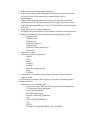
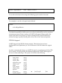
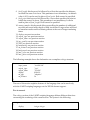
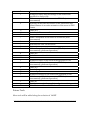
The following table summarizes the different technical features supported on the
different platforms targeted by YASRT:
Platform
Win32 Intel
FreeBSD Intel
Supported Features
Multi-threading
BMP, PPM, TGA, TIFF, JPEG & PNG
Native 3DS file support
3DS file converter and pre-viewer
Multi-threading
BMP, PPM, TGA, TIFF, JPEG & PNG
Native 3DS file support
3DS file converter and pre-viewer
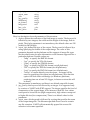
No Longer Supported
BeOS Intel
Multi-threading
Linux Intel
Comments
Primary target
Secondary target
FreeBSD can execute
Linux binaries
OpenGL bugs for pre-
AIX
BMP, PPM, TGA
Native 3DS file support
3DS file converter
Multi-threading
BMP, PPM, TGA, TIFF, JPEG & PNG
Multi-threading
BMP, PPM, TGA
BMP, PPM, TGA
DEC UNIX
BMP, PPM, TGA
HP-UX
BMP, PPM, TGA
Solaris
MacOS X
BMP, PPM, TGA
Multi-threading
BMP, PPM, TGA
BMP, PPM, TGA
Win32 Alpha
Irix
PocketPC
viewer: no longer
supported
Might not be supported
in the future
None
Might not be supported
in the future
Might not be supported
in the future
Might not be supported
in the future
None
None
Limited support
Future Features
The following list describes what will be implemented in future versions of
YASRT:
• Raytracing features:
1. Stochastic global illumination to take into account global illumination
effects (path tracing).
2. Use of photon tracing for advanced effects: global illumination (not to be
combined with path tracing) and caustics.
3. More camera models: orthographic and no parallax.
4. Area lights.
5. Support for procedural texturing.
6. Support for image mapping.
7. Layered fog.
8. New primitives:
- Blobs
- Height fields
• Technical features:
1. Support for direct output onto the screen for more platforms.
2. Support of any number of threads.
3. Enhanced scripting language.
4. Custom binary formats for easier and faster parsing and generation of
large scenes.
5. More auxiliary tools in the package (converters, plug-ins for commercial
3D packages, etc.).
6. GUI for easier manipulation and rendering.
Installation Notes
Windows
To install YASRT on Windows, please do the following:
1. Download YASRT from its official Web Site: http://www.yasrt.org.
2. Download the Windows version for your platform (Intel or Alpha).
3. Unzip the archive downloaded (by using WinZip for instance) into a
directory of your choice (e.g.: C:\YASRT).
4. Add the YASRT directory to your path environment variable:
- On the desktop, right-click on the My Computer icon.
- Select Properties.
- Select the Advanced tab (Windows 2000).
- Select Environment Variables…
- In the system variables section, double-click on PATH.
- Add YASRT directory (e.g.: C:\YASRT).
PocketPC
To install YASRT on the pocketPC platform, please do the following:
1. Download YASRT from its official Web Site: http://www.yasrt.org.
2. Download the pocketPC version for your platform (ARM only currently).
3. Unzip the archive downloaded (by using WinZip for instance) into a
directory of your choice (e.g.: /YASRT).
4. The program reads a scene file called scene.yst at the root directory.
5. Copy any scene to the root directory and rename it to scene.yst, then run
the program. The scene will be rendered directly onto the screen and
saved in the image file specified in the script. To start the rendering phase,
just tap on the screen.
Linux
To install YASRT on Linux, please do the following:
1. Download YASRT from its official Web Site: http://www.yasrt.org.
2. Download the Linux version for your platform (Intel only currently).
3. Uncompress the archive downloaded into a directory of your choice
(/usr/local/yasrt for example), by doing the following:
a. Open a Shell window
b. Create the installation directory, e.g.: mkdir /usr/local/yasrt
c. Copy the archive downloaded: cp yasrtXXXX.tgz /usr/local/yasrt
d. Change the local directory to that created, e.g.: cd /usr/local/yasrt
e. Uncompress the archive, e.g.: gunzip –d yasrtXXXX.tgz
f. Untar the archive, e.g.: tar –xvf yasrtXXXX.tar
4. Add the YASRT directory to your path environment variable:
DEC UNIX
See the Linux Installation Instructions for more details.
HP-UX
See the Linux Installation Instructions for more details.
AIX
See the Linux Installation Instructions for more details.
FreeBSD
See the Linux Installation Instructions for more details.
Solaris
See the Linux Installation Instructions for more details.
Irix
See the Linux Installation Instructions for more details.
BeOS
See the Linux Installation Instructions for more details.
MacOS X
See the Linux Installation Instructions for more details.
_______________________________________________________________________
Tutorial
This section is a tutorial that walks the user through the main features of YASRT.
This section is not meant to replace the full user’s reference section (see below),
but is just an introduction to the main features of the Raytracer.
YASRT language features
Environment
Camera
Lights
Textures
Primitives
[THIS SECTION: TO BE ADDED]
_______________________________________________________________________
YASRT Command-Line Options
YASRT is a command-line program (except for the pocketPC version which
features a simple user interface). This means that it must be started from a shell
or executed from an external program. This section describes all the commandline switches available to the program.
Note that the command-line options supersede the different directives given in
the scene description file given as input. This allows having a set of directives for
the final version of the scene, while still quickly allowing experimenting new
features with shorter rendering times (by overriding this set of directives).
Some command-line switches are available on some platforms only, while others
are common to all platforms. To quickly obtain a list of the different options
supported for a given platform, simply type yasrt in a shell window.
Input and Output File Options
This section describes the different command-line options that apply to input
and output files.
Input File
The scene to render is specified using the –i or --input switch followed by the
name of the input file. For example:
C:\YASRT\yasrt.exe –i myscene.yst (on Windows platforms)
Or
/yasrt –i myscene.yst (on UNIX platforms)
In this case, YASRT will try to parse the file called myscene.yst.
Note that this is the only required switch to render a particular scene. All other
switches override parameters describe in the settings section of the YASRT
scripting language (see below).
Output File
1. Output File Name
The output file name can be changed by using the –o or --output switch followed
by the name of the output file without any file extension. YASRT will
automatically append the correct file extension based on the output file type.
For example:
C:\YASRT\yasrt.exe –i myscene.yst –o mysenefirstrender (on Windows platforms)
Or
/yasrt –i myscene.yst –o mysenefirstrender (on UNIX platforms)
In this case the scene will be rendered to the myscenefirstrender image file. The
extension of this file depends on the output format specified in the settings
section of the script (the default being BMP).
2. Output File Type
The output file type can be changed by using the appropriate switch. Here is the
list of possible types:
- BMP: by using the –bmp or --bmp switch.
- TGA: by using the –tga or --tga switch.
- PPM: by using the –ppm or --ppm switch.
- PNG: by using the –png or --png switch (not supported on all
platforms).
- JPEG: by using the –jpg or --jpeg switch (not supported on all
platforms).
- TIFF: by using the –tif or --tiff switch (not supported on all
platforms).
- Screen output: by using the –screen or --screen switch (not
supported on all platforms).
For example:
C:\YASRT\yasrt.exe –i myscene.yst –o mysenefirstrender –ppm (on Windows
platforms)
Or
/yasrt –i myscene.yst –o mysenefirstrender –ppm (on UNIX platforms)
In this case the scene will be rendered to the myscenefirstrender.ppm image file.
Raytracing Options
This section describes the different command-line options that apply to
raytracing. It is possible for example to change the jittering and anti-aliasing
options through the use of command-line switches. Future versions will add
other features such as the possibility to adjust the quality of the rendering.
The anti-aliasing switches are the following ones:
1. For no anti-aliasing, use the –aan or --aanone.
2. For quick anti-aliasing, use the –aaq or --aaquick.
3. For adaptive anti-aliasing, use the –aaa or --aaadaptive followed by an integer
representing the threshold value used by this algorithm. Low values give best
results at the cost of the time spent to render the scene.
Jittering can be activated by using the –j or --jitter switch. Jittering introduce
random effects in the way rays are shot in the world. The effect is to reduce the
amount of aliasing in the final image.
To specify the size of the final image from the command-line, several switches
are available:
• -r or –resolution: this switch is followed by two positive integers
representing the width and height of the image to render.
• -w or –width: this switch is followed by a positive integer representing the
width of the image to render.
• -h or –height: this switch is followed by a positive integer representing the
height of the image to render.
For example:
C:\YASRT\yasrt.exe –i myscene.yst –aaa 24 (on Windows platforms)
Or
/yasrt –i myscene.yst –aaa 24 (on Unix platforms)
In this case the scene will be rendered using adaptive anti-aliasing with 24 as the
adaptive distance.
For more information on anti-aliasing and jittering, please refer to the
Environment section of the User’s Reference part of this document.
Advanced Options
This section describes the different advanced command-line options available.
Some of these options should be used with care as they change the way YASRT
works internally (the value of the priority queue size for instance).
Multi-Threading
Some versions of YASRT support multi-threading. Multi-threading is a technique
by which a program can execute several tasks in parallel. On machines with only
one processor, even though the program appears to be doing several things at
the same time, only one task is being executed at a given time. On machines with
more than one processor and depending on the underlying operating system, the
program will actually run its different tasks across the different processors
available. If the program is executing more tasks than the number of processors,
the different tasks will be shared among these processors. This sharing
mechanism is also known as time slicing (processor time is sliced and divided
among the different tasks to execute).
The multi-threaded version of YASRT uses threads to render the different parts
of an image in parallel. By default, the workload involved in rendering an image
is equally divided between the threads of execution. It is possible to increase that
number. YASRT can support two, four or eight threads of execution to speedup
rendering times. The default number of threads is 2.
To change the default number of threads, simply use the –t or the --thread switch
followed by 2, 4 or 8.
For example:
C:\YASRT\yasrtmt.exe –i myscene.yst –t 8 (on Windows platforms)
Or
/yasrtmt –i myscene.yst –t 8 (on Unix platforms)
In this case the scene will be rendered by eight parallel threads.
3DS File Support
On some platforms, YASRT supports the rendering of 3D Studio binary files
without needing the conversion of this type of files beforehand. In this case, two
additional switches are available: the -3ds or the –3ds switch followed by the
name of the YASRT configuration file (see next section), and the -c or the –-camera
switch followed by an integer representing which camera to use to render the
scene (3DS files can have several cameras defined).
For example:
C:\YASRT\yasrt.exe –3ds myscene.yst (on Windows platforms)
Or
/yasrt –3ds myscene.yst (on Unix platforms)
Priority Queue Size
YASRT uses a complex technique to avoid testing the intersection of every single
ray against every single primitive. When the number of primitives in the scene is
large (thousands of objects), the program might bail printing an error message
(YASRT is out of space... Please use the -pqs or --pqsize switch to increase the priority
queue size). In this case the priority queue size of the algorithm must be increased
(the default value is 128) by using the -pqs or the --pqsize switch followed by the
new value of the size of the priority queue.
For example:
C:\YASRT\yasrt.exe –i myscene.yst –pqs 170 (on Windows platforms)
Or
/yasrt –i myscene.yst –pqs 170 (on Unix platforms)
YASRT will use priority queues with a size of 170 elements maximum.
Note: it is highly recommended to leave the default value of this parameter.
This command-line switch should be used only when YASRT bails with the
error message corresponding to an insufficient priority queue size.
_______________________________________________________________________
Language Syntax
This section thoroughly describes the YASRT language used to describe 3d
scenes. This section is the core of the YASRT reference manual.
File types
This section describes the different types of files handled by YASRT.
Input files
YASRT reads textual files as input files for scene description files (ASCII files).
These files can be created using any text editor provided that they are saved as
ASCII files with no extra formatting. Example of text editors include:
- Notepad (Windows).
- WordPad (Windows, be sure to save the file as Text only).
- TexPad (Windows, http://www.textpad.com).
- vi (Unix platforms).
- Emacs (Unix and Windows platforms).
- Etc.
Future versions of YASRT will support binary files when image mapping is
supported. These binary files will be:
- PPM files (all platforms).
- BMP files (all platforms).
- TGA files (all platforms).
- JPEG files (depending on the platforms).
- TIFF files (depending on the platforms).
- PNG files (depending on the platforms).
On some platforms, YASRT also supports the rendering of 3D Studio binary files
without needing the conversion of this type of files beforehand. An ASCII file
needs to be created in order to tell YASRT how to render the scene. The content
of that file is described in the corresponding section below.
Output files
YASRT supports binary files to output the images created. The formats
supported are:
- PPM files (all platforms) – 24-bit (16M colors) – uncompressed.
- BMP files (all platforms) – 24-bit (16M colors) – uncompressed.
- TGA files (all platforms) – 24-bit (16M colors) – uncompressed.
- JPEG files (platform-dependant) – 24-bit (16M colors) –
compressed.
- TIFF files (platform-dependant) – 24-bit (16M colors) – compressed.
- PNG files (platform-dependant) – 24-bit (16M colors) – compressed.
File inclusions
It is possible to include files within YASRT scene description files by using the
include directive. This feature allows artists to create libraries of objects or
libraries of colors, for example. What follows is an example of inclusion inside a
script:
include “mycolors.inc”
include “myobjects.inc”
….
The mycolors.inc and myobjects.inc files are valid ASCII files containing YASRT
objects, color declarations and so forth.
Data types
Before describing all the primitives supported by YASRT, it is important to
present the different types of data that are manipulated by the raytracer.
YASRT supports different types of entities. This section describes these entities
and gives examples on how to use them. These will serve as the basis for
primitive declarations.
Integers
Integers are used by YASRT to determine integer numbers. Integer values can be
positive, negative or null, depending on the context in which they are used. What
follows is an example of the use of an integer in a YASRT script:
settings
{
display 800 600
…
This example shows how to define the output format of the image to render. The
first integer represents the width of the image; the second integer represents the
height of this image (see below for more details).
Floats
Floats are used by YASRT to determine floating-point numbers. Float values can
be positive, negative or null, depending on the context in which they are used.
What follows is an example of the use of a float in a YASRT script:
settings
{
haze_factor 0.345
…
This example shows how to define the contribution of haze in a scene (see below
for more details).
Colors
YASRT makes extensive uses of colors in many of its structures. A color is
defined by three floating-point components representing (in order of
appearance): the red component, the blue component and the green component.
What follows is an example of the use of a color in a YASRT script:
settings
{
background 0.078 0.361 0.753
…
In this example, the background color of the image will have a red component of
0.078, a green component of 0.361 and a blue component of 0.753. Note that for
‘normal’ colors, the components lie between 0.0 and 1.0. When all components
are null (0.0), the color specified is black; when they are all equal to 1.0, the color
specified is white; additionally, when the components are all equal, the color
specified is a shade of grey. Color components can be greater than 1.0 in the case
of lights. As a matter of fact, as we will see later, light can fade proportionally
with distance (like in the real world), if the color specified in the color structure is
not sufficient (in this case the color of the light represents the intensity of the
light), the scene won’t be lit properly. For more details about this effect, see
below.
Another way to use colors is by declaring them, as shown in the following
example:
declare "AigueMarine"
…
color .498039 1 .831373
This example shows how to declare a color called "AigueMarine" for later use in
the script (the color can also be part of an include file as described before). For
more details on the declare directive, see below.
Vectors
YASRT makes extensive uses of vectors in many of its structures. A vector is
defined by three floating-point components representing (in order of
appearance): the ‘x’ component, the ‘y’ component and the ‘z’ component. What
follows is an example of the use of a vector in a YASRT script:
plane
{
normal <0 0 1>
distance -0.5
}
…
This example shows how to declare a plane. The ‘normal’ vector represents the
normal of the plane (for more details on the plane structure, see below).
Strings
YASRT uses strings in different elements of its scripting languages, generally
textual directives. Strings are enclosed between double quotes (“). What follows
is an example of the use of a string in a YASRT script:
settings
{
output_type "bmp"
…
This example shows how to specify the BMP file format for the output image. For
more details on the output_type directive, see below.
Variable declarations
To easily re-use different elements of the YASRT language within the same scene
or to share these elements between different scenes, it is possible to declare
elements (colors, floats, integer values, primitives, textures, etc.).
NOTE: the current version of YASRT only supports declaration for colors. Future
versions of YASRT will support declarations for other elements of the language
(integers, doubles, strings, surfaces, primitives, etc.).
The declare keyword is used for that purpose. The syntax of this keyword is as
follows:
declare string data_type_name data_type_definition
In the current version of YASRT, data_type_name can only be “color”.
data_type_definition is therefore a color definition. For example, to declare a color
and associate the name AigueMarine to it, use the following:
declare "AigueMarine"
…
color .498039 1 .831373
To use this color later in the script, the following syntax needs to be used:
#color_name
For example, to use the color previously defined:
surface
{
color #AigueMarine
…
It is therefore possible to define your own colors in include files, and re-use them
in numerous scenes. Future versions of YASRT will support library paths: this
feature will allow the raytracer to look for include files in specific directories
without having to specify the full path to those files in the scenes using them.
3DS File Support
YASRT supports the 3DS file format natively. This feature has not been
implemented on all platforms yet. Not all features of the file format are support
either.
In order to activate this feature, an ASCII file must be created along with the 3DS
file to render. This file specifies the different options that YASRT must apply to
the scene when rendering it. The syntax of this file is the following:
{
input_name
output_type
output_name
attenuation_type
shadow_type
radius
light_samples
camera_index
aperture
focal_point
camera_samples
string
string
string
string
string
double
integer
integer
double
vector
integer
or
focal_length
float
background
display
jpeg_quality
jitter
antialiasing
aa_distance
haze_color
haze_factor
color
integer integer
integer
string
string
integer
color
float
}
Note that this file contains only one section enclosed in curly brackets.
Everything else in the file will be either ignored, or cause a parsing error.
Here is a description for each parameter of this structure:
1. input_name: this keyword is followed by a string that specifies the name of
the input 3DS file. The filename has to contain the “.3ds” extension.
2. attenuation_type: this keyword is common to all light sources present in the
3DS scene. It allows specifying which light attenuation model to use
during rendering. Possible values are:
- none: no light attenuation will be used.
- d: the attenuation will be proportional to the inverse of the distance
from the light.
- d2: the attenuation will be proportional to the inverse of the square
of the distance from the light.
3. shadow_type: this keyword is common to all light sources present in the
3DS scene. It allows specifying which type of shadow to use during
rendering. Possible values are:
- sharp: the shadows cast in the scene will be sharp.
- smooth: the shadows cast in the scene will be smooth. This effect is
also referred to as penumbra. The output results are more realistic
at the cost of longer rendering times.
4. radius: this keyword specifies the smoothness of the smooth shadows of
the scene. Larger values lead to smoother shadows. The next keyword
must be then used in order to avoid aliasing effects.
5. light_samples: this keyword specifies the number of additional rays to trace
when smooth shadows are activated. Larger values lead to smoother
shadows and less aliasing effects at the cost of longer rendering times.
6. camera_index: the 3DS file format support multiple cameras in the scene. In
order to use one given camera in the scene, this keyword can be used.
7. aperture: this keyword allows activating the depth of field effect. The effect
can be amplified by using large values, at the cost of rendering effects.
8. focal_length: this keyword is followed by a float that specifies the distance
at which the scene is in focus. This parameter is not mandatory, its default
value is 10. It can be used in place of focal_point. Both cannot be specified.
9. focal_point: this keyword is followed by a vector that specifies the point at
which the scene is in focus. This parameter is not mandatory. It can be
used in place of focal_length. Both cannot be specified.
10. camera_samples: this keyword allows controlling the number of additional
rays that are traced when depth of field is activated. Large values will lead
to smoother results and less aliasing effects at the cost of longer rendering
times.
11. display: see previous section.
12. output_type: see previous section.
13. output_name: see previous section.
14. jpeg_quality: see previous section.
15. jitter: see previous section.
16. antialiasing: see previous section.
17. aa_distance: see previous section.
18. background: see previous section.
19. haze_color: see previous section.
20. haze_factor: see previous section.
The following example shows the declaration on a complete settings structure:
{
input_name
output_type
output_name
display
aa_type
aa_distance
"test3ds.3ds"
"tga"
"test3ds"
800 600
"adaptive"
16
}
The rest of this section explains features of the language that can be used only
with the YASRT scripting language, not the 3DS file format support.
Environment
The settings section of the YASRT scripting language defines different directives
concerning the rendering of the current scene. The syntax is the following:
settings
{
display
integer integer
output_type
output_name
jitter
jpeg_quality
antialiasing
aa_distance
background
haze_color
haze_factor
string
string
string
integer
string
integer
color
color
float
}
Here is a description for each parameter of this structure:
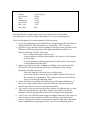
1. display: defines the resolution of the final image to render. The keyword is
followed by two integers, the width and the height of the image, both in
pixels. The display parameter is not mandatory; the default values are 320
(width) by 240 (height).
2. output_type: defines the type of the output. The keyword is followed by a
string specifying the format of the output image. The value of this
parameter depends on the platform and the support of image file types.
See the release notes for more information on the formats supported for a
particular platform. Possible values are:
- “bmp”: to specify the BMP file format.
- “tga”: to specify the TGA file format.
- “ppm”: to specify the PPM file format.
- “jpeg”: to specify the JPEG file format (not all platforms).
- “tiff”: to specify the TIFF file format (not all platforms).
- “png”: to specify the PNG file format (not all platforms).
- “screen”: to render directly onto the screen – no image will be
saved by specifying this option (not all platforms). Note that this
option will slow down renderings (on Windows platforms,
rendering time are at least 50% bigger, in future versions this will
be fixed).
This parameter is mandatory and there is no default output file format.
3. jpeg_quality: this keyword is followed by an integer. It is supported only
by versions of YASRT with JPEG support. The integer specifies the level of
compression of the output image, it lies between 0 and 100. Low values
correspond to lower file size (high compression), high values correspond
to higher file size (low compression). There is no default value for this
parameter.
4. output_name: this keyword is followed by a string that specifies the name
of the output image file. The filename specified doesn’t need to contain
any file extension. YASRT will automatically append the correct file
extension to the name specified.
5. jitter: this keyword is followed by a string specifying if jittering should be
used during the rendering of the output image. Its value can be either ‘yes’
or ‘no’. This parameter is not mandatory, and by default jittering is not
activated. Jittering allows YASRT to introduce pseudo-random values
when tracing rays. This feature is useful because it helps reducing the
appearance of aliasing effects (see below) to the human brain. However,
jittering shouldn’t be used when generating the successive frames of an
animation. Since pseudo-random values are used when tracing rays,
undesired visual effects are generated (noise) when objects moved during
animation.
6. antialiasing: this keyword is followed a string specifying the type of antialiasing to use during rendering. The different values can be:
- ‘none’: no anti-aliasing is used. This leads to the fastest renderings,
at the cost of a poor quality in the results obtained. This technique
should be used in intermediate renderings only.
- ‘quick’: a quick anti-aliasing technique is used. This provides a good
trade-off between rendering times and rendering qualities, and is
slower than with no anti-aliasing. This technique should be used in
intermediate renderings only.
- ‘adaptive’: an adaptive anti-aliasing technique is used. Put simple,
this complex technique recursively sub-divides each pixel and
traces new rays until a threshold is reached (see below). As a result
far more rays are traced than in any of the previous techniques
presented. Calculation times are therefore tremendously increased;
this is why this technique should be used for final renderings.
The default value for this parameter is ‘none’ (no anti-aliasing by default).
7. aa_distance: this keyword is followed by an integer that specifies the
threshold value used when adaptive anti-aliasing is activated. Low values
give the best results as more rays are traced; this therefore leads to longer
rendering times. High values give good results with faster rendering
times, at the cost of a poor quality in the final image. This parameter is not
mandatory and its default value is 64.
8. background: this keyword is followed by a color that specifies the
background color of the image. If a ray that is traced into the virtual world
doesn’t hit any primitive present, the color returned is that specified by
this parameter. This parameter is not mandatory, and its default value is
black (0 0 0).
9. haze_color: YASRT can simulate haze effects. This parameter is followed by
a color specifying of the haze when this effect is activated. This parameter
is not mandatory, and its default value is black (0 0 0).
10. haze_factor: this parameter is followed by a float value that specifies the
importance of the haze effect in the scene. High values lead to thick haze.
A value of 0 means that the haze effect is not activated. This parameter is
not mandatory, and its default value is 0.
The following example shows the declaration on a complete settings structure:
settings
{
display
output_type
output_name
jitter
jpeg_quality
antialiasing
aa_distance
background
haze_color
haze_factor
}
1024 768
“jpeg”
“myScene”
“no”
90
“adaptive”
32
<0 0 0>
<1 1 1>
0.05
Camera
The camera section of the YASRT scripting language defines the different
parameters of the camera of the scene. The syntax is the following:
camera
{
position
look_at
up
projection_type
fov
ratio
aperture
focal_point
camera_samples
vector
vector
vector
string
float
float
float
vector
integer
or
or
focal_length
samples
float
integer
}
Here is a description for each parameter of this structure:
1. position: this keyword is followed by a vector that specifies the position of
the viewer. This parameter is mandatory and there is no default value.
2. look_at: this keyword is followed by a vector that specifies where the
viewer is looking at in the virtual world. This parameter is mandatory and
there is no default value.
3. up: this keyword is followed by a vector that defines what vector should
be considered as the altitude. For left-handed systems, the value is <0 1
0>, for right-handed systems, it is <0 0 1>. This parameter is not
mandatory, its default value is <0 0 1> (YASRT is right-handed by
default).
4. projection_type: this keyword is followed by a string that specifies the type
of projection to use. Possible values are:
- flat: standard 3d projection will be used.
- fisheye: a fisheye projection will be used.
5. fov: this keyword is followed by a float that specifies the field of view in
degrees. Small values will lead to an effect of zooming in (close up), while
large values will lead to an effect of zooming out. This parameter is not
mandatory; its default value is 45.
6. ratio: this keyword is followed by a float that specifies the ratio of the final
image to render. Normal computer screens have a ratio of 4/3. Standard
resolutions also use this ratio (640x480, 1024x768, etc.). This parameter is
not mandatory, its default value is 4/3.
7. aperture: this keyword is followed by a float that specifies the importance
of the effect of depth of field. This effect simulates that seen in real
photographs where objects out of focus will appear blurry. Large values
will lead to accentuating this effect. This parameter is not mandatory, its
default value is 0.0 (no depth-of-field effect by default).
8. focal_length: this keyword is followed by a float that specifies the distance
at which the scene is in focus. This parameter is not mandatory, its default
value is 10. It can be used in place of focal_point. Both cannot be specified.
9. focal_point: this keyword is followed by a vector that specifies the point at
which the scene is in focus. This parameter is not mandatory. It can be
used in place of focal_length. Both cannot be specified.
10. camera_samples: this keyword is followed by an integer that specifies the
number of extra rays to trace when depth of field is activated. Large
values will slow rendering times but lead to better visual results. This
parameter is not mandatory, its default value is 16.
11. samples: this keyword is the same as camera_samples.
The following example shows the declaration of a camera:
camera
{
position
look_at
up
fov
ratio
<10 10 10>
<0 0 0>
<0 0 1>
60
1.33333
aperture
focal_length
samples
0.15
11
16
}
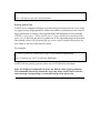
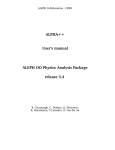
Here is an example of a scene using the depth of field effect:
The following example shows a scene using the fisheye projection:
Lights
The light section of the YASRT scripting language defines the different
parameters of the lights of the scene. The syntax is the following:
light
{
position
target
color
attenuation_type
shadow_type
radius
min_angle
max_angle
light_samples
vector
vector
color
string
string
double
double
double
integer
or
samples
}
Here is a description for each parameter of this structure:
integer
1. position: this keyword is followed by a vector that specifies the position of
the light. This parameter is mandatory and there is no default value.
2. color: this keyword is followed by a color that specifies the color of the
light. Currently YASRT supports the effect of fading of intensity: the
intensity of a light source decreases with the distance from the center of
the light source. In this case, the color can be thought of as the intensity of
the light. Since, this parameter depends on the overall scale of the scene, it
needs to be carefully adjusted, and as a result, the color of a light can have
its components greater than 1.0. This parameter is mandatory and there is
no default value.
3. attenuation_type: this keyword allows specifying which light attenuation
model to use during rendering. Possible values are:
• none: no light attenuation will be used.
• d: the attenuation will be proportional to the inverse of the distance
from the light.
• d2: the attenuation will be proportional to the inverse of the square of
the distance from the light. This is the default value if the keyword is
not present in the light declaration.
4. shadow_type: this keyword allows specifying which type of shadow to use
during rendering. Possible values are:
• sharp: the shadows cast in the scene will be sharp.
• smooth: the shadows cast in the scene will be smooth. This effect is also
referred to as penumbra. The output results are more realistic at the
cost of longer rendering times.
5. radius: this keyword specifies the smoothness of the smooth shadows of
the scene. Larger values lead to smoother shadows. The next keyword
must be then used in order to avoid aliasing effects.
6. light_samples or samples: this keyword specifies the number of additional
rays to trace when smooth shadows are activated. Larger values lead to
smoother shadows and less aliasing effects at the cost of longer rendering
times.
7. target: this keyword is used to specify the target point of a spot light.
8. min_angle: this keyword is used to specify the angle of the spot light under
which the scene is fully lit. Its value must be lower than that of the
max_angle parameter (see below).
9. max_angle: this keyword is used to specify the angle of the spot light under
which the light diminishes. A point in the scene at an angle greater than
this value will not be lit by the corresponding spot light.
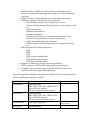
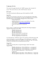
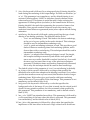
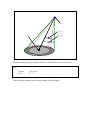
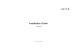
The following diagram illustrates the different parameters of a spot light:
position
min_angle
target
max_angle
The following example is a light located at <10 10 10> and of a white color:
light
{
position
color
<10 10 10>
111
}
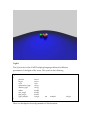
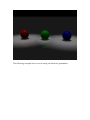
The following example shows a scene using two spot lights:
The following example shows a scene using soft shadows (penumbra):
Textures
The surface section of the YASRT scripting language defines the different
parameters of the surface of an object. Currently, YASRT only supports some
texturing features like: reflection, refraction and specular reflection. Future
versions will support more advanced texturing models (procedural texturing,
including: texture mapping, bump mapping, etc.).
Once a texture is declared in a script it is applied to all the objects that follow in
the script. To change a texture, simply declare a new one, it will be used by all
following objects within the script.
The syntax is the following:
surface
{
color
ambient
diffuse
brilliance
color
float
float
float
specular
roughness
reflection
reflection_type
reflection_radius
reflection_samples
refraction
refraction_index
float
float
float
string
float
integer
float
float
}
Here is a description for each parameter of this structure:
1. color: this keyword is followed by a color that specifies the intrinsic
color of the object. This color will be used by the raytracing engine
along with the following parameters in the structure to determine the
exact color at a point on the surface of an object.
2. ambient: this keyword is followed by a float that specifies the ambient
factor of the object. The ambient term in raytracing is used to simulate
the effect of global illumination in a scene. Since standard raytracing
cannot determine the exact value of this term, it is simulated by using a
constant value. The value can range from 0.0 to 1.0. Typical values
range from 0.1 to 0.3. Large value will render the object glowing.
3. diffuse: this keyword is followed by a float that specifies the amount of
light that is reflected off the surface at the exact same angle it came in.
This term is also known as diffuse reflection. A value of 0.5 means for
example that 50% of the light seen from the object comes directly from
the different light sources of the scene. The rest is absorbed by the
object.
4. brilliance: this keyword is followed by a float that controls the way light
interacts with the object depending on the incident angle. High values
will make the object look more metallic.
5. specular: this keyword is followed by a float that controls the way
highlights are generated when the light bounces off the object’s
surface. Simply put, highlights are the bright spots that appear on
objects that depend upon viewing angle and illumination angle. The
specular term can range from 0.0 to 1.0, 0.0 meaning no highlights,
while 1.0 means total saturation of the highlight.
6. roughness: this keyword is followed by a float that controls the size of
the highlight. Large values will give large highlights, while small
values will give very smooth and small highlight.
7. reflection: this keyword is followed by a float that controls the amount
of light that is reflected off the surface of the object. The value can
range from 0.0 (no reflection) to 1.0 (total reflection). The light is
reflected off the surface with the same angle as the incident light. Note
that reflection increases rendering times since new rays must be traced
from the intersection point on the surface.
8. reflection_type: this parameter can be either sharp or fuzzy. sharp will use
sharp reflections for the current surface (standard model), whereas
fuzzy will activate fuzzy reflection. In this case the two following
keywords must be specified.
9. reflection_radius: this parameter specifies how fuzzy the reflections can
be. Large values will lead to more fuzzy reflections at the cost of more
aliasing effects. In order to smooth the appearance of very fuzzy
reflections, the following parameter must be adjusted.
10. reflection_samples: this parameter controls the number of ray samples
that are reflected for each incoming ray. The larger the value, the better
the results, at the cost of longer rendering times. Note that this
parameter must be set according to the value of the previous
parameter.
11. refraction: this keyword is followed by a float that controls the amount
of light that is refracted by the surface. The value can range from 0.0 to
1.0. It can be thought of as the transparency of the object to which it is
applied. Note that refraction increases rendering times since new rays
must be traced from the intersection point on the surface. The default
value is 0.0 (no refraction).
12. refraction_index: this keyword is followed by a float that specifies the
index of refraction of the object. Typical values are: 1.0 for air, 1.33 for
water, 1.5 for glass and 2.4 for diamond. The default value is 1.0 (air).
What follows is the example of simple surface declaration:
surface
{
color
ambient
diffuse
brilliance
specular
roughness
reflection
refraction
refraction_index
0.419 0.556 0.137
0.1
0.75
1.0
0.3
10.0
0.25
0.0
1.0
}
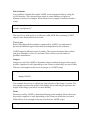
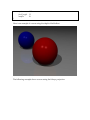
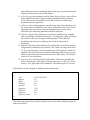
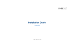
The following picture shows (the Cornell room) a scene where different types of
surfaces are used:
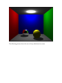
The following picture shows the use of fuzzy reflections in a scene:
Primitives
This section describes the different primitives supported by YASRT.
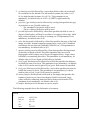
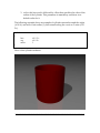
Sphere
The sphere is the fastest and simplest object to render with a raytracing program.
The syntax is a follows:
sphere
{
center
radius
vector
float
}
Here is a description for each parameter of this structure:
1. center: this keyword is followed by a vector that specifies the center of
the sphere. This parameter is mandatory and there is no default value
for it.
2. radius: this keyword is followed by a float that specifies the value of the
radius of the sphere. This parameter is mandatory and there is no
default value for it.
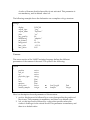
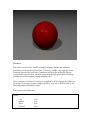
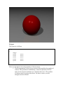
The following example shows of sphere centered around the origin (<0 0 0>) and
with a unit radius (1):
sphere
{
center
radius
<0 0 0>
1
}
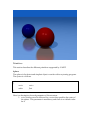
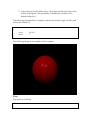
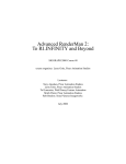
The following image is an example of such a sphere:
Plane
The syntax is a follows:
plane
{
normal
distance
vector
float
}
Here is a description for each parameter of this structure:
1. normal: this keyword is followed by a vector that specifies the normal
of the plane. This parameter is mandatory and there is no default value
for it.
2. distance: this keyword is followed by a float that specifies the value of
the distance of the plane from the origin. This parameter is mandatory
and there is no default value for it.
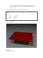
The following example shows the declaration of the (x, y) plane at one unit down
on the z axis (i.e.: which equation is z=-1):
plane
{
normal
distance
<0 0 1>
-1
}
By adding this declaration to the previous scene, the plane is added to the scene:
Polygon
The syntax is a follows:
polygon
{
integer
vertex
vertex
vertex
vertex
vertex
…
}
vector
vector
vector
vector
vector
Here is a description for each parameter of this structure:
1. The first parameter of the polygon structure that specifies the number of
vertices. This parameter is mandatory, it must be placed as the first
entry of the structure and there is no default value for it. The number
of vertices must be greater than three. For three vertices, use the
triangle structure instead.
2. vertex: this keyword is followed by a vector that specifies one the
vertices of the polygon. The vertices must be declared in the counter
clockwise order.
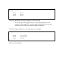
The following example shows the declaration of a polygon:
polygon
{
4
vertex
vertex
vertex
vertex
}
<-1.5 -1.5 0>
<1.5 -1.5 0>
<2 2 0>
<-2 2 0>
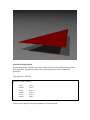
Here is such a polygon:
Triangle
The syntax is a follows:
triangle
{
vertex
vertex
vertex
}
vector
vector
vector
Here is a description for each parameter of this structure:
1. vertex: this keyword is followed by a vector that specifies one the
vertices of the triangle. The vertices must be declared in the counter
clockwise order. Only three vertices must be declared.
The following example shows the declaration of a triangle:
triangle
{
vertex
vertex
vertex
}
<-1.5 -1.5 0>
<1.5 -1.5 0>
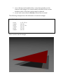
<2 2 0>
Here is such a triangle:
Smooth triangle (patch)
A smooth triangle contains not only vertices, but also the normal at each vertex.
This primitive is primarily used when exporting scenes from commercial
packages.
The syntax is a follows:
patch or smooth_triangle
{
vertex
vector
normal
vector
vertex
vector
normal
vector
vertex
vector
normal
vector
}
Here is a description for each parameter of this structure:
1. vertex: this keyword is followed by a vector that specifies one the
vertices of the triangle. The vertices must be declared in the counter
clockwise order. Only three vertices must be declared.
2. normal: each vertex must be directly followed by its normal.
The following example shows the declaration of a smooth triangle:
smooth_triangle
{
vertex
normal
vertex
normal
vertex
normal
}
<-1.5 -1.5 0>
<0 0 1>
<1.5 -1.5 0>
<0 0 1>
<2 2 0>
<0 0 1>
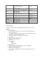
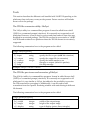
Here is such a smooth triangle:
The following picture shows the use of a large amount of smooth triangles in a
scene (3DS file courtesy of Ludovic Bridant):
Ring
The syntax is a follows:
ring
{
center
normal
internal_radius
external_radius
vector
vector
float
float
}
Here is a description for each parameter of this structure:
1. center: this keyword is followed by a vector that specifies the center of
the ring. This parameter is mandatory and there is no default value for
it.
2. normal: this keyword is followed by a vector that specifies the normal
of the ring. This parameter is mandatory and there is no default value
for it.
3. internal_radius: this keyword is followed by a float that specifies the
value of the internal radius. This parameter is mandatory and there is
no default value for it.
4. external_radius: this keyword is followed by a float that specifies the
value of the external radius. This parameter is mandatory and there is
no default value for it.
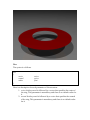
The following example shows the declaration of a ring:
ring
{
center
normal
internal_radius
external_radius
}
Here is this ring rendered:
<0 0 0>
<0 0 1>
1
2
Disc
The syntax is a follows:
disc
{
center
normal
radius
vector
vector
float
}
Here is a description for each parameter of this structure:
1. center: this keyword is followed by a vector that specifies the center of
the ring. This parameter is mandatory and there is no default value for
it.
2. normal: this keyword is followed by a vector that specifies the normal
of the ring. This parameter is mandatory and there is no default value
for it.
3. radius: this keyword is followed by a float that specifies the value of the
radius. This parameter is mandatory and there is no default value for
it.
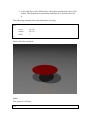
The following example shows the declaration of a ring:
disc
{
center
normal
radius
<0 0 0>
<0 0 1>
1
}
Here is this disc rendered:
Cone
The syntax is a follows:
cone
{
base
cap
base_radius
cap_radius
vector
vector
float
float
}
Here is a description for each parameter of this structure:
1. base: this keyword is followed by a vector that specifies the base of the
cone. This parameter is mandatory and there is no default value for it.
2. base_radius: this keyword is followed by a float that specifies the value
of the radius of the cone at the base. This parameter is mandatory and
there is no default value for it.
3. cap: this keyword is followed by a vector that specifies the cap of the
cone. This parameter is mandatory and there is no default value for it.
4. cap_radius: this keyword is followed by a float that specifies the value
of the radius of the cone at the cap. This parameter is mandatory and
there is no default value for it.
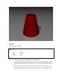
The following example shows an example of cone centered around the origin (<0
0 0>) and with a unit radius (1), that extends along the z axis on 5 units (<0 0 5>),
and has a radius of 0.5 at the cap:
cone
{
base
cap
base_radius
cap_radius
<0 0 -1>
<0 0 1>
1
0.5
}
Here is this cone rendered:
Cylinder
The syntax is a follows:
cylinder
{
base
cap
radius
}
vector
vector
float
Here is a description for each parameter of this structure:
1. base: this keyword is followed by a vector that specifies the base of the
cylinder. This parameter is mandatory and there is no default value for
it.
2. cap: this keyword is followed by a vector that specifies the cap of the
cylinder. This parameter is mandatory and there is no default value for
it.
3. radius: this keyword is followed by a float that specifies the value of the
radius of the cylinder. This parameter is mandatory and there is no
default value for it.
The following example shows an example of cylinder centered around the origin
(<0 0 0>) and with a unit radius (1), that extends along the z axis on 5 units (<0 0
5>):
cylinder
{
base
cap
radius
}
<0 0 -1>
<0 0 1>
1
Here is this cylinder rendered:
_______________________________________________________________________
Tools
This section describes the different tools bundled with YASRT. Depending on the
platforms, these tools may or may not be present. Future versions will include
more tools in the package.
The 3DS file conversion utility: 3ds2yst
The 3ds2yst utility is a command-line program. It must be called from a shell
(UNIX) or a command-prompt (windows). It is currently not supported on all
platforms. However, it can be used to convert and then render a scene that was
modeled in an external package. The 3DS file can then be converted to a YASRT
ASCII file and rendered on a platform where the 3DS file format is not natively
supported.
The following summarizes how to the program can be called:
Usage: 3ds2yst [options]
Options:
-i/--input
string
specify the file to open (with 3ds extension)
-o/--output
string
specify the output file (no extension)
-c/--camera
integer
specify the initial camera to use
-t/--triangle
triangles as output (default is patches)
-?/--help
this help message
Example: 3ds2yst -i car.3ds -o cartest
The 3DS file pre-viewer and converter: gl3ds2yst
The gl3ds2yst utility is a command-line program. It must be called from a shell
(UNIX) or a command-prompt (windows). It is currently not supported on all
platforms. It is very similar to 3ds2yst, but adds also the possibility to preview
the 3DS scene before converting it. Additionally, it can be used to take
screenshots from the OpenGL rendering window with anti-aliasing in different
file formats.
The following summarizes how to the program can be called:
Usage: gl3ds2yst [options]
Options:
-w/--width
integer
-h/--height
integer
-d/--display
string
width of the output image
height of the output image
type of display (points, lines, triangles)
-o/--output
string
YASRT file to export to (no extension)
-c/--camera
integer
the initial camera to use
-i/--input
string
file to open (with extension)
-l/--light
load lights in OpenGL (experimental)
-t/--triangle
triangles as input (default is patches)
-x/--texture
load textures in OpenGL (experimental)
-?/--help
this help message
Example: gl3ds2yst -i car.3ds -o cartest
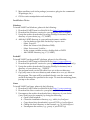
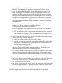
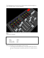
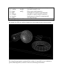
By default, the 3D view will be displayed in wire-frame mode as shown below:
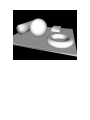
By using the appropriate command-line switch, it is possible to use a shaded or
point rendering mode, as shown in the two following screenshots:
It is possible to interact with the keyboard and mouse. By left-clicking and
moving the mouse (while keep the left button pressed), it is possible to look
around in the 3D world of the scene. The right button of the mouse activates or
de-activates the automatic animation of the scene (rotation around the target
point of the camera).
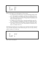
The keyboard interactions are summarized below:
Key
Description
>
<
-
Go to the next camera in the 3DS file
Go to the previous camera in the 3DS file
Enlarge the camera field of view, thus giving the
impression of zooming out
Reduce the camera field of view, thus giving the impression
of zooming in
Activate/de-activate the animation of the scene (rotation
around the target point of the camera)
Same as a
Make a screenshot of the screen to a BMP file (autoincremented)
+
a
A
b
B
c
C
d
D
f
F
i
I
j
J
k
K
n
N
o
p
P
q
Q
s
t
T
y
Y
Same as b
Dump the objects and the settings of the scene in the
specified inc and yst file.
Make a screenshot of the screen to a TGA file (autoincremented)
Activate/de-activate the creation of the successive antialiased frames of an entire animation of the scene in PNG
format
Same as d
Switch to full screen mode
Same as f
Make a screenshot of the screen to a PPM file (autoincremented)
Same as i
Anti-alias the view on the screen
Same as j
Make a screenshot of the screen to a JPG file (autoincremented) (platform-dependent)
Same as k
Switch to normal resolution
Same as n
Dump the objects of the scene in the specified inc file.
Make a screenshot of the screen to a PNG file (autoincremented) (platform-dependent)
Same as p
Exit the program
Same as q
Dump the settings of the scene in the specified yst file.
Make a screenshot of the screen to a TIFF file (autoincremented) (platform-dependent)
Same as t
Cycle between wire-frame, plain and point rendering mode
Switch between flat and shaded model
Future Tools
More tools will be added along the evolution of YASRT.
_______________________________________________________________________