1
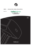
Installation and Operation Manual
Room Air Conditioners
Z Series Inverter Range Split Type
DC Inverter
ECO1850SD
Register your air conditioner
Model information can be found on the CE
label.
Please register your product online at
www.ecoair.org. For your future
convenience, record the model information
below.
____________________________________
MODEL NUMBER
____________________________________
SERIAL NUMBER
____________________________________
PURCHASE DATE
What’s in the box
1 x Z Series Indoor Unit
1 x Z Series Outdoor Unit
1 x Remote Control
1 x Drain Hose
1 x User Manual
1 x Hole Cover Plate
1 x Drain Joint
4 x Wall Plugs and Screws.
1 set of Copper Pipes
This appliance can be used by minors from 8 years and above and persons with reduced physical,
sensory or mental capabilities or lack of experience and knowledge if they have been given supervision
or instruction concerning use of the appliance in a safe way and understand the hazards involved.
Children should not play with the appliance. Cleaning and user maintenance shall not b e made
by minors without supervision.
WEE/EC2601UR
This marking indicates that this product should not be disposed with other household waste
throughout the EU. To prevent possible harm to the environment or human health from
uncontrolled waste disposal, recycle it responsibly to promote the sustainable reuse of
material resources
.
or return your used device, please use the return and collection systems
or contact the retailer where the product was purchased. They can take this product for
environmental safe recycling.
R410A(R32/125: 50/50): 1975
Content
BS Plug Wiring ...................................................................................................... 1
Operation Notices
Precautions ........................................................................................................... 2
Part Names ........................................................................................................... 3
Screen Operation GuideScreen Operation Guide
Buttons on the remote control ............................................................................... 4
Introduction to buttons on the display screen ........................................................ 4
Introduction for buttons on the remote control ...................................................... 5
Function introduction for combination buttons ...................................................... 8
Operation
Operation guide .................................................................................................... 9
Replacement of batteries in remote control .......................................................... 9
Emergency operation ...........................................................................................10
Clean and Maintenance ....................................................................................... 10
Malfunction
Malfunction analysis .............................................................................................13
Installation Notice
Installation dimension diagram ............................................................................ 17
Tools for installation .............................................................................................18
Selection of installation location ...........................................................................18
Requirements for electric connection ...................................................................19
Installation
Instalation of indoor unit .......................................................................................20
Installation of outdoor unit ....................................................................................25
Vaccum pumping ................................................................................................. 28
Leakage detection ................................................................................................28
Post Installation checklist .....................................................................................29
Test and Operation
Test and operation ............................................................................................... 29
Attachment
Configuration of connection pipe ......................................................................... 30
Pipe expanding method ...................................................................................... 32
BS Plug Wiring
Wiring Instructions: Should it be necessary to change the plug please
note the wires in the mains lead are coloured in accordance with the
following code:
BLUE - NEUTRAL
BROWN – LIVE
GREEN AND YELLOW - EARTH
As the colours of the wires in the mains lead of this appliance may not
correspond with the coloured markings identifying the terminals in your plug,
proceed as follows:
1. The BLUE wire is the NEUTRAL and must be connected to the terminal
which is marked with the letter N or coloured BLACK.
2. The BROWN wire is the LIVE and must be connected to the terminal which
is marked with the letter L or coloured RED.
3. The GREEN/YELLOW is the EARTH and must be connected to the
terminal which is marked with the letter E or
or coloured GREEN or
GREEN/YELLOW.
4. Always ensure that the cord grip is positioned and fastened correctly.
If a 13 Amp (BS 1363) fused plug is used it must be fitted with a 13 Amp fuse.
If in doubt consult a qualified electrician. (For 9000BTU and 12000BTU unit only.)
(For 18000BTU use 20 Amp (fuse) supply from the main.)
Wiring for a 13 Amp Plug (BS1363)
Please note. The Earth Terminal is marked with the letter E or
Earth (Green / Yellow)
13 AMP
Neutral - N
(Blue)
Live - L
(Brown)
1
Earth Symbol.
PRECAUTIONS
WDUQLQJ
Ɣ'RQRWFRQQHFWWKHDLUFRQGLWLRQHUWRDFRQYHUVLRQRUH[WHQVLRQVRFNHWDVWKLV
PD\FDXVHDILUHKD]DUG
Ɣ'RGLVFRQQHFWWKHSRZHUVXSSO\ZKHQFOHDQLQJWKHDLUFRQGLWLRQLQJXQLW
([FHVVZDWHUFRXOGFDXVHDQHOHFWULFDOVKRFN
Ɣ'RQRWVSUD\ZDWHURQWKHLQGRRUZDWHUDVWKLVPD\FDXVHHOHFWULFDOVKRFN
Ɣ.HHSWKHUHPRWHFRQWUROGU\IURPZDWHUDVLWPD\IDLOWRIXQFWLRQ
Ɣ'RQRWDWWHPSWDUHSDLU\RXUVHOIDVWKLVPD\FDXVHHOHFWULFVKRFN
&RQWDFWDTXDOLILHGDLUFRQGLWLRQLQJHQJLQHHU
Ɣ.HHSDLURXWOHWVDQGLQOHWVIUHHIURPEORFNDJHDVWKLVFDQFDXVHPDOIXQFWLRQ
ƔLIWKHXQLWUHTXLUHVUHORFDWLRQFRQVXOWDQGHQJDJHDTXDOLILHGHQJLQHHUWRDYRLG
SHUVRQDOLQMXU\DQGXQLWGDPDJH
Ɣ'RQRWVWHSRQRUSODFHKHDY\REMHFWVRQWRSRIWKHLQGRRUXQLWDVWKLVPD\
FDXVHSHUVRQDOLQMXU\RUGDPDJH
Ɣ(QVXUHWKDW\RXUDSSOLDFQHLVFRUUHFWO\HDUWKHGWRDYRLGHOHFWULFDOVKRFN
Ɣ,QVWDOOHOHFWULFLVRODWRUVWRDYRLGPDOIXQFWLRQ
Ɣ,QVWDOODWLRQDQGPDLQWHQDQFHWREHSHUIRUPHGE\TXDOLILHGDLUFRQGLWLRQLQJ
HQJLQHHUIDLOXUHWRHQJDJHFDQUHVXOWLQSHUVRQDOLQMXU\RUGDPDJHDQG
YRLGZDUUDQW\
Working temperature range
0D[LPXPFRROLQJ
0D[LPXPKHDWLQJ
,QGRRUVLGH'B/WB(ć )
32/23
27/-
2XWGRRUVLGH'%:%ć )
40/24/18
Ɣ7KHRSHUDWLQJWHPSHUDWXUHUDQJHRXWGoRUWHPSHUDWXUHIRUKHDWSXPSXQLW
LV ć ać
0RGHO(&26'
2
Part Names
Indoor Unit
air inlet
panel
aux.button
horizontal louvre
power
indicator
cooling
indicator
receiver
window
air outlet
display
F
C
H O UR
ONOFF
ON/ OFF
- +
heating
indicator
temp.
indicator
drying
indicator
02' (
)$1
6:,1* ,)((/
/
6/((3
7(03
7,0(521
&/2&.
7,0(2))
TURBO /,*+7 X-FAN
(Display content or position may be different from the
above graphics, please refer to actual products)
Outdoor Unit
remote control
air inlet
handle
air outlet
Notice:
Actual product may be differ from the above graphics, please refer to
actual products.
3
Buttons on remote control
1
ON/OFF button
2
- button
F
3
+ button
C
4
MODE button
5
FAN button
6
SWING button
7
I FEEL button (optional)
HOUR
ONOFF
1
21 / 2))
2
3
8
9
4
02' (
6
6:,1* ,)((/
)$1
5
8
6/((3
9
10
7(03
7,0(521
11
12
&/2&.
7,0(52))
13
14
785%2 /,*+7 ;)$1
16
button (optional)
SLEEP button
10 TEMP button
7
/
11 TIMER-ON button
12 CLOCK button
13 TIMER-OFF button
14 TURBO button
15 LIGHT button
15
16 X-FAN button (optional)
Introduction to icons on display screen
Set fan speed
I feel
Send signal
Turbo mode
8ć heating function
Operation mode
ventilation operation
health function
X-fan mode
Auto mode
Cool mode
Dry mode
Fan mode
Heat mode
Set temperature
Set time
TIMER ON/
TIMER OFF
Child lock
Clock
Sleep mode
Light
Up&down swing
Temp. display type
:Set temp.
:Indoor ambient temp.
:Outdoor ambient temp.
4
Introduction to buttons on remote control
Note:
Ɣ After turning on the power, the air conditioner will give out a sound.
Operation indictor " " is ON (red indicator). After that, you can operate the air
conditioner by using remote control.
ƔUnder on status, pressing the button on the remote controller, the signal icon " "
on the display of remote controller will blink once and the air conditioner will give
out a “de” sound, which means the signal has been sent to the air conditioner.
Ɣ8QGHURff status, set temperature and clock icon will be displayed on the display
of remote control (If timer on, timer off and light functions are set, the corresponding
icons will be displayed on the display of remote control at the same time);
Under on status, the display will show the corresponding set function icons.
1
ON/OFF button
Press this button to turn on the unit. Press this button again to turn off the unit.
2
- button
Press this button to decrease set temperature. Holding it down above 2 seconds
rapidly decreases set temperature. In AUTO mode, set temperature is not adjustable.
3
+ button
Press this button to increase the set temperature. Holding it down above 2 seconds
rapidly increases set temperature. In AUTO mode, set temperature is not adjustable.
4
MODE button
Each time you press this button, a mode is selected in a sequence that goes from
AUTO, COOL, DRY, FAN, and HEAT*, as the following:
AUTO
COOL
DRY
FAN
HEAT*
*Note: Only for models with heating function.
After energization, AUTO mode is defaulted. In AUTO mode, the set temperature will not
be displayed on the LCD, and the unit will automatically select the suitable operation
mode in accordance with the room temperature to make indoor room comfortable.
(As for cooling only unit, it won’t have any action when it receives the signal of heating
operation.)
5
FAN button
This button is used for setting Fan Speed in the sequence that goes from AUTO,
, to
, then back to Auto.
Auto
Low speed
Medium speed
5
High speed
Introduction to buttons on remote control
6
SWING button
Press this button to set the up & down swing angle, which circularly changes as below:
OFF
This remote control is universal. If any command ,
carry out the command as
indicates the guide louvre swings as:
7
or
is sent out, the unit will
I FEEL button
Press this button to turn on the I FEEL function. The unit automatically adjusts
temperature according to the sensed temperature at the remote to maximize your
comfort .Press this button again to cancel the I FEEL function. (optional)
8
/
button
Press this button to start the ventilation system or generate cold plasma function.
(optional)
9
SLEEP button
Press this button to go into the SLEEP operation mode. Press it again to cancel this
function. This function is available in COOL, HEAT (Only for models with heating
function) mode to maintain the most comfortable temperature for you.
10
TEMP button
Press this button to see the indoor set temperature, indoor ambient temperature or
outdoor ambient temperature on indoor unit’s display. Temperature is set circularly
by remote control as below:
no display
Ɣ:KHQVHOHFWLQJE\UHPRWHFRQWURORUQRGLVSOD\WKHWemperature indicator on
the indoor unit displays the set temperature.
Ɣ:KHQVHOHFWLQJE\UHPRWHFRQWUROWKHWHPSHUDWXUHLQGicator on the indoor
unit displays the indoor ambient temperature.
Ɣ:KHQVHOHFWLQJE\UHPRWHFRQWUROWKHWHPSHUDWXUHLQdicator on the indoor
unit displays the outdoor ambient temperature. (optional)
6
Introduction to buttons on remote control
Note:
Ɣ2XWGRRUDPELHQWWHPSHUDWXUHGLVSOD\Fan selected for some models.
When indoor unit receives "
" signal, it displays indoor set temperature.
Ɣ2QO\IRUWKHPRGHOVZKRVHLQGRRUXQLWKDVDGXDOGLVSOD\
11
TIMER-ON button
Press this button to initiate the auto-ON timer. To cancel the auto-timer program, simply
press this button again.
After pressing this button, disappears and "ON" blinks. 00:00 is displayed for ON time
setting. Within 5 seconds, press + or - button to adjust the time value. Every press of
either button changes the time setting by 1 minute. Holding down either button rapidly
changes the time setting by 1 minute and then 10 minutes. Within 5 Seconds after setting, press TIMER ON button to confirm.
12
CLOCK button
Press CLOCK button, blinking. Within 5 seconds, pressing + or - button adjusts the
present time. Holding down either button above 2 seconds increases or decreases the
time by 1 minute every 0.5 second and then by 10 minutes every 0.5 second. During
blinking after setting, press the CLOCK button again to confirm the setting, and then
will be constantly displayed.
13
TIMER-OFF button
Press this button to initiate the auto-off timer. To cancel the auto-timer program, simply
press the button again. TIMER OFF setting is the same as TIMER ON.
14
TURBO button
Press this button to activate/deactivate the Turbo function which enables the unit to
reach the preset temperature in the shortest time. In COOL mode, the unit will blow
strong cooling air at super high fan speed. In HEAT mode, the unit will blow strong heating
air at super high fan speed.
15
LIGHT button
Press LIGHT button to turn on the display's light and press this button again to turn off
the display's light. If the light is turned on,
is displayed. If the light is turned off,
disappears.
16
X-FAN button
(optional)
Pressing X-FAN button in COOL or DRY mode, the icon
is displayed and the indoor
fan will continue operation for 2 minutes in order to dry the indoor unit even though you
have turned off the unit.
After energization, X-FAN OFF is defaulted. X-FAN is not available in AUTO, FAN or
HEAT mode.
7
Function introduction for combination buttons
Combination of "+" and "-" buttons: About lock
Press "+" and "-" buttons simultaneously to lock or unlock the keypad. If the remote
controler is locked, is displayed. In this case, pressing any button, blinks three times.
Combination of "MODE" and "-" buttons:
About switch between Fahrenheit and Centigrade
When the unit is OFF, press "MODE" and "-" buttons simultaneously to switch between
ć and ̧
Combination of "TEMP" and "CLOCK" buttons:
About Energy-saving Function
Press "TEMP" and "CLOCK" simultaneously in COOL mode to start energy-saving
function. Display on the remote control displays "SE". Repeat the operation to quit the
function. (optional)
Combination of "TEMP" and "CLOCK" buttons:
About 8ć Heating Function
Press "TEMP" and "CLOCK" simultaneously in HEAT mode to start 8℃ Heating Function
Display on the remote control displays " " and a selected temperature of "8 ć".
(46̧ if Fahrenheit is adopted). Repeat the operation to quit the function. (optional)
About Back-lighting Function
The unit lights for 4s when energizing for the first time, and 3s for a later press.
ȝ About HEALTH function (applicable to COLD PLASMA only)
Turn on the unit, start up the fan (Breezing and X-FAN are excluded) and press
HEATLTH button on remote control to start health function (If there is not
HEALTH button on remote controller, the unit defaults health function ON. )
(optional)
8
Operation guide
1. After connecting the power, press "ON/OFF" button on remote controller to
turn on the air conditioner.
2. Press "MODE" button to select your required mode: AUTO, COOL, DRY, FAN,
HEAT.
3. Press "+" or "-" button to set your required temperature. (Temperature can’t be
adjusted under auto mode).
4. Press "FAN" button to set your required fan speed: auto, low, medium and high
speed.
5. Press "SWING" button to select fan blowing angle.
Replacement of batteries in remote control
battery
1. Press the back side of remote control marked
the cover of battery box along the arrow direction.
2. Replace two (AAA 1.5V) dry batteries, and
make sure the position of "+" polar and "-" polar
are correct.
3. Reinstall the cover of battery box.
reinstall
remove
Cover of battery box
Note:
Ɣ'XULQJRSHUDWLRQSRLQWWKHUHPRWHFRntrol signal sender at the receiving
window on indoor unit.
Ɣ The distance between signal sender and receiving window should be no
more than 8m, and there should be no obstacles between them.
or wireless telephone; remote control should be close to indoor unit during
operation.
Ɣ5HSODFHQHZEDWWHULHVRIWKHVDPHPRGHOZKHQUHSODFHPHQWLVUHTXLUHG
Ɣ:KHQ\RXGRQ¶WXVHUHPRWHFRQWUROIRUDORQJWLPHSOHDVHWDNHRXWWKH
batteries.
Ɣ,IWKHGLVSOD\RQUHPRWHFRQWUROLVIX]]\RUWKHUH¶VQRGLVSlay, please
replace batteries.
9
Emergency operation
If remote control is lost or damaged, please use auxiliary button to turn
on or turn off the air conditioner. The operation in details are as below:
air conditioner. When the air conditioner is turned on, it will operate under
auto mode.
panel
aux. button
Cleaning and Maintenance
Note:
Ŷ Turn off the air conditioner and disconnect the power before cleaning the air
conditioner to avoid electric shock.
Ŷ'RQRWZDVKWKHDLUFRQGLWLRQHUZLWKwater to avoid electric shock.
Ŷ'RQRWXVHYRODWLOHOLTXLGWRFOHDQWKH air conditioner.
Clean surface of indoor unit
When the surface of indoor unit is dirty, it is recommended to use a soft dry cloth
or wet cloth to wipe it.
Note:
Ɣ'RQRWUHPRYHWKHSDQHOZKHQFOHDQLQg it.
10
Cleaning and Maintenance
1
Open panel
Unclip front panel and move
panel upward as shown in
picture
3
Ɣ8VHYDFFXPFOHDQHURUZDWHU
to clean the filter
the water (below 45ć ) to clean
it, and then air dry in the shade
to avoid deformation .
Note : Its good to change filter every 2 years.
To purchase new filter contact EcoAir or your
dealer.
2
picture.
4
panel cover tightly.
Note:
operation environment, cleaning frequency can be increased.
11
Cleaning and Maintenance
Checking before use-season
1. Check whether air inlets and air outlets are blocked.
2. Check whether isolator, plug and socket are in good condition.
4. Check whether mounting bracket for outdoor unit is damaged or corroded.
If yes, please contact dealer.
5. Check whether drainage pipe is damaged.
Checking after use-season
1. Disconnect power supply.
3. Check whether mounting bracket for outdoor unit is damaged or corroded.
If yes, please contact dealer.
Notice for recovery
1. Many packing materials are recyclable materials.
Please dispose them in appropriate recycling unit.
2. If you want to dispose the air conditioner, please contact local dealer or
consultant service center for the correct disposal method.
12
Malfunction analysis
General phenomenon analysis
Please check below items before asking for maintenance. If the malfunction still
air conditioning engineer.
Phenomenon
Indoor unit
can’t receive
remote
control
signal or
remote
control
has no
action.
Check items
Solution
Ɣ:KHWKHUSRZHUKDVEHHQ
affected (such as static
electricity, stable voltage)?
Ɣ3XOORXWWKHSOXJ5HLQVHUW
WKHSOXJDIWHUDERXWPLQDQG
then turn on the unit again.
Ɣ:KHWKHUUHPRWHFRQWUROLV
within the signal receiving
range?
Ɣ6LJQDOUHFHLYLQJUDQJHLVP
Ɣ:KHWKHUWKHUHDUHREVWDFOHV"
Ɣ5HPRYHREVWDFOHV
Ɣ:KHWKHUUHPRWHFRQWUROLV
SRLQWLQJDWWKHUHFHLYLQJ
window?
Ɣ,VVHQVLWLYLW\RIUHPRWH
FRQWUROORZIX]]\GLVSOD\
DQGQRGLVSOD\"
Ɣ6HOHFWFRUUHFWDQJOHDQGSRLQW
the remote controller at the
receiving window on indoor unit.
Ɣ&KHFNWKHEDWWHULHV,IWKH
SRZHURIEDWWHULHVDUHWRR
ORZSOHDVHUHSODFHWKHP
Ɣ&KHFNZKHWKHUUHPRWHFRQWURO
DSSHDUVWREHGDPDJHG
,I\HVUHSODFHLW
Ɣ1RGLVSOD\ZKHQRSHUDting
remote controller?
Ɣ)OXRUHVFHQWODPSLQURRP"
Ɣ Take the remote control
closer to the indoor unit.
and then try again.
1RDLU
emitted
from
indoor
unit
Ɣ Air inlet or air outlet of indoor
unit is blocked?
Ɣ(OLPLQDWHREVWDFOHV
Ɣ8QGHUKHDWLQJPRGHKDVWKH
LQGRRUWHPSHUDWXUHUHDched
WKHVHWWHPSHUDWXUH"
Ɣ After reaching set
WHPSHUDWXUHWKHLQGRRUXQLW
ZLOOVWRSEORZLQJRXWDLU
Ɣ+DVWKHKHDWLQJPRGHMXVW
turned on?
Ɣ,QRUGHUWRSUHYHQWEORZLQJ
out cold air, the indoor unit
will be started after delaying
of several minutes, which is
DQRUPDOSKHQRPHQRQ
13
Malfunction analysis
3KHQRPHQRQ
$LUFRQGLW
LRQHU
GRHVQ¶W
RSHUDWH
&KHFNLWHPV
6ROXWLRQ
Ɣ3RZHUIDLOXUH"
Ɣ:DLWXQWLOSRZHUUHFRvHU\
Ɣ,VSOXJORRVH"
Ɣ5HLQVHUWWKHSOXJ
Ɣ5&'WULSVRIIRUIXVHLVEXUQW Ɣ$VNDTXDOLILHGHOHFWULFLDQWR
UHSODFHLVRODWRUVZLWFKRUIXVH
RXW"
Ɣ:LULQJKDVPDOIXQFWLRQ"
Ɣ8QLWKDVUHVWDUWHGLPPHGLDWHO\ Ɣ:DLWIRUPLQDQGWKHQWXUQ
RQWKHXQLWDJDLQ
DIWHUVWRSSLQJRSHUDWLRQ"
Ɣ:KHWKHUWKHIXQFWLRQVHWWLQJ
IRUUHPRWHFRQWUROOHULV
FRUUHFW"
0LVWLVHP
LWWHGIURP
Ɣ,QGRRUWHPSHUDWXUHDQGKXP
LQGRRUXQLW¶V LGLW\LVKLJK"
DLURXWOHW
6HWWHPSHU
DWXUHFDQ¶W
EHDGMXVWHG
&RROLQJ
KHDWLQJ
HIIHFWLV
QRWJRRG
Ɣ$VNDQDLUFRQGLWLRQLQJHQJL
QHHUWRUHSODFH
Ɣ5HVHWWKHIXQFWLRQ
Ɣ%HFDXVHLQGRRUDLUKDV
FRROHG
UDSLGO\$IWHUDZKLOH
LQGRRUWHPSHUDWXUHDQG
KXPLGLW\ZLOOGHFUHDVH
DQGPLVWZLOOGLVDSSHDU
Ɣ8QLWLVRSHUDWLQJLQDXWR
PRGH"
ƔTHPSHUDWXUHFDQ¶WEHDGMX
VWHGXQGHUDXWRPRGH
3OHDVHVZLWFKWKHRSHUDWLRQ
PRGHLI\RXQHHGWRDGMXVW
WHPSHUDWXUH
ƔYRXUUHTXLUHGWHPSHUDWXUH
H[FHHGVWKHVHWWHPSHUDWXUH
UDQJH"
Ɣ6HWWHPSHUDWXUHUDQJH
ć ać ƔVROWDJHLVWRRORZ"
Ɣ:DLWXQWLOWKHYROWDJH
UHVXPHVQRUPDO
Ɣ)LOWHULVGLUW\"
Ɣ6HWWHPSHUDWXUHLVLQFRUUHFW
UDQJH"
ƔAGMXVWWHPSHUDWXUHWRFRUUHFW
UDQJH
Ɣ'RRUVDQGZLQGRZVDUHRSHQ" Ɣ&ORVHGRRUDQGZLQGRZV
14
Malfunction analysis
Phenomenon
Odours are
emitted
Check items
Solution
Ɣ:KHWKHUWKHUH’s odour source, Ɣ(OLPLQDWHWKHRGRXUVRXUFH
such as furniture and cigarette,
etc.
Air conditioner Ɣ:KHWKHUWKHUH’s interference,
such as thunder, wireless
operates
abnormally
devices, etc.
suddenly
Outdoor
unit has
vapor
“:ater
noise
Cracking
noise
Ɣ+HDWLQJPRGHLVWXUQHGRQ"
Ɣ Air conditioner is turned on or
turned ofIMXVWQRZ"
Ɣ Air conditioner is turned on or
turned ofIMXVWQRZ"
15
Ɣ'LVFRQQHFWSRZHr, turn on
power, and then turn on the
unit again.
Ɣ'XULQJGHIURVWLQJXQGHUKH
ating mode, it may generate
vapor, which is a normal
phenomenon.
Ɣ The noise is the sound of
the unit, which is a normal
phenomenon.
Ɣ This is the sound of friction
caused by expansion and/or
contraction of panel or other
parts due to the change of
temperature.
Malfunction analysis
Error Code
Ɣ:KHQDLUFRQGLWLRQHUVWDWXVLVDEQRUPDlWHPSHUDWXUHLQGLFWRURQLQGRRUXQLWZLOO
DWLRQRIHUURUFRGH
,QGRRU
GLVSOD\
(UURUFRGH
(UURUFRGH
+HDWLQJLQGLFDWRU
21V2))V
$ERYHLQGLFDWRUGLDJUDPLVRQO\
IRUUHIHUHQFH3OHDVHUHIHUWR
DFWXDOSURGXFWIRUWKHDFWXDO
LQGLFDWRUDQGSRVLWLRQ
TURXEOHVKRRWLQJ
0HDQVGHIURVWLQJVWDWXV,W¶VWKHQRUPDOSKHQRPHQRQ
E5
,WFDQEHHOLPLQDWHGDIWHUUHVWDUWLQJWKHXQLW,IQRWSOHDVH
FRQWDFWTXDOLILHGDLUFRQGLWLRQLQJHQJLQHHUIRUVHUYLFH
E8
,WFDQEHHOLPLQDWHGDIWHUUHVWDUWLQJWKHXQLW,IQRWSOHDVH
FRQWDFWTXDOLILHGDLUFRQGLWLRQLQJHQJLQHHUIRUVHUYLFH
U8
,WFDQEHHOLPLQDWHGDIWHUUHVWDUWLQJWKHXQLW,IQRWSOHDVH
FRQWDFWTXDOLILHGDLUFRQGLWLRQLQJHQJLQHHUIRUVHUYLFH
H6
,WFDQEHHOLPLQDWHGDIWHUUHVWDUWLQJWKHXQLW,IQRWSOHDVH
FRQWDFWTXDOLILHGDLUFRQGLWLRQLQJHQJLQHHUIRUVHUYLFH
C5
3OHDVHFRQWDFWTXDOLILHGDLUFRQGLWLRQLQJHQJLQHHUIRUVHUYLFH
F1
3OHDVHFRQWDFWTXDOLILHGDLUFRQGLWLRQLQJHQJLQHHUIRUVHUYLFH
F2
3OHDVHFRQWDFWTXDOLILHGDLUFRQGLWLRQLQJHQJLQHHUIRUVHUYLFH
Warning
Ŷ:KHQEHORZSKHQRPHQRQRFFXUVSOHDVHWXUQRIIDLUFRQGLWLRQHUDQGGLVFRQ
DLUFRQGLWLRQLQJ
HQJLQHHUIRUVHUYLFH
Ɣ3RZHUFRUGLVRYHUKHDWLQJRUGDPDJHG
Ɣ7KHUH¶VDEQRUPDOVRXQGGXULQJRSHUDWLRQ
Ɣ)XVHWULSVRIIIUHTXHQWO\
Ɣ$LUFRQGLWLRQHUJLYHVRIIDEXUQLQJVPHOO
Ɣ,QGRRUXQLWLVOHDNLQJ
Ŷ,IWKHDLUFRQGLWLRQHURSHUDWHVXQGHUDEQRUPDOFRQGLWLRQVLWPD\FDXVH
16
At least 15cm
Space to the ceiling
Installation dimension diagram
Space to the wall
At least 15cm
At least 15cm
Space to the wall
he
ot n
t
e
ac uctio
p
S str
t
ob
as
e
l
A t cm
30
At least 50cm
Space to the obstruction
At least 250cm
cm on
00
ti
3
uc
st
r
t
a
s
le
ob
At
he
t
to
ce
a
Sp
Drainage pipe
At least 30c
m
Space to th
e wall
n
tio
m
c
u
0c
tr
0
s
2
t
ob
as
he
e
t
l
o
At
et
At least 50cm
Space to the
obstruction
ac
Sp
17
Tools for installation
1 Level
2 Screw driver
3 Impact drill
4 Drill head
5 Pipe expander
6 Torque wrench
7 Open-end wrench
8 Pipe cutter
9 Leakage detector
10 Vacuum pump
11 Pressure meter
12 Universal meter
13 Inner hexagon spanner
Note:
14 Measuring tape
Ɣ3OHDVHFRQWDFWDQDLUFRQGLWLRQLQJHQJLQHHUIRULQVWDOODWLRQ
Selection of installation location
Basic requirement
Installing the unit in the following
places may cause malfunction. If it
is unavoidable, please consult the
local dealer:
1.The place with strong heat sources,
,
u
or volatile objects spread in the air.
2.The place with high-frequency
devices (such as welding machine,
medical equipment).
3.The place near coast area.
4.The place with oil or fumes in the air.
5.The place with sulfureted gas.
6.Other places with special circumstances.
7.The appliance shall not be installed too close to wet laundry.
Outdoor unit
Indoor unit
1. There should be no obstruction near air
inlet and air outlet.
2. Select a location where the condensation water can be dispersed easily and
won't affect other people.
3. Select a location which is convenient to
connect the outdoor unit and near the
power socket.
4. Select a location which is out of reach
for children.
5. The location should be able to withstand
the weight of indoor unit and won't increase noise and vibration.
6. The appliance must be installed 2.5m
7. Don't install the indoor unit right above
the electric appliance.
8. Please try your best to keep way from
fluorescent lamp.
will not affect neighborhood.
2. The location should be well ventilated and dry, in which the outdoor unit
won't be exposed directly to sunlight or strong wind.
3. The location should be able to withstand the weight of outdoor unit.
4. Make sure that the installation follows the requirement of installation
dimension diagram.
5. Select a location which is out of reach for children and far away from animals
or plants.If it is unavoidable, please add the cage for safety purpose.
18
Requirements for electrical connection
Safety precaution
1. Follow electricity Safety Regulations when installing the unit.
isolation switch.
3. Make sure the power supply matches with the requirement of the air conditioner.
Unstable power supply or incorrect wiring will lead to malfunction and void warranty.
Please install correct power supply cables before using the air conditioner.
4. Properly connect the live wire, neutral wire and earthing wire of power socket.
5. Be sure to cut off the power supply before proceeding any work related to
electricity and safety. For models with a power plug, make sure the plug is
within reach after installation to building regulations.
6. Do not power up before finishing installation.
7. If the supply cord is damaged, it must be replaced by the manufacturer, its
8. The temperature of refrigerant circuit will be high, please keep the interconnection cable away from the copper tube.
9. The appliance shall be installed in accordance with national wiring regulations.
Earthing requirement
earthed with a specialized earthing device, by a qualified electrician. Please make
sure it is always earthed effectively, otherwise it may cause electric shock.
2. The yellow-green wire in air conditioner is the earth wire, which can't be used
for other purposes.
3. The earthing resistance should comply with national electric safety regulations.
4. The appliance must be positioned so that the plug is accessible.
5. An all-pole disconnection switch having a contact separation of at least 3mm in
6. Including an isolation switch with suitable capacity, please note the following table.
Isolation switch should be included with a magnet buckle and heating buckle
function, it can protect the circuit-short and overload. (Caution: please do not use
the fuse only for protect the circuit)
Air-conditioner Isolation switch capacity
18K
20 Amp
19
Installation of indoor unit
Step one: choosing installation location
rm it with the client.
Step two: install wall-mounting frame
1. Hang the wall-mounting frame on the wall; adjust it in horizontal position with a
a spirit
raw plug
push
plastic raw plugs in the holes.
3. Fix the wall-mounting frame on the wall with tapping screws (ST4.2X25TA) and
raw plugs
.
Step three: open piping hole
1. Choose the position of piping hole according to the direction of outlet pipe. The
position of piping hole should be a little lower than the wall-mounted frame,
shown as below.
18K:
Wall
Mark in the middle of it
Level meter
Wall
Space
to the
wall
above
150mm
Space
to the
wall
above
150mm
Right
ĭPP
Rear piping hole
Left
ĭPP
Rear piping hole
2. Open a piping hole with the diameter oIĭRQWKHVHOHFWHGRXWOHWSLSH
position. In order to drain smoothly, slant the piping hole on the wall slightly
downward to the outdoor side with the gradient of 5-10°.
20
Installation of indoor unit
Indoor
outdoor
Note:
Ɣ3D\DWWHQWLRQWRGXVWSUHYHQWLRQDQG
WDNHUHOHYDQWVDIHW\PHDVXUHVZKHQ
opening the hole.
Ɣ 7KHUDZSOXJVDUHQRWSURYLGHG
and should be bought locally.
ĭ
ĭ
5-10
Step four: outlet pipe
2. When select leading out the pipe
from left or right, please cut off the
corresponding hole on the bottom
case.
1. The pipe can be led out in the
direction of right, rear right, left or
rear left.
left
right
left
rear right
rear left
right
cut off
the hole
1. Aim the pipe joint at the corresponding
bellmouth.
pipe joint
union nut
pipe
2. Pretightening the union nut with hand.
3. Adjust the torque force by referring to the following sheet. Place the open-end
wrench on the pipe joint and place the torque wrench on the union nut. Tighten
the union nut with torque wrench.
Note : Pipe connections are dry joints only do not use any plumers tape or putty
21
Installation of indoor unit
open-end
wrench
union nut
torque wrench
pipe
Hex nut diameter Tightening torque (N.m)
ĭ
a
ĭ
30~40
ĭ
a
ĭ
a
ĭ
a
indoor pipe
4. Wrap the indoor pipe and joint of connection pipe with insulating pipe, and
then wrap it with tape.
insulating pipe
Step six: install drain hose
1. Connect the drain hose to the outlet pipe of
indoor unit.
drain hose
2. Wrap the joint with tape.
outlet pipe
drain hose
outlet
pipe
tape
drain hose
Note:
Ɣ Add insulating pipe in the indoor
drain hose in order to prevent
condensation.
Ɣ The plastic raw plugs are not
provided.
insulating pipe
Step seven: connect wire of indoor unit
panel
screw
1. Open the panel, remove the screw
on the wiring cover and then take
down the cover.
wiring cover
22
Installation of indoor unit
2. Make the power connection wire go
through the cable-cross hole at the back
of indoor unit and then pull it out from
the front side.
cable-cross
hole
power connection
wire
3. Remove the wire clip; connect the power
connection wire to the wiring terminal
according to the colour; tighten the screw
with wire clip.
brown yellowgreen
outdoor unit connection
4. Put wiring cover back and then tighten the screw.
5. Close the panel.
Note:
Ɣ All wires of indoor unit and outdoor unit should be connected by a qualified air
conditioning engineer.
If the length of power connection wire is insufficient, please contact the supplier
for a new one. Avoid extending the wire by yourself.
For the air conditioner with a plug, the plug should be reachable after finishing
installation to building regulations.
Ɣ)RUWKHDLUFRQGLWLRQHUZLWKRXWDSOXJD spur switch must be installed in the line.
23
Installation of indoor unit
Step eight: wrap up pipes
1. Wrap up the connection pipe, power
cord and drain hose with the band.
connection pipe
drain hose
band
indoor and
outdoor power cord
indoor unit
gas
pipe
indoor power cord
liquid pipe
band
drain hose
2. Reserve a certain length of drain
hose and power cord for installation
when wrapping them. When wrapping
to a certain degree, separate the
indoor power and then separate the
drain hose.
3. Bind them evenly.
4. The liquid pipe and gas pipe should
be bound separately at the end.
Note:
Ɣ The power cord and control wire
can't be crossed or winding.
Ɣ The drain hose should be bound
at the bottom.
Step nine: hanging the indoor unit
1. Pass the pipes through the wall hole first.
2. Hang the indoor unit on the wall-mounting frame.
3. Stuff the gap between pipes and wall hole with sealing gum.
4. Fix the wall pipe.
5. Check if the indoor unit is installed firmly and closed to the wall.
indoor
wall pipe
upper hook
outdoor
sealing gum
lower hook of
wall-mounting frame
Note:
Ɣ'RQRWEHQGWKHGUDLQKRVHWRRH[FHVVLYHO\LQRUGHUWRSUHYHQWEORFNLQJ
24
Installation of outdoor unit
(select it according to the actual installation situation)
1. Select installation location according to the house structure.
2. Fix the bracket of outdoor unit on the selected location with expansion bolts.
Note:
installing the outdoor unit.
ƔMake sure the bracket can withstand at least
four times the unit weight.
Ɣ The outdoor unit should be installed at least
joint.
Ɣ)RUWKHXQLWZLWKFRROLQJFDSDFLW\RI:
a:, 6 expansion bolts are needed;
IRUWKHXQLWZLWKFRROLQJFDSDFLW\RI:
a:, 8 expansion bolts are needed;
IRUWKHXQLWZLWKFRROLQJFDSDFLW\RI:
a:H[SDQVLRQEROWVDUHQHHGHG
Step two: install drain joint
(Only for cooling and heating
unit)
1. Place the outdoor unit on the
support.
2. Fix the foot holes of outdoor unit
with bolts.
1. Connect the outdoor drain joint into
the hole on the chassis, as shown in
the picture below.
2. Connect the drain hose into the drain
vent.
drain vent
Drain hose
at least 3cm above the floor
foot holes
foot holes
chassis
outdoor drain joint
25
Installation of outdoor unit
Step four: connect indoor and outdoor pipes
3. Pretightening the union nut with
hand.
1. Remove the screw on the right handle of outdoor unit and then remove
the handle.
pipe joint
screw
handle
union nut
2. Remove the screw cap from the valves
and aim the pipe joint at the bellmouth
of pipe.
torque
Hex nut diameter Tightening
(N.m)
ĭ
a
ĭ
30~40
ĭ
a
ĭ
a
ĭ
a
liquid pipe
liquid
valve
4. Tighten the union nut with torque
wrench by referring to the sheet
below.
gas pipe
gas valve
Note: This is a dry joint only.
1. Remove the wire clip; connect the power connection wire and signal control
wire (only for cooling and heating unit) to the wiring terminal according to the
colour; fix them with screws.
handle
18K Heat pump type:
(&26'
brown
yellowgreen
Indoor unit connection
26
Installation of outdoor unit
2. Fix the power connection wire and signal control wire with wire clip (only for
cooling and heating unit).
Note:
After tightening the screw, pull the power cord slightly to check if it is firm.
Step six: tidy the pipes
1. The pipes should be placed along the wall,
and secured with knock ends and cable ties
bent reasonably and hide if possible. Min.
semidiameter of bending the pipe is 10cm.
2. If the outdoor unit is higher than the wall
hole, you must set a U-shaped curve in the
pipe before pipe goes into the room, in
order to prevent rain from getting into the
room.
wall
U-shaped curve
drain hose
Note:
Ɣ The through-wal height of drain hose
shouldn't be higher than the outlet
pipe hole of indoor unit.
Ɣ6ODQWWKHGUDLQKRVHVOLJKWO\GRZ
nwards. The drain hose can't be
or
the drain hose
can't raise
upwards.
The drain hose can't be fluctuant
Ɣ The water outlet can't be placed
in water in order to drain smoothly.
The drain hose
can't be fluctuant
The water outlet
can't be placed
in water
27
The water
outlet can't be
fluctuant
Vacuum pumping
Use vacuum pump
1. Remove the valve caps on
liquid valve
the liquid valve and gas
piezometer
Lo
Hi
valve and the dust cap to the
gas valve
service charging vent.
valve cap
2. Connect the charging hose refrigerant charging
vent
of piezometer to the refrigerant charging vent of gas cap of refrigerant
valve and then connect the charging vent
other charging hose to the
vacuum pump
vacuum pump.
3. Open the piezometer completely and operate for
inner hexagon
spanner
10-15min to check if the
pressure of piezometer remains in -0.1MPa.
close
4. Close the vacuum pump
open
and maintain this status for
1-2min to check if the pressure of piezometer remains
in -0.1MPa. If the pressure decreases, there may be leakage.
5. If no leak remove the piezometer, open the valve core of liquid valve and gas valve
completely with inner hexagon spanner.
6. Tighten the screw caps of valves and refrigerant charging vent.
7. Reinstall the handle.
Leakage detection
1. With leakage detector:
Check if there is leakage with leakage detector.
2. With soapy water:
If leakage detector is not available, please use soapy water for leakage
detection.Apply weak soapy water at the suspected position and keep the soapy
water for more than 3 min. If there are air bubbles coming out of this position,
there's a leakage.
Note: Use heating mode for this test as there is more pressure used.
28
Post Installation Checklist
Items to be checked
Possible malfunction
The unit may drop, shake or emit noise.
Have you done the refrigerant leakage
test?
(heating) capacity.
It may cause condensation and water
dripping.
Is water drained well?
It may cause condensation and water
dripping.
Is the voltage of power supply according to the voltage marked on the
nameplate?
It may cause malfunction or damaging
the parts.
Is electric wiring and pipeline installed
correctly?
It may cause malfunction or damaging
the parts.
Is the unit earthed securely?
It may cause electric leakage.
Does the power cord follow the speci-
It may cause malfunction or damaging
the parts.
Is there any obstruction in the air inlet
and outlet?
(heating) capacity.
The dust and sundries caused during
installation are removed?
It may cause malfunction or damaging
the parts.
The gas valve and liquid valve of
connection pipe are open completely?
(heating) capacity.
Test operation
1. Preparation of test operation
Ɣ The client approves the air conditioner.
Ɣ6SHFLI\WKHLPSRUWDQWQRWHVIRUDLUFRQGLWLRQHUWRWKHFOient.
2. Method of test operation
Ɣ3XWWKURXJKWKHSRZHr, press ON/OFF button on the remote controller to start
operation.
Ɣ3UHVV02'(EXWWRQWRVHOHFW AUTO, COOL, DRY, F$1DQG+(AT to check
whether the operation is normal or not.
Ɣ,IWKHDPELHQWWHPSHUDWXUHLVORZHUWKDQć , the air conditioner can’t
start cooling.
29
Configuration of connection pipe
1. Standard length of connection pipe
ƔPHWHUPHWHUPHWHU
0LQOHQJWKRIFRQQHFWLRQSLSHLVP
0D[OHQJWKRIFRQQHFWLRQSLSHDQGPDx. high difference.
Cooling
capacity
Max length
Max height
of connecdifference
tion pipe
Cooling
capacity
Max length
Max height
of connecdifference
tion pipe
%WXK
:
%WXK
:
10
%WXK
:
%WXK
:
30
10
%WXK
:
%WXK
:
30
20
%WXK
:
20
10
%WXK
:
30
20
%WXK
:
10
%WXK
:
30
20
The additional refrigerant oil and refrigerant charging required after extending
connection pipes.
Ɣ The calculation Pethod of additional refrigerant charging aPount (on the basis
of liquid pipe):
$GGLWLRQDOUHIULJHUDQWFKDUJLQJDPRXQW H[WHQGHGOHQJWKRIOLTXLGSLSHî
DGGLWLRQDOUHIULJHUDQWFKDUJLQJDPRXQWSHUPHWHU
Ɣ:KHQWKHOHQJWKRIFRQQHFWLRQSLSHLsDERYHPDGGUHIULJHUDQWDFFRUGLQJWR
the extended length of liquid pipe. 7KHDGGLWLRQDOUHIULJHUDQWFKDUJLQJDPRXQW
SHUPHWHULVGLfIHUHQWDFFRUGLQJWRWKHGLDPHWHURIOLTXLGSLSH6HHWKH
following sheet.
30
Configuration of connection pipe
Additional refrigerant charging amount for R22, R407C, R410A and R134a
Diameter of connection pipe
Outdoor unit throttle
Liquid pipe(mm)
Gas pipe(mm)
ĭ
ĭRUĭ
20
ĭRUĭ
ĭRUĭ
ĭ
ĭRUĭ
30
120
ĭ
ĭRUĭ
120
ĭ
_
ĭ
_
Cooling only(g/m) Cooling and heating(g/m)
31
Pipe expanding method
Note:
Improper pipe expanding is the main cause of refrigerant leakage. Please expand
the pipe according to the following steps:
A:Cut the pipe ,clean edges and make
E: Expand the port
sure there is no debris in the copper
Ɣ([SDQGWKHSRUWZLWKH[SDQGHr.
tubes
the distance of indoor unit and
outdoor unit.
Ɣ&XWWKHUHTXLUHGSLSHZLWKSLSHFXWWHr.
hard
mold
expander
pipe
pipe
pipe cutter
leaning
uneven
Note:
Ɣ$LVGLfferent according to the
diameter, please refer to the sheet
below:
burr
B: Remove the burrs
Ɣ5HPRYHWKHEXUUVZLWKVKDSHUDQG
prevent the burrs from getting into
the pipe.
pipe
shaper
downwards
A(mm)
Outer diameter
(mm)
Max
Min
ĭ
ĭ
ĭ
ĭ
2.2
F: Inspection
Ɣ&KHFNWKHTXDOLW\RIH[SDQGLQJSRUW
,IWKHUHLVDQ\EOHPLVKH[SDQGWKH
port again according to the steps
above.
C: Put on suitable insulating pipe
D: Put on the union nut
Ɣ5HPRYHWKHXQLRQQXWRQWKHLQGRRU
connection pipe and outdoor valve;
install the union nut on the pipe.
smooth surface
improper expanding
union pipe
leaning
pipe
WKHOHQJWKLVHTXDl
32
damaged
surface
crack
uneven
thickness
SERVICE AND WARRANTY
ONE (1) YEAR LIMITED WARRANTY
Save This Warranty Information
Eco Air guarantees this product free from defects in materials and workmanship for a period
of one (1) year from the date of purchase. Coverage is valid only with proof of purchase.
Faults arising from a faulty installation is specifically excluded.
This unit must be operated under conditions as recommended, within the voltage range
indicated on the unit. Any attempts made to service or modify the unit, will render this
WARRANTY VOID. The actual product may differ slightly from the illustration. This warranty
is in addition to, and does not affect, your statutory rights.
If the unit is modified or mis-used, this could void the warranty.
For further information, please contact 0845 388 0007.
This product has been manufactured to comply with the EC Directives 2006/95/EC and
2004/108/EC.
/
ments
WEE/EC2601UR
Copyright Reserved
C152
33