1
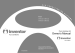
USER’S MANUAL Mini-Split Air Conditioner YEHJZH009-24BAM1ABX YEHJZH009-24BAM1AKX Read this manual before installation and operation Make sure that it is well kept for later reference If you have lost the Owner’s Manual, please sent email to [email protected] for electronic version. UYHJZHAMQ-140505 Content Operation Notices Precautions............................................................................................................ 1 Parts Name............................................................................................................ 6 Screen Operation Guide Buttons on remote controller..................................................................................7 Introduction for icons on display screen.................................................................7 Introduction for buttons on remote controller......................................................... 8 Introduction for special function............................................................................13 Operation guide................................................................................................... 15 Replacement of batteries in remote controller......................................................15 Emergency operation .......................................................................................... 16 Maintenance Clean and Maintenance........................................................................................16 Malfunction Malfunction analysis ............................................................................................ 19 Installation Notice Installation dimension diagram ............................................................................ 23 Tools for installation............................................................................................. 24 Selection of installation location .......................................................................... 24 Requirements for electric connection .................................................................. 25 Installation Installation of indoor unit...................................................................................... 26 Check after installation ........................................................................................ 31 Test and operation Test operation.......................................... ............................................................31 Attachment Configuration of connection pipe ......................................................................... 32 Pipe expanding method ....................................................................................... 34 Wired Controller (Optional).................................................................................. 35 This marking indicates that this product should not be disposed with other household wastes throughout the EU. To prevent possible harm to the environment or human health from uncontrolled waste disposal, recycle it responsibly to promote the sustainable reuse of material resources. To return your used device, please use the return and collection systems or contact the retailer where the product was purchased. They can take this product for environmental safe recycling. R410A(R32/125: 50/50): 1975 Precautions WARNING Operation and Maintenance This appliance can be used by children aged from 8 years and above and persons with reduced physical, sensory or mental capabilities or lack of experience and knowledge if they have been given supervision or instruction concerning use of the appliance in a safe way and understand the hazards involved. Children shall not play with the appliance. Cleaning and user maintenance shall not be made by children without supervision. Do not connect air conditioner to multi-purpose socket. Otherwise, it may cause fire hazard. Do disconnect power supply when cleaning air conditioner. Otherwise, it may cause electric shock. . If the supply cord is damaged, it must be replaced by the manufacturer, its service agent or similarly qualified persons in order to avoid a hazard. Do not wash the air conditioner with water to avoid electric shock. Do not spray water on indoor unit. It may cause electric shock or malfunction. After removing the filter, do not touch fins to avoid injury. Do not use fire or hair dryer to dry the filter to avoid deformation or fire hazard. 1 Precautions WARNING Maintenance must be performed by qualified professionals. Otherwise, it may cause personal injury or damage. Do not repair air conditioner by yourself. It may cause electric shock or damage. Please contact dealer when you need to repair air conditioner. Do not extend fingers or objects into air inlet or air outlet. It may cause personal injury or damage. Do not block air outlet or air inlet. It may cause malfunction. Do not spill water on the remote controller, otherwise the remote controller may be broken. When below phenomenon occurs, please turn off air conditioner and disconnect power immediately, and then contact the dealer or qualified professionals for service. Ɣ Power cord is overheating or damaged. Ɣ There’s abnormal sound during operation. Ɣ Circuit break trips off frequently. Ɣ Air conditioner gives off burning smell. Ɣ Indoor unit is leaking. If the air conditioner operates under abnormal conditions, it may cause malfunction, electric shock or fire hazard. When turning on or turning off the unit by emergency operation switch, please press this switch with an insulating object other than metal. Do not step on top panel of outdoor unit, or put heavy objects. It may cause damage or personal injury. 2 Precautions WARNING Attachment Installation must be performed by qualified professionals. Otherwise, it may cause personal injury or damage. Must follow the electric safety regulations when installing the unit. According to the local safety regulations, use qualified power supply circuit and circuit break. Do install the circuit break. If not, it may cause malfunction. An all-pole disconnection switch having a contact separation of at least 3mm in all poles should be connected in fixed wiring. Including an circuit break with suitable capacity, please note the following table. Air switch should be included magnet buckle and heating buckle function, it can protect the circuit-short and overload. Air Conditioner should be properly grounded. Incorrect grounding may cause electric shock. Don't use unqualified power cord. Make sure the power supply matches with the requirement of air conditioner. Unstable power supply or incorrect wiring or malfunction. Please install proper power supply cables before using the air conditioner. Properly connect the live wire, neutral wire and grounding wire of power socket. Be sure to cut off the power supply before proceeding any work related to electricity and safety. 3 Precautions WARNING Do not put through the power before finishing installation. If the supply cord is damaged, it must be replaced by the manufacturer, its service agent or similarly qualified persons in order to avoid a hazard. The temperature of refrigerant circuit will be high, please keep the interconnection cable away from the copper tube. The appliance shall be installed in accordance with national wiring regulations. Installation must be performed in accordance with the requirement of NEC and CEC by authorized personnel only The air conditioner is the first class electric appliance. It must be properly grounding with specialized grounding device by a professional. Please make sure it is always grounded effectively, otherwise it may cause electric shock. The yellow-green wire in air conditioner is grounding wire, which can't be used for other purposes. The grounding resistance should comply with national electric safety regulations. The appliance must be positioned so that the plug is accessible. All wires of indoor unit and outdoor unit should be connected by a professional. If the length of power connection wire is insufficient, please contact the supplier for a new one. Avoid extending the wire by yourself. 4 Precautions WARNING For the air conditioner with plug, the plug should be reachable after finishing installation. For the air conditioner without plug, an circuit break must be installed in the line. If you need to relocate the air conditioner to another place, only the qualified person can perform the work. Otherwise, it may cause personal injury or damage. Select a location which is out of reach for children and far away from animals or plants.If it is unavoidable, please add the fence for safety purpose. The indoor unit should be installed close to the wall. Instructions for installation and use of this product are provided by the manufacturer. Working temperature range Maximum cooling Maximum heating Indoor side DB/WB(ć ) 32/23 27/- Outdoor side DB/WB(ć ) 43/26 24/18 NOTICE: Ɣ The operating temperature range (outdoor temperature) for cooling is -15 ~43 ; Heating temperature range for the model without electric heating belt for chassis is -15 ~43 Heating temperature range for the model with electric heating belt for chassis is -20 ~43 . 5 Parts Name Indoor Unit air inlet aux.button horizontal louver air outlet cooling indicator power indicator receiver window display heating indicator temp. indicator drying indicator (Display content or position may be different from above graphics, please refer to actual products) remote controller NOTICE: Actual product may be different from above graphics, please refer to actual products. 6 Buttons on remote controller 1 ON/OFF button 2 FAN button 3 MODE button 4 +/- button 5 TURBO button 6 button 2 2 5 6 4 4 11 3 9 7 3 8 1 13 10 12 14 16 7 8 CLOCK button 1 15 9 TIMER ON/ TIMER OFF button 10 TEMP button 11 (before opening cover (after opening cover button / button 12 I FEEL button 1 ON/OFF button 13 LIGHT button 2 FAN button 14 X-FAN button 3 MODE button 15 QUIET button 4 +/- button 16 SLEEP button Introduction for icons on display screen I feel Quiet Set fan speed Turbo mode Send signal Healthy mode Scavenging functions 8ć(46̧) heating function Operation mode Auto mode Cool mode Set temperature X-FAN function Dry mode Fan mode Heat mode Set time TIMER ON /TIMER OFF Clock Sleep mode Child lock Up & down swing Left & right swing Light Temp. display type : Set temp. : Indoor ambient temp. : Outdoor ambient temp. 7 Introduction for buttons on remote controller Note: Ɣ After putting through the power, the air conditioner will give out a sound. Operation indictor " " is ON (red indicator). After that, you can operate the air conditioner by using remote controller. ƔUnder on status, pressing the button on the remote controller, the signal icon " " on the display of remote controller will blink once and the air conditioner will give out a “de” sound, which means the signal has been sent to the air conditioner. Ɣ8QGHURff status, set temperature and clock icon will be displayed on the display of remote controller (If timer on, timer off and light functions are set, the corresponding icons will be displayed on the display of remote controller at the same time); Under on status, the display will show the corresponding set function icons. 1 ON/OFF button Press this button, the unit will be turned on, press it once more, the unit will be turned off. Sleep function will be canceled, while unit off. 2 FAN button Press this button, Auto, Low, Medium-low, Medium, Medium-high, High speed can be circularly selected. After powered on, Auto fan speed is default. Under DRY mode, Low fan speed only can be set up. ATUO Low fan Medium-low fan Note: It’s Low fan speed under Dry mode. Medium fan Medium-high fan High fan Note: If matching with smart zone controller for operation, under auto fan speed, the fan speed display on smart zone controller will always be maintained at “auto high fan”. 3 MODE button Press this button, Auto, Cool, Dry, Fan, Heat mode can be selected circularly. Auto mode is default while power on. Under Auto mode, the temperature will not be displayed; Under Heat mode, the initial value is 28ć(82̧); Under other modes, the initial value is 25ć(77̧). AUTO COOL DRY FAN HEAT (only for cooling and heating unit. As for cooling only unit, it won’t have any action when it receives the signal of heating operation.) 4 +/- button Presetting temperature can be increased. Press this button, the temperature can be set up, continuously press this button and hold for two seconds, the relative contents can quickly change, until unhold this button and send the order that the ć(̧) signal will be displayed all the time. The temperature adjustment is unavailable under the Auto mode, but the order can be sent if pressing this button. Temperature of Celsius degree setting: 16-30; for Fahrenheit degree setting: 61-86. 8 Introduction for buttons on remote controller Presetting temperature can be decreased. Press this button, the temperature can be set up, continuously press this button and hold for two seconds, the relative contents can quickly change, until unhold this button and send the order that the Ƈ (Ɖ) signal will be displayed all the time. The temperature adjustment is unavailable under the Auto mode, but the order can be sent by if pressing this button. 5 TURBO button Under Cool or Heat mode, press this button can turn on or turn off the Turbo function. After the Turbo function turned on, the signal of Turbo will display. The signal will be automatically cancelled if changing the mode or fan speed. 6 button Press this button to set left & right swing angle cycling as below: OFF 7 button Press this button to set swing angle, which circularly changes as below: OFF This remote controller is universal. If it receives threes kinds of following status, the swing angle will remain original. If guide louver is stopped when it is swinging up and down, it will remian its present position. indicates guide louver swings back and forth in the five places, as shown in the figure. 8 CLOCK button Press this button, the clock can be set up, signal blink and display. Within 5 seconds, the value can be adjusted by pressing + or - button, if continuously press this button for 2 seconds above, in every 0.5 seconds, the value on ten place ofMinutewill be increased 1. During blinking, repress the Clock button or Confirm button, signal will be constantly displayed and it denotes the setting succeeded. After powered on, 12:00 is defaulted to display and signal will be displayed. If there is signal be displayed that denotes the current time value is Clock value, otherwise is Timer value. 9 TIMER ON/TIMER OFF button Timer On setting: Sign al “ON” will blink and display, signal will conceal, the numerical section will become the timer on setting status. During 5 seconds blink, by pressing + or - button to adjust the time value of numerical section, every press of that button, the value will be increased or decreased 1 minute. Hold pressing + or - 9 Introduction for buttons on remote controller button, 2 seconds later, it quickly change, the way of change is: During the initial 2.5 seconds, ten numbers change in the one place of minute, then the one place is constant, ten numbers change in the tens place of minu te at 2.5 seconds speed and carry. During 5s blink, press the Timer button, the timer setting succeeds. The Timer On has been set up, repress the timer button, the Timer On will be canceled. Before sett ing the Timer, please adjust the Clock to the current actual time. One press this key to enter into TIMER OFF setup, in which case the TIMER OFF icon will blink. The method of setting is the sameas for TIMER ON. 10 TEMP button Press this button, you can see indoor set temperature, indoor ambient temperature or outdoor ambient temperature on indoor unit’s display. The setting on remote controller is selected circularly as below: no display When selecting " " with remote controller or no display, temperature indicator on indoor unit displays set temperature; When selecting " " with remote controller, temperature indicator on indoor unit displays indoor ambient temperature; When selecting " " with remote controller, temperature indicator on indoor unit displays outdoor ambient temperature. 3s later it will return to the setting temprature or it depends on the other received signal within 3s. Attention: When displaying the outdoor ambient, the displaying range is 0-60Ƈ When it goes beyond the range, it keeps the threshold data (the smallest—0Ƈ and the largest 60Ƈ). Warm tips: When operating buttons on the cover please make sure the cover is closed completely. 11 / button Press this button to achieve the on and off of healthy and scavenging functions in operation status. Press this button for the first time to start scavenging function; LCD displays " ". Press the button for the second time to start healthy and scavenging functions simultaneously; LCD displays " " and " ". Press this button for the third time to quit healthy and scavenging functions simultaneously. Press the button for the fourth time to start healthy function; LCD display " ". Press this button again to repeat the operation above. NOTE: This function is applicable to partial of models. 12 I FEEL button Press this button once, to turn on the I FEEL function, then the figure of "I FEEL" will be displayed, after every press of other function button, every 200ms to send I FEEL once, after this function started, the remote controller will send temperature to the main un it in every 10 minutes. When repress this button, this function will be turned off. 10 Introduction for buttons on remote controller 13 LIGHT button Press this button at unit On or Off status, Light On and Light Off can be set up. After powered on, Light On is defaulted. 14 X-FAN button Pressing X-FAN button in COOL or DRY mode, the icon is displayed and the indoor fan will continue operation for 2 minutes in order to dry the indoor unit even though you have turned off the unit. After energization, X-FAN OFF is defaulted. X-FAN is not available in AUTO, FAN or HEAT mode. 15 QUIET button Press this button, the Quiet status is under the Auto Quiet mode (display " " and "Auto" signal) and Quiet mode (display " " singal) and Quiet OFF (there is no signal of " " displayed), after powered on, the Quiet OFF is defaulted. Under the Quiet mode (Display " " signal). 16 SLEEP button Press this button, can select Sleep 1 ( ), Sleep 2 ( ), Sleep 3 ( ) and cancel the Sleep, circulate between these, after electrified, Sleep Cancel is defaulted. Sleep 1 is Sleep mode 1, in Cool, Dehumidify modes: sleep status after run for one hour, the main unit setting temperature will increase 1Ƈ, 2 hours, setting temperature increased 2Ƈ, the unit will run at this setting temperature; In Heat mode: sleep status after run for one hour, the setting temperature will decrease 1Ƈ, 2 hours, setting temperature will decrease 2Ƈ, then the unit will run at this setting temperature. Sleep 2 is sleep mode 2, that is air conditioner will run according to the presetting a group of sleep temperature curve. In Cool mode: (1) When setting the initial temperature 16Ƈ-23Ƈ, after turned on Sleep function, the temperature will be increased 1Ƈ in every hour, after 3Ƈ the temperature will be maintained, after 7hours, the temperature will be decreased 1Ƈ, after that the unit will keep on running under this temperature; (2) When setting the initial temperature 24Ƈ-27Ƈ, after turned on Sleep function, the temperature will be increased 1Ƈ in every hour, after 2Ƈ the temperature will be maintained, after 7hours, the temperature will be decreased 1Ƈ, after that the unit will keep on running under this temperature; (3) When setting the initial temperature 28Ƈ-29Ƈ, after turned on Sleep function, the temperature will be increased 1Ƈ in every hour, after 1Ƈ the temperature will be maintained, after 7hours, the temperature will be decreased 1Ƈ, after that the unit will keep on running under this temperature; 11 Introduction for buttons on remote controller (4) When setting the initial temperature 30Ƈ, under this temperature setting, after 7hours, the temperature will be decreased 1Ƈ, after that the unit will keep on running under this temperature; In Heat mode: (1) Under the initial presetting temperature 16Ƈ, it will run under this setting temperature all along. (2) Under the initial presetting temperature17Ƈ-20Ƈ, after Sleep function started up, the temperature will decrease 1Ƈ in every hour, after 1Ƈ decreased, this temperature will be maintained. (3) Under the initial presetting temperature 21Ƈ-27Ƈ, after Sleep function started up, the temperature will decrease 1Ƈ in every hour, after 2Ƈ decreased, this temperature will be maintained. (4) Under the initial presetting temperature 28Ƈ-30Ƈ, after Sleep function started up, the temperature will decrease 1Ƈ in every hour, after 3Ƈ decreased, this temperature will be maintained. Sleep 3 - the sleep curve setting under Sleep mode by DIY: (1) Under Sleep 3 mode, press "Turbo" button for a long time, remote controller enters into user individuation sleep setting status, at this time, the time of remote controller will display "1hour", the setting temperature "88" will display the corresponding temperature of last setting sleep curve and blink (The first entering will display according to the initial curve setting value of original factory); (2) Adjust "+" and "-" button, could change the corresponding setting temperature, after adjusted, press "Trubo" button for confirmation; (3) At this time, 1hour will be automatically increased at the timer postion on the remote controller, (that are "2hours" or "3hours" or "8hours"), the place of setting temperature "88" will display the corresponding temperature of last setting sleep curve and blink; (4) Repeat the above step (2)~(3) operation, until 8hours temperature setting finished, sleep curve setting finished, at this time, the remote controller will resume the original timer display; temperature display will resume to original setting temperature. Sleep3 - the sleep curve setting under Sleep mode by DIY could be inquired: The user could accord to sleep curve setting method to inquire the presetting sleep curve, enter into user individuation sleep setting status, but do not change the temperature, press "Turbo" button directly for confirmation. Note: In the above presetting or enquiry procedure, if continuously within10s, there is no button pressed, the sleep curve setting status will be automatically quit and resume to display the original displaying. In the presetting or enquiry procedure, press "ON/OFF" button, "Mode" button, "Timer" button or "Sleep" button, the sleep curve setting or enquiry status will quit similarly. 12 Introduction for special function About X-FAN function This function indicates that moisture on evaporator of indoor unit will be blowed after the unit is stopped to avoid mould. 1. Having set X-FAN function on: After turning off the unit by pressing ON/OFF button indoor fan will continue running for about 2 min. at low speed. In this period, press X-FAN button to stop indoor fan directly. 2. Having set X-FAN function off: After turning off the unit by pressing ON/OFF button, the complete unit will be off directly. About AUTO RUN When AUTO RUN mode is selected, the setting temperature will not be displayed on the LCD, the unit will be in accordance with the room temp. automatically to select the suitable running method and to make ambient comfortable. About turbo function If start this function, the unit will run at super-high fan speed to cool or heat quickly so that the ambient temp. approachs the preset temp. as soon as possible. About lock Press + and - buttons simultaneously to lock or unlock the keyboard. If the remote controller is locked, the icon will be displayed on it, in which case, press any button, the mark will flicker for three times. If the keyboard is unlocked, the mark will disappear. About swing up and down 1. Press swing up and down button continuously more than 2s, the m ain unit will swing backand forth from up to down , and then loosen the button, the unit will stop swing and present position of guide louver will be kept immediately. 2. Under swing up and down mode, when the status is switched from off to , if press this button again 2s later, status will switch to off status directly; If press this button again within 2s, the change of swing status will also depend on the circulation sequence stated above. About swing left and right 1. Press swing left and right button continuously more than 2s, the main unit will swing back and forth from left to right, and then loosen the button, the unit will stop swing and present position of guide louver will be kept immediately. 2. Under swing left and right mode, when the status is switched from off to , if press this button again 2s later, status will switch to off status directly; if press this button again within 2s, the change of swing status will also depend on the circulation sequence stated above. 13 Introduction for special function About switch between Fahrenheit and Centigrade Under status of unit off, press MODE and - buttons simultaneously to switch ć and ̧. Combination of "TEMP" and "CLOCK" buttons: About Energy - saving Function Press “TEMP” and “CLOCK” simultaneously in COOL mode to start energy-saving function. Nixie tube on the remote controller displays “SE”. Repeat the operation to quit the function. Combination of "TEMP" and "CLOCK" buttons: About 8ć Heating Function 3UHVV³7(03´DQG³&/2&.´VLPXOWDQHRXVO\LQ+($7PRGHWRVWDUWć Heating Function Nixie tube on the remote controller displays “ ” and a seleFWHGWHPSHUDWXUHRI³ć”. (46̧ if Fahrenheit is adopted). Repeat the operation to quit the function. Note: If matching with smart zone controller for operation, the display on smart zone controller will be maintained the original status. About auto Quiet function When quiet function is selected: 1. Under cooling mode: indoor fan operates at notch 4 speed. 10 minutes later or when LQGRRUDPELHQWWHPSHUDWXUHćLQGRRUIDQZLOORSHUDWHDWQRWFKVSHHGRUTXLHW mode according to the comparison between indoor ambinet temperature and set temperature. 8QGHUKHDWLQJPRGHLQGRRUIDQRSHUDWHVDWQRWFKVSHHGRUquiet mode according to the comparison between indoor ambient temperature and set temperature. 8QGHUGU\IDQPRGHLQGRRUIDQRSHUDWHVDWTXLHWPRGH 4. Under auto mode: the indoor fan operates at the auto quiet mode according to actual cooling, heating or fan mode. About Sleep function Under the Fan and Auto mode, the Sleep function cannot be set up, under Dehumidify mode, only Sleep 1 can be selected. Select and enter into any kind of Sleep mode, the Quiet function will be attached and stared, different Quiet status could be optional and turned off. 14 Operation guide General operation 4 1. After powered on, press ON/OFF button, the unit will start to run. (Note: When it is powered on, the guide louver of main unit will close automatically.) 2. Press MODE button, select desired running mode. 3. Pressing + or - button, to set the desired temperature (It is unnecessary to set the temp. at AUTO mode.) 4. Pressing FAN button, set fan speed, can select AUTO FAN, LOW, MEDIUM-LOW, MEDIUM, MEDIUM-HIGH and HIGH. 5. Pressing and button, to select the swing. 3 5 2 1 Optional operation 4 1. Press SLEEP button, to set sleep. 2. Press TIMER ON and TIMER OFF button, can set the scheduled timer on or timer off. 3. Press LIGHT button, to control the on and off of the displaying part of the unit (This function may be not available for some units). 4. Press TURBO button, can realize the ON and OFF of TURBO function. 2 1 3 Replacement of batteries in remote controller battery 1. Press the back side of remote controller marked reinstall the cover of battery box along the arrow direction. 2. Replace two 7# (AAA 1.5V) dry batteries, and make sure the position of "+" polar and "-" polar are correct. 3. Reinstall the cover of battery box. remove Cover of battery box NOTICE Ɣ'XULQJRSHUDWLRQSRLQWWKHUHPRWHFRntrol signal sender at the receiving window on indoor unit. Ɣ7KHGLVWDQFHEHWZHHQVLJQDOVHQGHUand receiving window should be no more than 8m, and there should be no obstacles between them. Ɣ6LJQDOPD\EHLQWHUIHUHGHDVLO\LQWKH room where there is fluorescent lamp or wireless telephone; remote controller should be close to indoor unit during operation. Ɣ5HSODFHQHZEDWWHULHVRIWKHVDPHPRGHOZKHQUHSODFHPHQWLVUHTXLUHG Ɣ:KHQ\RXGRQ¶WXVHUHPRWHFRQWUROOHUIRUDORQJWLPHSOHDVHWDNHRXWWKH batteries. Ɣ,IWKHGLVSOD\RQUHPRWHFRQWUROOHULVIX]]\RUWKHUH¶VQRGLVSOD\SOHDVH replace batteries. 15 Emergency operation If remote controller is lost or damaged, please use auxiliary button to turn on or turn off the air conditioner. The operation in details are as below: air conditioner. When the air conditioner is turned on, it will operate under auto mode. panel aux. button WARNING: Use insulated object to press the auto button Clean and Maintenance WARNING Ŷ Turn off the air conditioner and disconnect the power before cleaning the air conditioner to avoid electric shock. Ŷ'RQRWZDVKWKHDLUFRQGLWLRQHUZLWKZDWHUWRDYRLGHOHFWULFVKRFN Ŷ'RQRWXVHYRODWLOHOLTXLGWRFOHDQWKHDLUFRQGLWLRQHr. Clean surface of indoor unit When the surface of indoor unit is dirty, it is recommended to use a soft dry cloth or wet cloth to wipe it. NOTICE: Ɣ'RQRWUHPRYHWKHSDQHOZKHQFOHDQLQJLW 16 Clean and Maintenance 1 Open panel 3 Pull out the panel to a certain Ɣ8VHGXVWFDWFKHURUZDWHUWR WKHZDWHUEHORZć ) to clean LWDQGWKHQSXWLWLQDVKDG\ DQGFRROSODFHWRGU\. 2 4 panel cover tightl\. WARNING operation environment, clean frequency can be increased. 17 Clean and Maintenance NOTICE: Checking before use-season 1. Check whether air inlets are blocked. 2. Check whether air switch,plug and socket are in good condition. &KHFNZKHWKHU¿OWHULVFOHDQ 4. Check whether drainage pipe is damaged. NOTICE: Checking after use-season 1. Disconnect power supply. &OHDQ¿OWHUDQGLQGRRUXQLW’s panel. Notice for recovery 1. Many packing materials are recyclable materials. Please dispose them in appropriate recycling unit. 2. If you want to dispose the air conditioner, please contact local dealer or consultant service center for the correct disposal method. 18 Malfunction analysis General phenomenon analysis Please check below items before asking for maintenance. If the malfunction still Phenomenon Check items Solution Ɣ:KHWKHULW VLQWHUIHUHGVHYHUHO\ Ɣ3XOORXWWKHSOXJ5HLQVHUW (such as static electricit\, stable the plug after about 3min, and voltage)? then turn on the unit again. Indoor unit can’t receive remote controller’s signal or remote controller has no action. Ɣ:KHWKHUUHPRWHFRQWUROOHULV within the signal receiving range? Ɣ6LJQDOUHFHLYLQJUDQJHLVP Ɣ:KHWKHUWKHUHDUHREVWDFOHV" Ɣ5HPRYHREVWDFOHV ƔSelect proper angle and point Ɣ:KHWKHUUHPRWHFRQWUROOHULV pointing at the receiving WKHUHPRWHFRQWUROOHUDWWKHUH window? ceiving window on indoor unit. Ɣ,VVHQVLWLYLW\RIUHPRWHFRQWUR Ɣ&KHFNWKHEDWWHULHV,IWKH power of batteries is too low, OOHUORZIX]]\GLVSOD\DQGQR please replace them. GLVSOD\" Ɣ&KHFNZKHWKHUUHPRWHFRQW Ɣ1RGLVSOD\ZKHQRSHUDWLQJ roller appears to be damaged. remote controller? ,I\HVUHSODFHLW Ɣ)OXRUHVFHQWODPSLQURRP" Ɣ Take the remote controller close to indoor unit. DQGWKHQWU\LWDJDLQ 1RDLU emitted from indoor unit Ɣ Air inlet or air outlet of indoor unit is blocked? Ɣ(OLPLQDWHREVWDFOHV Ɣ8QGHUKHDWLQJPRGHLQGRRU temperature is reached to set temperature? Ɣ $IWHUUHDFKLQJWRVHWWHPSHU DWXUHLQGRRUXQLWZLOOVWRSEO owing out air. Ɣ+HDWLQJPRGHLVWXUQHGRQMXVW Ɣ,QRUGHUWRSUHYHQWEORZLQJ now? out cold air, indoor unit will be VWDUWHGDIWHUGHOD\LQJIRUVHY HUDOPLQXWHVZKLFKLVDQRU mal phenomenon. 19 Malfunction analysis 3KHQRPHQRQ $LUFRQGLW LRQHUFDQ¶W RSHUDWH &KHFNLWHPV 6ROXWLRQ Ɣ3RZHUIDLOXUH" Ɣ:DLWXQWLOSRZHUUHFRYHU\ Ɣ,VSOXJORRVH" Ɣ5HLQVHUWWKHSOXJ Ɣ$LUVZLWFKWULSVRIIRUIXVHLV EXUQWRXW" Ɣ$VNSURIHVVLRQDOWRUHSODFH DLUVZLWFKRUIXVH Ɣ:LULQJKDVPDOIXQFWLRQ" Ɣ$VNSURIHVVLRQDOWRUHSODFHLW Ɣ8QLWKDVUHVWDUWHGLPPHGLDWHO\ Ɣ:DLWIRUPLQDQGWKHQWXUQ DIWHUVWRSSLQJRSHUDWLRQ" RQWKHXQLWDJDLQ Ɣ:KHWKHUWKHIXQFWLRQVHWWLQJ IRUUHPRWHFRQWUROOHULV FRUUHFW" 0LVWLVHP LWWHGIURP Ɣ,QGRRUWHPSHUDWXUHDQGKXP LQGRRUXQLW¶V LGLW\LVKLJK" DLURXWOHW 6HWWHPSHU DWXUHFDQ¶W EHDGMXVWHG &RROLQJ KHDWLQJ HIIHFWLV QRWJRRG Ɣ5HVHWWKHIXQFWLRQ Ɣ%HFDXVHLQGRRUDLULVFRROHG UDSLGO\$IWHUDZKLOHLQGRRU WHPSHUDWXUHDQGKXPLGLW\ZLOO EHGHFUHDVHDQGPLVWZLOO GLVDSSHDU Ɣ8QLWLVRSHUDWLQJXQGHUDXWR PRGH" ƔTHPSHUDWXUHFDQ¶WEHDGMX VWHGXQGHUDXWRPRGH 3OHDVHVZLWFKWKHRSHUDWLRQ PRGHLI\RXQHHGWRDGMXVW WHPSHUDWXUH ƔYRXUUHTXLUHGWHPSHUDWXUH H[FHHGVWKHVHWWHPSHUDWXUH UDQJH" Ɣ6HWWHPSHUDWXUHUDQJH ć ać ƔVROWDJHLVWRRORZ" Ɣ:DLWXQWLOWKHYROWDJH UHVXPHVQRUPDO Ɣ)LOWHULVGLUW\" Ɣ6HWWHPSHUDWXUHLVLQSURSHU UDQJH" ƔAGMXVWWHPSHUDWXUHWRSURSHU UDQJH Ɣ'RRUDQGZLQGRZDUHRSHQ" Ɣ&ORVHGRRUDQGZLQGRZ 20 Malfunction analysis Phenomenon Odours are emitted Air conditioner operates abnormally suddenly “Water ÀRZLQJ´ noise Cracking noise Check items Solution Ɣ:KHWKHUWKHUH¶VRGRXUVRXUFH Ɣ(OLPLQDWHWKHRGRXUVRXUFH such as furniture and cigarette, Ɣ&OHDQWKH¿OWHU etc. Ɣ:KHWKHUWKHUH¶VLQWHUIHUHQFH such as thunder, wireless devices, etc. Ɣ'LVFRQQHFWSRZHUSXWEDFN power, and then turn on the unit again. Ɣ$LUFRQGLWLRQHULVWXUQHGRQRU turned off just now? Ɣ7KHQRLVHLVWKHVRXQGRI UHIULJHUDQWÀRZLQJLQVLGH the unit, which is a normal phenomenon. Ɣ$LUFRQGLWLRQHULVWXUQHGRQRU turned off just now? 21 Ɣ7KLVLVWKHVRXQGRIIULFWLRQ caused by expansion and/or contraction of panel or other parts due to the change of temperature. Malfunction analysis Error Code Ɣ:KHQDLUFRQGLWLRQHUVWDWXVLVDEQRUPDlWHPSHUDWXUHLQGLFDWRURQLQGRRUXQLWZLOO DWLRQRIHUURUFRGH ,QGRRU GLVSOD\ (UURUFRGH $ERYHLQGLFDWRUGLDJUDPLVRQO\ IRUUHIHUHQFH3OHDVHUHIHUWR DFWXDOSURGXFWIRUWKHDFWXDO LQGLFDWRUDQGSRVLWLRQ (UURUFRGH TURXEOHVKRRWLQJ +HDWLQJLQGLFDWRU 21V2))V 0HDQVGHIURVWLQJVWDWXV,W¶VWKHQRUPDOSKHQRPHQRQ ) 3OHDVHFRQWDFWTXDOLILHGSURIHVVLRQDOVIRUVHUYLFH ) 3OHDVHFRQWDFWTXDOLILHGSURIHVVLRQDOVIRUVHUYLFH & 3OHDVHFRQWDFWTXDOLILHGSURIHVVLRQDOVIRUVHUYLFH H6 ,WFDQEHHOLPLQDWHGDIWHUUHVWDUWLQJWKHXQLW,IQRWSOHDVH FRQWDFWTXDOLILHGSURIHVVLRQDOVIRUVHUYLFH 1RWH,IWKHUH UHRWKHUHUURUFRGHVSOHDVHFRQWDFWTXDOLILHGSURIHVVLRQDOVIRU VHUYLFH WARNING Ŷ:KHQEHORZSKHQRPHQRQRFFXUVSOHDVHWXUQRIIDLUFRQGLWLRQHUDQGGLVFRQ IRUVHUYLFH Ɣ3RZHUFRUGLVRYHUKHDWLQJRUGDPDJHG Ɣ7KHUH¶VDEQRUPDOVRXQGGXULQJRSHUDWLRQ Ɣ$LUVZLWFKWULSVRIIIUHTXHQWO\ Ɣ$LUFRQGLWLRQHUJLYHVRIIEXUQLQJVPHOO Ɣ,QGRRUXQLWLVOHDNLQJ Ŷ,IWKHDLUFRQGLWLRQHURSHUDWHVXQGHUDEQRUPDOFRQGLWLRQVLWPD\FDXVH 22 At least 15cm Space to the ceiling Installation dimension diagram Space to the wall At least 15cm At least 15cm Space to the wall m At ce a Sp s lea he ot At least 250cm 0c 0 t3 n tio uc str ob t 23 Tools for installation 1 Level meter 2 Screw driver 3 Impact drill 4 Drill head 5 Pipe expander 6 Torque wrench 7 Open-end wrench 8 Pipe cutter 9 Leakage detector 10 Vacuum pump 11 Pressure meter 12 Universal meter 13 Inner hexagon spanner Note: 14 Measuring tape Ɣ3OHDVHFRQWDFWWKHORFDODJHQWIRULQVWDOODWLRQ Ɣ'RQ WXVHXQTXDOL¿HGSRZHUFRUG Selection of installation location Basic requirement Installing the unit in the following places maycause malfunction. If it is unavoidable, please consult the local dealer: 1. The place with strong heat sources, YDSRUVÀDPPDEOHRUH[SORVLYHJDV, or volatile objects spread in the air. 2. The place with high-frequency devices (such as welding machine, medical equipment). 3. The place near coast area. 4. The place with oil or fumes in the air. 5. The place with sulfureted gas. 6. Other places with special circumstances. 7. Do not use the unit in the immediate surroundings of a laundry a bath a shower or a swimming pool. Indoor unit 1. There should be no obstruction near air inlet . 2. Select a location where the condensation water can be dispersed easily and ZRQ WDIIHFWRWKHUSHRSOH 3. Select a location which is convenient to connect the outdoor unit and near the power socket. 4. Select a location which is out of reach for children. 7KHORFDWLRQVKRXOGEHDEOHWRZLWKVWDQGWKHZHLJKWRILQGRRUXQLWDQGZRQ W increase noise and vibration. 7KHDSSOLDQFHPXVWEHLQVWDOOHGPDERYHÀRRU 'RQ WLQVWDOOWKHLQGRRUXQLWULJKWDERYHWKHHOHFWULFDSSOLDQFH 3OHDVHWU\\RXUEHVWWRNHHSZD\IURPÀXRUHVFHQWODPS 24 Requirements for electric connection Safety precaution 1. Must follow the electric safety regulations when installing the unit. $FFRUGLQJWRWKHORFDOVDIHW\UHJXODWLRQVXVHTXDOL¿HGSRZHUVXSSO\FLUFXLWDQG air switch. 3. Make sure the power supply matches with the requirement of air conditioner. Unstable power supply or incorrect wiring or malfunction. Please install proper power supply cables before using the air conditioner. 4. Properly connect the live wire, neutral wire and grounding wire of power socket. 5. Be sure to cut off the power supply before proceeding any work related to electricity and safety. 'RQRWSXWWKURXJKWKHSRZHUEHIRUH¿QLVKLQJLQVWDOODWLRQ 7. If the supply cord is damaged, it must be replaced by the manufacturer, its VHUYLFHDJHQWRUVLPLODUO\TXDOL¿HGSHUVRQVLQRUGHUWRDYRLGDKD]DUG 8. The temperature of refrigerant circuit will be high, please keep the interconnection cable away from the copper tube. 9. The appliance shall be installed in accordance with national wiring regulations. 10.Installation must be performed in accordance with the requirement of NEC DQG&(&E\DXWKRUL]HGSHUVRQQHORQO\ Grounding requirement 7KHDLUFRQGLWLRQHULVWKH¿UVWFODVVHOHFWULFDSSOLDQFH,WPXVWEHSURSHUO\ JURXQGLQJZLWKVSHFLDOL]HGJURXQGLQJGHYLFHE\DSURIHVVLRQDO3OHDVHPDNH sure it is always grounded effectively, otherwise it may cause electric shock. 7KH\HOORZJUHHQZLUHLQDLUFRQGLWLRQHULVJURXQGLQJZLUHZKLFKFDQ WEHXVHG for other purposes. 3. The grounding resistance should comply with national electric safety regulations. 4. The appliance must be positioned so that the plug is accessible. 5. An all-pole disconnection switch having a contact separation of at least 3mm in DOOSROHVVKRXOGEHFRQQHFWHGLQ¿[HGZLULQJ)RUPRGHOVZLWKDSRZHUSOXJ make sure the plug is within reach after installation. 25 Installation of indoor unit Step one: choosing installation location rm it with the client. Step two: install wall-mounting frame 1. Hang the wall-mounting frame on the wall; adjust it in horizontal position with the plastic expansion particles in the holes. 3. Fix the wall-mounting frame on the wall with tapping screws (ST4.2X25TA) and . Step three: open piping hole 1. Choose the position of piping hole according to the direction of outlet pipe. The position of piping hole should be a little lower than the wall-mounted frame, shown as below. 、 、12K Wall Mark in the middle of it 18K Level meter Space to the wall above PP Wall Wall Space to the wall above PP Space to the wall above PP Left ĭPP Rear piping hole Mark in the middle of it Right ĭPP Rear piping hole Left ĭPP Rear piping hole Wall Level meter Space to the wall above PP Right ĭPP Rear piping hole 24K Wall Mark in the middle of it Space to the wall above PP Left ĭPP Rear piping hole Level meter Wall Space to the wall above PP Right ĭPP Rear piping hole Note: Please select the corresponding installation dimensional drawing according to actual wall-mounted plate. 2. Open a piping hole with the diameter oIĭRQWKHVHOHFWHGRXWOHWSLSH position. In order to drain smoothly, slant the piping hole on the wall slightly GRZQZDUGWRWKHRXWGRRUVLGHZLWKWKHJUDGLHQWRI 26 Installation of indoor unit Indoor outdoor Note: Ɣ3D\DWWHQWLRQWRGXVWSUHYHQWLRQDQG WDNHUHOHYDQWVDIHW\PHDVXUHVZKHQ opening the hole. Ɣ The plastic expansion particles are QRWSURYLGHGDQGVKRXOGEHERXJKW locally. ĭ ĭ 5-10 Step four: outlet pipe 2. When select leading out the pipe from left or right, please cut off the corresponding hole on the bottom case. 1. The pipe can be led out in the direction of right, rear right, left or rear left. right left right left rear right rear left cut off the hole 1. Aim the pipe joint at the corresponding bellmouth. pipe joint union nut pipe 2. Pretightening the union nut with hand. 3. Adjust the torque force by referring to the following sheet. Place the open-end wrench on the pipe joint and place the torque wrench on the union nut. Tighten the union nut with torque wrench. 27 Installation of indoor unit open-end wrench union nut torque wrench pipe Hex nut diameter Tightening torque (N.m) ĭ a ĭ 30~40 ĭ 5a ĭ a ĭ a indoor pipe 4. Wrap the indoor pipe and joint of connection pipe with insulating pipe, and then wrap it with tape. insulating pipe ,IDNLQGRRUXQLWLVWREHFRQQHFWHGZLWK)UHH0DWFKRXWGRRUXQLWDWUDQVLWLRQDO SLSHMRLQWSURYLGHGVKRXOGEHDGGHGDWWKHSLSHMRLQWRILQGRRUXQLWHYDSRUDWRUDVV\ DVWKHSLSHMRLQWRIHYDSRUDWRUDVV\DGRSWVSLSHGLDPHWHURIĭ3OHDVHUHIHUWRVWHS 1-4 during installation. Step six: install drain hose 1. Connect the drain hose to the outlet pipe of indoor unit. drain hose 2. Bind the joint with tape. outlet pipe drain hose outlet pipe tape drain hose Note: Ɣ Add insulating pipe in the indoor drain hose in order to prevent condensation. Ɣ The plastic expansion particles are not provided. insulating pipe Step seven: connect wire of indoor unit panel 1. Open the panel, remove the screw on the wiring cover and then take down the cover. 28 screw wiring cover Installation of indoor unit 2. Make the power connection wire go through the cable-cross hole at the back of indoor unit and then pull it out from the front side. cable-cross hole power connection wire 3. Remove the wire clip; connect the power connection wire to the wiring terminal according to the color; tighten the screw and then fix the power connection wire with wire clip. N(1) 2 3 blue black brown yellow-green outdoor unit connection 4. Put wiring cover back and then tighten the screw. 5. Close the panel. Note: Ɣ All wires of indoor unit and outdoor unit should be connected by a professional. for a new one. Avoid extending the wire by yourself. installation. Ɣ)RUWKHDLUFRQGLWLRQHUZLWKRXWSOXJDQair switch must be installed in the line. The air switch should be all-pole parting and the contact parting distance should be more than 3mm. 29 Installation of indoor unit Step eight: bind up pipe 1. Bind up the connection pipe, power cord and drain hose with the band. indoor unit connection pipe drain hose band indoor and outdoor power cord gas pipe indoor power cord liquid pipe 3. Bind them evenly. 4. The liquid pipe and gas pipe should be bound separately at the end. band drain hose 2. Reserve a certain length of drain hose and power cord for installation when binding them. When binding to a certain degree, separate the indoor power and then separate the drain hose. Note: Ɣ The power cord and control wire can't be crossed or winding. Ɣ The drain hose should be bound at the bottom. Step nine: hang the indoor unit 1. Put the bound pipes in the wall pipe and then make them pass through the wall hole. 2. Hang the indoor unit on the wall-mounting frame. 3. Stuff the gap between pipes and wall hole with sealing gum. 4. Fix the wall pipe. 5. Check if the indoor unit is installed firmly and closed to the wall. indoor wall pipe upper hook outdoor sealing gum lower hook of wall-mounting frame Note: Ɣ'RQRWEHQGWKHGUDLQKRVHWRRH[FHssively in order to prevent blocking. 30 Check after installation Items to be checked Possible malfunction The unit may drop, shake or emit noise. Have you done the refrigerant leakage test? (heating) capacity. It may cause condensation and water dripping. Is water drained well? It may cause condensation and water dripping. Is the voltage of power supply according to the voltage marked on the nameplate? It may cause malfunction or damaging the parts. Is electric wiring and pipeline installed correctly? It may cause malfunction or damaging the parts. Is the unit grounded securely? It may cause electric leakage. Does the power cord follow the speci- It may cause malfunction or damaging the parts. Is there any obstruction in the air inlet and outlet? (heating) capacity. The dust and sundries caused during installation are removed? It may cause malfunction or damaging the parts. The gas valve and liquid valve of connection pipe are open completely? (heating) capacity. Test operation 1. Preparation of test operation Ɣ The client approves the air conditioner. Ɣ6SHFLI\WKHLPSRUWDQWQRWHVIRUDLUFRQGLWLRQHUWRWKHFOLHQW 2. Method of test operation Ɣ3XWWKURXJKWKHSRZHr, press ON/OFF button on the remote controller to start operation. Ɣ3UHVV02'(EXWWRQWRVHOHFW AUTO, COOL, DRY, F$1DQG+(AT to check whether the operation is normal or not. Ɣ,IWKHDPELHQWWHPSHUDWXUHLVORZHUWKDQć , the air conditioner can’t start cooling. 31 Configuration of connection pipe 1. Standard length of connection pipe ƔPPP 0LQOHQJWKRIFRQQHFWLRQSLSHLVP 0D[OHQJWKRIFRQQHFWLRQSLSHDQGPD[KLJKGLfference. Cooling FDSDFLW\ Max length Max height of connecdifference tion pipe Cooling FDSDFLW\ Max length Max height of connecdifference tion pipe %WXK : %WXK : 10 %WXK : %WXK : 10 %WXK : %WXK : 20 %WXK : 20 10 %WXK : 20 %WXK : 10 %WXK : 20 4. The additional refrigerant oil and refrigerant charging required after prolonging connection pipe Ɣ $IWHUWKHOHQJWKRIFRQQHFWLRQSLSHLVSURORQJHGIRUPDWWKHEDVLVRI VWDQGDUGOHQJWK\RXVKRXOGDGGPORIUHIULJHUDQWRLOIRUHDFKDGGLWLRQDOP of connection pipe. Ɣ The calculation Pethod of additional refrigerant charging DPount (on the Easis of liquid pipe): $GGLWLRQDOUHIULJHUDQWFKDUJLQJDPRXQW = prolonged length of liquid pipe × DGGLWLRQDOUHIULJHUDQWFKDUJLQJDPRXQWSHUPHWHU ƔBasing on the length of standard pipe, add refrigerant according to the requirement as shown in the table. 7KHDGGLWLRQDOUHIULJHUDQWFKDUJLQJDPRXQW SHUPHWHULVGLfIHUHQWDFFRUGLQJWRWKHGLDPHWHURIOLTXLGSLSH6HHWKH following sheet. 32 Configuration of connection pipe Additional refrigerant charging amount for R22, R407C, R410A and R134a Diameter of connection pipe Outdoor unit throttle Liquid pipe(mm) Gas pipe(mm) ĭ ĭRUĭ 20 ĭRUĭ ĭRUĭ ĭ ĭRUĭ 30 120 ĭ ĭRUĭ 120 ĭ _ ĭ _ Cooling only(g/m) Cooling and heating(g/m) 33 Pipe expanding method Note: Improper pipe expanding is the main cause of refrigerant leakage. Please expand the pipe according to the following steps: A: Cut the pipe E: Expand the port Ɣ([SDQGWKHSRUWZLWKH[SDQGHr. the distance of indoor unit and outdoor unit. Ɣ&XWWKHUHTXLUHGSLSHZLWKSLSHFXWWHr. hard mold expander pipe pipe pipe cutter leaning uneven Note: Ɣ$LVGLfferent according to the diameter, please refer to the sheet below: burr B: Remove the burrs Ɣ5HPRYHWKHEXUUVZLWKVKDSHUDQG prevent the burrs from getting into the pipe. pipe shaper downwards A(mm) Outer diameter (mm) Max Min ĭ ĭ ĭ ĭ F: Inspection Ɣ&KHFNWKHTXDOLW\RIH[SDQGLQJSRUW ,IWKHUHLVDQ\EOHPLVKH[SDQGWKH port again according to the steps above. C: Put on suitable insulating pipe D: Put on the union nut Ɣ5HPRYHWKHXQLRQQXWRQWKHLQGRRU connection pipe and outdoor valve; install the union nut on the pipe. smooth surface improper expanding union pipe leaning pipe WKHOHQJWKLVHTXDl 34 damaged surface crack uneven thickness Wired Controller (Optional) If the product you bought is equipped with wired controller, please refer to the following introductions of wired controller. 1 Displaying Part Fig1.1.1 Outline of wired controller 1.1 LCD Display of Wired Controller Fig.1.1.2 LCD display 35 Wired Controller (Optional) 1.2 Instruction to LCD Display Table 1.1 No. Symbols Description 1 Swing function 2 Air exchange function (this function is yet unavailable for this unit). 3 Sleep function (Only sleep 1). 4 Each kind of running mode of indoor unit (auto mode) 5 Cooling mode 6 Dry mode 7 Fan mode 8 Heating mode 9 Defrosting function for the outdoor unit. 10 Gate-control function (this function is yet unavailable for this unit). 11 Lock function. 12 SHIELD 13 Turbo 14 MEMORY 15 16 Turbo function state Memory function (The indoor unit resumes the original setting state after power failure and then power recovery). It blinks under on state of the unit without operation of any button. SAVE 17 Energy-saving function (this function is yet unavailable for this unit). Ambient/setting temperature value 18 E-HEATER 19 BLOW 20 21 Shield functions (Button operation, temperature setting, On/Off operation, Mode setting are disabled by the remote monitoring system.) Electric auxiliary heating function. Blow function. Timing value. QUIET Quiet function (two types: quiet and auto quiet) (this function is yet unavailable for this unit). 36 Wired Controller (Optional) 2 Buttons 2.1 Layout of Buttons 2.2 Functions of Buttons Table 2.1 No. Name 1 Enter/Cancel 2 Ÿ 6 ź 3 Fan 4 Mode 5 Function 7 Timer Timer setting. 8 On/Off Turn on/off the indoor unit 4+2 Ÿ0RGH Function Function selection and cancellation. ķ .Running temperature setting of the indoor unit, range:16~30oC. ĸ .Timer setting, range:0.5-24 hr. Setting of the high/middle/low/auto fan speed. Setting of the Cooling/Heating/Fan/Dry/Auto mode of the indoor unit. Switchover among the functions of Turbo/Save/E-heater/Blow etc.. Press them for 5s under off state of the unit to enter/cancel the Memory function(If memory is set, indoor unit after power failure and then power recovery will resume the original setting state. If not, the indoor unit is defaulted to be off after power recovery. Memory off is default before delivery.). By pressing them at the same time under off state of the unit, 3+6 )DQź 2+6 Ÿź will be will be displayed on the wired controller for the cooling only unit, while displayed on the wired controller for the cooling and heating unit. Upon startup of the unit without malfunction or under off state of the unit,press them at the same time for 5s to enter the lock state, in which case,any other buttons won’t respond the press. Repress them for 5s to quit this state. 37 Wired Controller (Optional) 3 Operation Instructions 3.1 On/Off Press On/Off to turn on the unit and turn it off by another press. Note: The state shown in Fig.3.1.1 indicates the “Off” state of the unit after power on. The state shown in Fig.3.1.2 indicates the “On” state of the unit after power on. Fig.3.1.1 “Off” State Fig.3.1.2 “On” State 3.2 Mode Setting Under ON state of the unit, press the Mode to switch the operation modes as the following sequence: Auto–Cooling–Dry–Fan–Heating. 3.3 Temperature Setting Press Ÿor ź to increase/decrease the preset temperature. If pressing either of them continuously, the temperature will be increased or decreased by 1°C every 0.5s,as shown in Fig.3.3.1. In the Cooling, Dry, Fan or Heating mode, the temperature setting range is 16°C~30°C. In the Auto mode, the setting temperature is unadjustable. Fig.3.3.1 Fig.3.4.1 38 Wired Controller (Optional) 3.4 Fan Setting Under the “On” state of the unit, press Fan and then fan speed of the indoor unit will change circularly as shown in Fig.3.4.1. Low Middle High 3.5 Timer Setting Under on-state of the unit, Press Timer button to set timer off of the unit. Under off-state of the unit, press Timer button to set timer on of the unit in the same way. Timer on setting: Under off-state of the unit without timer setting, if Timer button is pressed, LCD will display xx. Hour,with ON blinking. In this case, SUHVVŸ or ź button to adjust timer on and then press Timer to Timer off setting: Under on-state of the unit without timer setting, if Timer button is pressed, LCD will display xx. HourZLWK2))EOLQNLQJ,QWKLVFDVHSUHVVŸRUźEXWWRQWRDGMXVWWLPHURQDQGWKHQSUHVV Timer to &DQFHOWLPHU After setting of timer, if Timer button is pressed, LCD won’t display xx. Hour so that timer setting is canceled. Timer off setting under the “On” state of the unit is shown as Fig.3.5.1. Fig.3.5.1 Timer off Setting under the “On” State of the Unit 39 Wired Controller (Optional) Timer on setting under the “Off” state of the unit is shown as Fig.3.5.2. Fig.3.5.2 Timer on Setting under the “Off” State of the Unit Timer range: 0.5-24hr. Every press of ŸRU ź will make the set time increased or decreased by 0.5hr. If either of them is pressed continuously, the set time will increase/ decrease by 0.5hr every 0.5s. 40 Wired Controller (Optional) 3.6 Swing Setting Swing On: Press Function under on state of the unit to activate the swing function. In this case, Swing Off: When the Swing function is on, press Function to enter the Swing setting blinking. After that, press Enter/Cancel to cancel this function. Swing setting is interface,with shown as Fig.3.6.1. Fig.3.6.1 Swing Setting Notes: ķ . Sleep, Turbo or Blow setting is the same as the Swing setting. ĸ . After the setting has been done, it has to press the key “Enter/Cancel” to back to the setting 41 Wired Controller (Optional) 3.7 Sleep Setting Sleep on: Press Function under the On state of the unit till the unit enters the Sleep setting Sleep off: When the Sleep function is activated, press Function to enter the Sleep setting status. After that, press Enter/Cancel to cancel this function. In the Cooling or Dry mode, the temperature will increase by 1°C after the unit runs under Sleep1 for 1hr and 1°C after another 1hr.After that, the unit will run at this temperature. In the Heating mode, the temperature will decrease by 1°C after the unit runs under Sleep 1 for 1hr and 1°C after another 1hr. After that, the unit will run at this temperature. Sleep setting is shown as Fig.3.7.1. Fig.3.7.1. Sleep Setting 42 Wired Controller (Optional) 3.8 Turbo Setting Turbo function: The unit at the high fan speed can realize quick cooling or heating so that the room temperature can quickly approach the setting value. In the Cooling or Heating mode, press Function till the unit enters the Turbo setting status and When the Turbo function is activated, press Function to enter the Turbo setting status and then press Enter/Cancel to cancel this function. Turbo function setting is as shown in Fig.3.8.1. Fig.3.8.1 Turbo Setting 43 Wired Controller (Optional) 3.9 E-heater Setting E-heater (auxiliary electric heating function): In the Heating mode, E-heater is allowed to be Once the wired controller or the remote controller enters the Heating mode, this function will be turned on automatically. Press Function in the Heating mode to enter the E-heater setting interface and then press Enter/Cancel to cancel this function. Press Function to enter the E-heater setting status, if the E-heater function is not activated, and then press Enter/Cancel to activate it. The setting of this function is shown as Fig.3.9.1 below: Fig.3.9.1 E-heater Setting 44 Wired Controller (Optional) 3.10 Blow Setting Blow function: After the unit is turned off, the water in evaporator of indoor unit will be automatically evaporated to avoid mildew. In the Cooling or Dry mode, press Function till the unit enters the Blow setting status and then press Enter/Cancel to active this function. When the Blow function is activated, press Function to the Blow setting status and then press Enter/Cancel to cancel this function. Blow function setting is as shown in Fig.3.10.1 Fig.3.10.1 Blow Setting Notes: ķ . When the Blow function is activated, if turning off the unit by pressing On/Off or by the remote controller, the indoor fan will run at the low fan speed for 2 min, with “BLOW” displayed on the LCD. While, if the Blow function is deactivated, the indoor fan will be turned off directly. ĸ . Blow function is unavailable in the Fan or Heating mode. 45 Wired Controller (Optional) 3.11 Other Functions a. Lock Upon startup of the unit without malfunction or under the “Off” state of the unit, press Ÿ and źat the same time for 5s till the wired controller enters the Lock function. In this case, LCD displays . After that, repress these two buttons at the same time for 5s to quit this function. Under the Lock state, any other button press won’t get any response. b. Memory Memory switchover: Under the “Off” state of the unit, press Mode and Ÿ at the same time for 5s to switch memory states between memory on and memory off. When this function is activated, Memory will be displayed. If this function is not set, the unit will be under the “Off” state after power failure and then power recovery. Memory recovery: If this function has been set for the wired controller, the wired controller after power failure will resume its original running state upon power recovery. Memory contents: On/ Off, Mode, set temperature, set fan speed and Lock function. 4 Installation and Dismantlement 4.1 Connection of the Signal Line of the Wired Controller Ɣ2SHQWKHFRYHURIWKHHOHFWULFFRQWUROER[RIWKHLQGRRUXQLW Ɣ/HWWKHVLQJOHOLQHRIWKHZLUHGFRQWUROOHUWKURXJKWKHUXEEHUULQJ Ɣ&RQQHFWWKHVLJQDOOLQHRIWKHZLUHGFRQWUROWRWKHSLQVRFNHWRIWKHLQGRRUXQLW3&% Ɣ Tighten the signal wire with ties. Ɣ The communication distance between the main board and the wired controller can be up to 20 meters ( the standard distance is 8 meters) 4.2 Installation of the Wired Controller 39&3LSH 1 2 3 4 5 Fig.4.1 Accessories for the Installation of the Wired Controller Table 4.1 No. 1 2 3 4 5 Name 6RFNHWER[ embedded in the wall Soleplate of the Wired Controller Screw M4X25 )URQW3DQHO of the Wired Controller Screw ST 2.9X6 46 Wired Controller (Optional) 1 2 3 7 4 6 8 9 5 10 Fig.4.2 Fig.4.2 shows the installation steps of the wired controller, but there are some issues that need your attention. 1) Prior to the installation, please firstly cut off the power supply of the wire buried in the installation hole, that is, no operation is allowed with electricity during the whole installation. 2) Pull out the four-core twisted pair line from the installation holes and then let it go through the rectangular hole behind the soleplate of the wired controller. with screws M4X25. 4) Insert the four-core twisted pair line into the slot of the wired controller and then buckle the front panel and the soleplate of the wired controller together. CAUTION! Please pay special attention to the followings during the connection to avoid the malfunction of the air conditioning unit due to electromagnetic interference. ķ . Separate the signal and communication lines of the wired controller from the power cord 47 Wired Controller (Optional) and connection lines between the indoor and outdoor unit, with a minimum interval of 20cm, otherwise the communication of the unit will probably work abnormally. ĸ . If the air conditioning unit is installed where is vulnerable to electromagnetic interference,then the signal and communication lines of the wired controller must be the shielding twisted pair lines. 4.3 Dismantlement of the Wired Controller 1 2 3 4 5 Errors Display If there is an error occurring during the operation of the system, the error code will be displayed on the LCD, as show in Fig.5.1. If multi errors occur at the same time, their codes will be displayed circularly. Note: In event of any error, please turn off the unit and contact the professionally skilled personnel. Fig.5.1 48 Wired Controller (Optional) Table 5.1 Meaning of Each Error Error Return air temperature sensor open/ short circuited evaporator temperature sensor open/ short circuited Indoor unit liquid valve temperature sensor open/short circuited Indoor gas valve temperature sensor open/ short circuited IPM temperature sensor open/short circuited Outdoor ambient temperature sensor open/ short circuited Outdoor unit condenser mid-tube temperature sensor open/short circuited Discharge temperature sensor open/ short circuited Error Code Error Error Code F1 Drive board communication error P6 F2 Compressor overheating protection H3 b5 Indoor and outdoor units unmatched LP b7 Communication line misconnected or expansion valve error dn P7 E7 F3 Pump-down Fo F4 Jumper error C5 F5 Forced defrosting H1 Indoor and outdoor communication error E6 Compressor startup failure Lc DC bus under-voltage protection PL High discharge temperature protection E4 DC bus over-voltage protection PH Overload protection E8 Compressor phase current sensing circuit error U1 Whole unit over-current protection E5 Compressor demagnetization protection HE Over phase current protection P5 PFC protection Hc Compressor desynchronizing H7 IPM Temperature Protection P8 IPM Current protection H5 Over-power protection L9 System charge shortage or blockage protection F0 Capacitor charging error PU High pressure protection E1 Low pressure protection E3 Compressor stalling LE Over-speeding LF Drive board temperature sensor error PF Indoor unit full water error E9 AC contactor protection P9 Anti-freezing protection E2 Temperature drift protection PE AC input voltage abnormal PP Sensor connection protection Pd Whole unit current sensing circuit error U5 DC bus voltage drop error U3 4-way valve reversing error U7 Outdoor fan 1 error protection L3 Motor stalling H6 Outdoor fan 2 error protection LA PG motor zero-crossing protection U8 Compressor phase loss/reversal protection Frequency restricted/reduced with whole unit current protection Frequency restricted/reduced with IPM current protection Frequency restricted/reduced with high discharge temperature Frequency restricted/reduced with antifreezing protection Frequency restricted/reduced with overload protection Frequency restricted/reduced with IPM temperature protection 49 Ld F8 En F9 FH F6 EU 2014 Johnson Controls, Inc. www.johnsoncontrols.com Doc. No.:UYHJZHAMQ-20141225 Johnson Controls reserve the right to change product features without prior notice. 66129917572