1
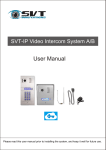
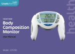
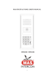
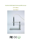
SVT-IP Video Intercom System B
User Manual
Please read this user manual prior to installing the system, and keep it well for future use.
CONTENTS
1. Parts and Functions............................................................................................. 1
2. Terminal Descriptions .......................................................................................... 1
3. Specification ...................................................................................................... 2
4. Mounting.............................................................................................................. 2
5.System Wiring and Connections.......................................................................... 3
5.1 System Wiring Diagram.................................................................................. 3
5.2 Electric Door Lock Connection ....................................................................... 4
6. Setup ................................................................................................................... 4
6.1 Wi-Fi Wireless Connection .................... ........................................................5
6.1.1 iPhone/iPad users ..................................................................................... 5
6.1.2 Android users ............................................................................................6
6.2 RJ45 Ethernet Cable Connection ................................................................. 7
6.3 How to add additional users to the SVT-IP Outdoor Station......................... 8
6.4 How to reset the SVT-IP Outdoor Station to factory default.......................... 8
7.System settings....................................................................................................9
8.User Guide (Control Cam App)........................................................................... 9
Talking/Unlocking the door/gate/Monitoring/Image Capture/Video Recording....9
How to delete a device/Change the unlock code...............................................10
9. Power Supply ...................................................................................................10
1.Parts and Functions
Rear View
Front View
Speaker
LED Light
Camera
Name Plate
RJ45
Call Button
Ethernet Cable
Antenna
Microphone
Doorbell
Exit Button
Power Supply
Electric Door Lock
2.Terminal Descriptions
-1-
Wi-Fi: Wireless connection.
Connect the antenna to enable Wi-Fi connection
RJ45: Ethernet cable connection.
Connect the Ethernet cable to a modem when
Wi-Fi is out of the range of your Wi-Fi network.
CN2:
1&2: Exit Button connection.
3, 4 & 5: Door Lock connection.
DOORBELL: External doorbell connection
POWER: Outdoor Station's power supply connection.
3.Specification
Max. 13V dc 1.4A
Must be used according to the lock.
01 – 99 seconds
-13°F to 149°F / -25°C to 65°C
4.Mounting
1
2
Plastic wall plug
Screws
System
Wiring
Rain Cover
160-165cm
-2-
3
4
1
2
5.System Wiring and Connections
5.1 System Wiring Diagram
-3-
5.2 Electric Door Lock Connection
1.
The external power supply must be used according to the lock.
2.
The door lock is limited to 13V, 1.4A.
3.
An Exit Button can be connected to CN2.
4.
We recommend soldering the wires together for better results.
6.Setup
Android users can download the ControlCam App directly from the Google Play Store,
and IOS users can download it from the Apple Store. Both download and usage are
free for SVT Innovations users.
>Download the ControlCam App, and install it in your smart phone or tablet.
>Ensure the Outdoor Station is in the range of your Wi-Fi network.
>Always keep the App updated to the latest version for proper functionality.
ControCam App herein subject to change without prior notice.
-4-
>There are two ways to connect the Outdoor Station to the network/router:
1. Wi-Fi wireless connection (Note that ControlCam App works with 2.4Ghz network)
2. RJ45 Ethernet cable connection
6.1 Wi-Fi Wireless Connection:
6.1.1. iPhone/iPad users:
Step 1: Once the ControlCam App is downloaded and installed, ensure your iPhone
or iPad is connected to the same Wi-Fi network as the one you are going to connect
the SVT-IP system;
Step 2: Attach the Antenna to the Wi-Fi pin on the back of the outdoor station;
Step 3: Open the ControlCam App, and select "Add a Device";
Step 4: Select "Add a New Device";
Step 5: Select "Start configuring";
Step 6: Select the outdoor station to be configured, then select "Start configuring"
again;
Step 7: Select the Wi-Fi network, input its password and then select "Setting";
Step 8: Input the default User Name (admin) and Password (1234), then select "OK"
to confirm;
Step 9: Go back to the device list and select "..." on the top right corner of the
screen, then select "ON" in the Outdoor call-in option.
Step 10: Return to the main interface. The setup is complete and ready to
receive calls and monitor the SVT-IP outdoor station.
-5-
6.1.2. Android users:
Step 1: Once the ControlCam App is downloaded and installed, ensure your
smart phone or tablet is connected to the same Wi-Fi network as the one you are
going to connect the SVT-IP system;
Step 2: Attach the Antenna to the Wi-Fi pin on the back of the outdoor station;
Step 3: Open the ControlCam App, and select "Enter Now";
Step 4: Select "Add a Device";
Step 5: Select "Add a New Device";
Step 6: The App will start searching for an online outdoor station;
(If not found, try it again and ensure the smart phone/tablet is in rage of the Wi-Fi network)
Step 7: Select the outdoor station to be configured, then select "Start configuring";
Step 8: Select the Wi-Fi network, input its password. The configuration starts
automatically and it takes 100 seconds to be completed;
Step 9: Once the configuration is completed, select "OK" to confirm;
Step 10: Input the default User Name (admin) and Password (1234), then select
"OK" to confirm;
Step 11: Go back to the device list and select "..." on the top right corner of the
screen, then select "ON" in the Outdoor call-in option.
Step 12: Return to the main interface. The setup is complete and ready to
receive calls and monitor the SVT-IP outdoor station.
-6-
6.2 RJ45 Ethernet Cable Connection
If you are installing the SVT-IP Outdoor Station in a place out of the range of your
Wi-Fi network, you may use the RJ45 Ethernet cable connection instead.
You must first connect it to the Wi-Fi network following the instructions on pages 5
or 6. Do not remove the antenna until the RJ45 Ethernet cable connection is
completed.
Step 1: Login to your router setting page to find the IP address and the Gateway of
the SVT-IP Outdoor Station.
Step 2: Open Internet Explorer on your pc and type the IP address into the Address
Bar to open the "IP Camera login page".
Step 3: Login using the same default user name (admin) and password (1234) as
the ControlCam App.
Step 4: Select "Config." - "Network Settings" - LAN, and set the IP address and
Gateway the same as your LAN network. Select "Save" to complete the new settings.
-7-
Step 5: You can now connect the RJ45 cable to the SVT-IP Outdoor Station and
then connect the Ethernet cable to the router.
Step 6: The setup is complete. You can now remove the antenna from the SVT-IP
Outdoor Station.
6.3 How to add additional users to the SVT-IP Outdoor Station:
Step 1: Open the ControlCam App, select "Enter Now";
Step 2: Select "Add a Network Device";
There are three ways to add additional users to the SVT-IP Outdoor Station:
a. LAN Search:
Select "LAN Search" and select the outdoor station that you would like to add.
Input the default user name and password, then select "Ok" to confirm.
b. QR Code Scan:
Select "QR Code Scan", input the default user name and password, then select
"OK" to confirm.
c. Manually Input:
Select "Manually Input", input the outdoor station's GID, then input the
default user name and password. Select "OK" to confirm.
Step 3: Select "..." on the top right corner of the screen;
Step 4: Select "ON" in the Outdoor call-in option. Return to the main interface. The
setup is complete and ready to receive calls and monitor the SVT-IP outdoor
station.
6.4 How to reset the SVT-IP Outdoor Station to factory default:
If the outdoor station has been previously connected to a Wi-Fi router, you must
first reset it to factory default prior to connecting it again to a new Wi-Fi router:
Step 1: Unplug the outdoor station from the power outlet.
Step 2: Power it back on
Step 3: Hold the call button for 45 seconds, until the LED light flashes and a "Bi..."
sound is heard.
-8-
7.System settings
The system settings can be reviewed and changed on the "IP Camera
configuration page.
To login, follow the steps 1 - 3 on page number 7.
Adjust the date and time: Select Config. - System - System time. You may
adjust the settings selecting NTP Server, Synchronize with local computer or set
the time manually.
Activate Motion Detection: Select Config. - Alarm Settings - Motion
Detection. Then select "Enable" , and save to confirm .
Note: The IP Camera configuration page offers advanced settings. Most settings
require professional network knowledge.
8.User Guide (ControlCamApp)
8.1 Talking:
When a guest presses the call button, the device will receive a ring alert. The user
can either accept or decline the call on the pop-up call alert box. Press and hold
to start talking and release to listen.
8.2 Unlocking the door/gate:
Input the unlock code while on monitoring or talking mode to release the door/gate
(Use the default system password as the unlock code).
8.3 Monitoring:
Select the outdoor station's image on the main interface to monitor your door/gate.
Press
to listen, or press
to start talking.
8.4 Image Capture:
Select
to capture an image of the outdoor station's camera.
8.5 Video Recording:
Select the icon
to start video recording; press the icon
to end the video
recording.
-9-
8.6 How to delete a device:
Step 1: Select "..." on the top right corner of the screen;
Step 2: Select "OFF" in the Outdoor call-in option;
Step 3: Select "Edit", then "Delete";
Step 4: Select "OK" to confirm the action and delete the device.
8.7 Change the unlock code:
Step 1: Select "..." on the top right corner of the screen;
Step 2: Select "OFF" in the Outdoor call-in option;
Step 3: Select "Unlock password setting";
Step 4: Input the old code, then input a new code;
Step 5: Select "Setting" to save the changes.
9. Power Supply
Name
SVT-IP
POWER SUPPLY
(IP14310)
Description
It supplies power for the outdoor station
only.
-10-
Specifications
Input Voltage: 100 ~ 240Vac Input
Frequency: 50 ~ 60Hz 0.6A
Output: DC 15V 1.5A
Working temperature: 14°F to 104°F /
-10°C to 40°C
The design and specifications of this user manual can be changed without any notification to the user.
All copyright and interpretation rights are reserved to SVT Innovations Inc.