1
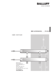
VM2 Load Cell Panel Meter User Manual (High Resolution)
ESC
SET
Main Display
HOLD
OUT1
OUT2
OUT3
OUT4
COMM
PEAK
ZERO
TEACH
Escape Key
(Comparing Setting)
Set Key
(Parameter Setting)
Up Key
ZO/TH
Secondary
Display
Ver : 1.12
Digit-shifting Key
(Scale Setting)
(Communication Setting)
Zero/ Teach Key
Status Lamp
Output Lamp
Function Introduction
Main Display
To display input weight at present or parameter items in setting mode.
Secondary Display To display Set Value in running mode or parameter values in setting
mode.
Button Introduction
ESC
To cancel settings or return to Main Display.
SET
To enter parameter setting mode or confirm settings.
To change value in setting mode or set scale value and decimal place.
To change the digit to set or change option items directly in setting mode.
+
+
Press for 1 sec. to clear Peak record.
ZO/TH
Press for 1 sec. to force zeroing.
ZO/TH
Press for 1 sec. to cancel forced zeroing.
Instruction of Operation & Setting
Main Display
SET
Target Setting
SET
Pre-warn Value
Main Display
SET
Upper Limit
ESC
High Limit
ESC
SET
ESC
SET
High Limit Setting
ESC
SET
Low Limit
SET
Low Limit Setting
ESC
ESC
SET
SET
Zero Setting
ESC
~ 1 ~
Lower Limit
ESC
Parameter List & Introduction
Item
Selecting Input
Filter
Display
Setting Range
20/40 mV
none / fast / normal /
slow / slowest
Function Introduction
To selecting the range of input signal.
To filter the surge and regular jitter of input signal.
Movable Average
1 ~ 16
To filter out noise, making display more stable.
Simple Average
1 ~ 16
To slow down the display to make it more stable.
Zero Time
General Setting
Zero Range
Display Scale
0 ~ 9.9 Sec
0 ~ 999
1/2/5/10/20
Tracking time of auto zeroing.
Auto zeroing range.
To set the minimum increasing grade of display value.
Input Limit
0 ~ 99999
Zero Mask
0 ~ 999
Display 0 if input signal is lower than set range.
Power Frequency
50/60 Hz
Please input corresponding work frequency according
to that of the domestic electricity.
The maximum software limit of input signal.
In-2 Function
Input function selection of control point
(see explanation below).
Input function selection of control point
(see explanation below).
Input Voltage
To view actual input voltage.
In-1 Function
Decimal Place
0.0000/0.000/0.00/0.0 Setting of decimal place of present value.
Scale Setting
Scale Mode
2 set/5 set
In-1 Value
-19999 ~ 99999
The input value corresponds with display ratio 1.
(Can be set through TEACH.)
Display 1 Value
-19999 ~ 99999
The display value corresponds with input ration 1.
In-2 Value
-19999 ~ 99999
The input value corresponds with display ratio 2.
(Can be set through TEACH.)
Display 2 Value
-19999 ~ 99999
The display value corresponds with input ration 2.
In-3 Value
-19999 ~ 99999
The input value corresponds with display ratio 3.
(Can be set through TEACH.)
Display 3 Value
-19999 ~ 99999
The display value corresponds with input ration 3.
In-4 Value
-19999 ~ 99999
The input value corresponds with display ratio 4.
(Can be set through TEACH.)
Display 4 Value
-19999 ~ 99999
The display value corresponds with input ration 4.
In-5 Value
-19999 ~ 99999
The input value corresponds with display ratio 5.
(Can be set through TEACH.)
Display 5 Value
-19999 ~ 99999
The display value corresponds with input ration 5.
Analog Output 1
-19999 ~ 99999
The displayed value corresponding to the minimum
of analog output.
The displayed value corresponding to the maximum
of analog output.
Analog Output 2
Comparing
Setting
Comparing
Mode
Comparing
Source
-19999 ~ 99999
Stand/Zone/Level/Peak
/Mode1/Mode2/Mode3
To set scale setting as 2 sets or 5 sets.
To select output comparing mode.
(See Output Explanation)
DISP/GROSS/PEAK/HOLD To select output comparing source.
Output 1
HH/HI/GO/LO/LL 5 output modes will be generated after the input signals
Output 2
HH/HI/GO/LO/LL of the modes. (Please see the explanation below.)
are compared. The output contact can correspond with any
~ 2 ~
Display
Output 3
Setting Range
HH/HI/GO/LO/LL
Output 4
HH/HI/GO/LO/LL
Item
Function Introduction
Comparing
Setting
5 output modes will be generated after the input signals are
compared with set values. The output contact can correspond
with any of the modes.(See explanation below.)
Communication
Setting of communication mode. Set according to
actual application.
For identifying data during communication. Can’t be
1 ~ 255
repeated in the same set.
Setting of Baud rate. The higher the speed, the lower
19200/9600/4800/2400/1200
the ability of noise susceptibility.
7O1/7E1/7N2/7O2/7E2/
Setting of communication format. Set according to
8N1/8O1/8E1/8N2
actual application.
Communication
Mode
Communication
ID
ASCII/RTU/STEAM
Baud Rate
Communication
Format
ON/OFF
Ending Character
Communication
Data
Communication
Delay
Add ending character in the end in STREAM mode.
DISP/GROSS/PEAK/HOLD Select sent data type in STREAM mode.
20 ~ 9999 ms
In STREAM mode, send delay time automatically.
Function Introduction of Input Control Contacts
Forced Zero: To force the input value to zero. Press Shift+UP key to cancel.
Tare: Set the input value to be deducted.
Display Gross Weight: The secondary display shows set value in operation and shows gross weight
when this function is enabled.
Lock Panel Keys: When this function is enabled, keys on the panel can’t be operated.
HOLD: When this function is enabled, displayed value won’t change, but the value will be recorded.
If comparative source is set as HOLD, then the meter will proceed comparing.
Display Peak Value: To switch the display of the secondary window to PEAK Value.
Display Peak Value: To switch the display of the secondary window to PEAK Value,
and clear PEAK record.
Peak Value Auto Capturing: The function needs to work when the comparative mode is set
as PEAK. Please see Output Mode Explanation.
Print: The function needs to work when the communication mode is set as STRAM. Output
data types (Display, Gross, Peak, Hold) are selectable. Data is sent once per operation.
No Function
Set Limit Superior
Set High Limit
Set Low Limit
Set Limit Inferior
Set Target Value
Set Preset Value
Set Zero Range
~ 3 ~
Communication Format Setting:
Protocol: Modbus RTU or ASCII, and Stream Mode
Address (ID): 1 ~ 255
Baud rate: 19200, 9600, 4800, 2400bps
Data Length: 7 & 8bit
Stop bit: 1 & 2bit
Parity check: None, Odd, Even
Stream Mode:
Stream Mode can be sent automatically or via external triggering. When the
input control is selected as “Print” function, it is via external triggering; otherwise,
it is automatic. The sending interval can set between 20 ~ 9999ms.
The sent data can be any of the following (including formats):
NET
XX.XXX
CR
LF
GROSS
XX.XXX
CR
LF
PEAK
XX.XXX
CR
LF
HOLD
XX.XXX
CR
LF
Setting of Communication Contact (ModBus Mode):
Item Format Add Modbus
Add
bit
0000 00001
01
Read/
Write
Description
W
To force to zero. (Repeatable)
02
bit
0001 00002
W
To clear the records of minimum and maximum.
1: clear records; 0: no operation
03
bit
0002 00003
R
OUT1 Status
04
bit
0003 00004
R
OUT2 Status
05
bit
0004 00005
R
OUT3 Status
06
bit
0005 00006
R
OUT4 Status
07
word
0000 40001
R/W Setting of the filter (None/Fast/Normal/Slow/Slowest)
08
word
0001 40002
R/W Movable average setting. Range: 1~16
09
word
0002 40003
R/W Simple average setting. Range: 1~16
10
word
0003 40004
R/W Setting of decimal place.
11
word
0004 40005
R/W Auto zeroing time. Range: 0~99 * 100 (ms)
12
word
0005 40006
R/W Auto zeroing range. Range: 0~9999
~ 4 ~
13
word
0006 40007
R/W Setting of display scale. 0=>1, 1=>2, 2=>5, 3=>10, 4=>20
14
word
0007 40008
R/W Setting of zero cut. Range: 0~999
15
word
0008 40009
R/W Frequency setting of electricity. 0=>60Hz, 1=>50Hz
16
word
0009 40010
R/W Setting of Input Control 1. Range: 0~13
17
word
000A 40011
R/W Setting of Input Control 2. Range: 0~13
18
word
000B 40012
R/W Setting of comparative mode. Range: 0~6
19
word
000C 40013
R/W Setting of comparative source. Range: 0~3
20
word
000D 40014
R
Output Status
21
dword 0032 40051
R
Present Value. Range: -19999 ~ 99999
22
dword 0034 40053
R
Value of gross weight. Range: -19999 ~ 99999
23
dword 0036 40055
R
Maximum value. Range: -19999 ~ 99999
24
dword 0038 40057
R
Hold Value. Range: -19999 ~ 99999
25
dword 003A 40059
R/W Set value of target. Range: 0 ~ 99999
26
dword 003C 40061
R/W Setting of preset value. Range: 0 ~ 99999
27
dword 003E 40063
R/W Setting of zero range. Range: 0 ~ 99999
28
dword 0040 40065
R/W
29
dword 0042 40067
R/W Set value of high limit. Range: 0 ~ 99999
30
dword 0044 40069
R/W Set value of High limit of the software. Range: 0 ~ 99999
29
dword 0046 40071
R/W Value of superior limit. Range: -19999 ~ 99999
30
dword 0048 40073
R/W Value of high limit. Range: -19999 ~ 99999
31
dword 004A 40075
R/W Value of low limit. Range: -19999 ~ 99999
32
dword 004C 40077
R/W Value of Inferior limit. Range: -19999 ~ 99999
33
dword 004E 40079
34
word
0050 40081
of display mode.
R/W Setting
0 => Display input signal; 1 => Display communication set value
35
word
0051 40082
36
word
0052 40083
of the decimal place of communication display value 1.
R/W Setting
Range: 0 ~ 4
of the decimal place of communication display value 2.
R/W Setting
Range: 0 ~ 4
37
dword 0053 40084
R/W Set value 1 of communication display. Range: -19999 ~ 99999
38
dword 0055 40086
R/W
R
Set value of superior limit. Range: 0 ~ 99999
Minimum value. Range: -19999 ~ 99999
Set value 2 of communication display. Range: -19999 ~ 99999
~ 5 ~
Comparing
Mode
0
1
2
Standard
Area
Level
Comparing
Source
Input Control
0
Display
0
Forced Zero
8
INHIBIT
INHIBIT
1
Total
1
9
Nil
Nil
2
Peak
2
Deduct Gross
Weight
Display Total
Weight
10
3
Hold
3
Key Lock
11
3
Peak Mode
4
Mode 1
4
Display Peak
12
5
Mode 2
5
Display Peak
13
6
Mode 3
6
Capture Peak
14
7
Print
15
~ 6 ~
Target Setting Setting of limit
superior
Preset Setting Setting of upper
limit
Upper Limit
Setting of lower
Setting
limit
Lower Limit
Setting of limit
Setting
inferior
Zero Setting
Comparative Output
STANDARD
ZONE
Metered Value
Metered Value
SP-HH
SP-HI
SP-LO
SP-LL
HH-OUT
HI-OUT
GO-OUT
LO-OUT
LL-OUT
LEVEL
SP-HH
SP-HI
SP-LO
SP-LL
ON
OFF
SP-HH
SP-HI
SP-LO
SP-LL
ON
OFF
HH-OUT
HI-OUT
GO-OUT
LO-OUT
LL-OUT
Output Mode (PEAK):
HH-OUT
HI-OUT
GO-OUT
LO-OUT
LL-OUT
Output Mode 1
PEAK
PEAK-Preset
Target Setting
Target Setting-Preset
SP-HI
SP-HI
SP-LO
SP-LO
Zero Setting
Zero Setting
OUT1
OUT2
OUT3
OUT4
OUT1
OUT2
OUT3
OUT4
Output Mode 2
Output Mode 3
Target Setting +SP-HI
SP-HI
Target Setting- SP-LO
SP-LO
Zero Setting
Zero Setting
OUT1
OUT2
OUT3
OUT4
OUT1
OUT2
OUT3
OUT4
~ 7 ~
Metered Value
ON
OFF
External Wiring
12
13
14
15
16
17
20
+Exc -Exc
22
9
Metered Value
SP-HH
SP-HI
SP-LO
SP-LL
18
19
HH-OUT
HI-OUT
GO-OUT
LO-OUT
LL-OUT
2 3 4 5
RS-485
21
8
OUT1
11
OUT2
10
OUT3
OUT4
Analog
Output
Output Setting
7
6
5
4
3
+Sig
-Sig
2
1
Output can be set to correspond with any of the output mode.
COM
Input1
Input2
AC/DC
100~240V
OUT1
Main Feature
Input Signal
Aux. Power
Frequency
Resolution
Max. Display
Accuracy
Display Size
Output Method
(Optional)
2/4.5 mV/V (Input Range:21mV/42mV)
5V/100 mA
60/50 Hz (Auto switch according to domestic electricity.)
500000 scale
-19999 ~ 99999
0.005% FS
0.56"(red), 0.3" (green)
Relay contact output: 1~3 sets (a,b), 4 sets (a)
Analog output: 4~20mA, 1~5V, 0~10V (12/16 bits)
Communication output: RS-232, RS-422, RS485(Modbus RTU/ASCII or Stream)
Rated Specification
Power Supply AC/DC 90 ~ 260V 50/60 Hz
Pwr Consumption Under 15VA
Insulation Impedance Above 20MΩ (DC 500V) (between terminal and housing, input and output)
AC 2000V 1 minute (between terminal and housing, input and output)
Hi-pot Test
Noise Susceptibility 2KV 5KHz
Ambient Temperature 0 ~ +50℃
Relative Humidity 25 ~ 85% RH (no condense)
Storage Temperature -20 ~ +65 ℃
Net Weight
330 grams
152(L) X 96(W) X 48(H) mm
Dimension
~ 8 ~
Model Explanation:
VM2
HLC
R - A
C
Index Output Contact (R) Analog Output (A) Communication (C)
0
-
-
-
1
-
4-20mA (12 bits)
RS-232
2
-
0-10V (12 bits)
RS-422
3
-
4-20mA (16bits)
RS-485
4
4 Relay
0-10V (16 bits)
-