1
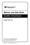
INSTALLATION GUIDE &
USER MANUAL
Sound Plus™ Infrared Listening System
Model WIR TX925, Two-Channel Listening System
Model WIR TX900, Four-Channel Listening System
Model WIR SYS 1, Two-Channel Listening System
Model WIR SYS 2, Two-Channel Listening System
Model WIR SYS 2P, Two-Channel Listening System
Model WIR SYS 4, Four-Channel Listening System
RoHS
Modulator Model MOD 232
Emitter Model WIR TX9
Optional Receiver Models WIR RX22-4, WIR RX14-2, WIR RX16
MAN 132C
SOUNDPLUS™ INFRARED LISTENING SYSTEM
INSTALLATION GUIDE AND USER MANUAL
Contents
Page
SYSTEM OVERVIEW . . . . . . . . . . . . . . . . . . . . . . . . . . . . . . . . . . . . . . . . . . . . . . . . . . . . . . . . . . . . . . . . .3
INSTALLATION PROCEDURES
• MOD 232 Modulator Setup . . . . . . . . . . . . . . . . . . . . . . . . . . . . . . . . . . . . . . . . . . . . . . . . . . . . . . . . . . .4
Wiring & Connections . . . . . . . . . . . . . . . . . . . . . . . . . . . . . . . . . . . . . . . . . . . . . . . . . . . . . . . .4
Features & Controls . . . . . . . . . . . . . . . . . . . . . . . . . . . . . . . . . . . . . . . . . . . . . . . . . . . . . . . . . .6
Configuration Settings . . . . . . . . . . . . . . . . . . . . . . . . . . . . . . . . . . . . . . . . . . . . . . . . . . . . . . . .7
• TX9 Emitter Setup . . . . . . . . . . . . . . . . . . . . . . . . . . . . . . . . . . . . . . . . . . . . . . . . . . . . . . . . . . . . . . . . . .8
Coverage Area . . . . . . . . . . . . . . . . . . . . . . . . . . . . . . . . . . . . . . . . . . . . . . . . . . . . . . . . . . . . . .9
Features & Controls . . . . . . . . . . . . . . . . . . . . . . . . . . . . . . . . . . . . . . . . . . . . . . . . . . . . . . . . .11
Mounting . . . . . . . . . . . . . . . . . . . . . . . . . . . . . . . . . . . . . . . . . . . . . . . . . . . . . . . . . . . . . . . . .11
• Receiver Safety Instructions . . . . . . . . . . . . . . . . . . . . . . . . . . . . . . . . . . . . . . . . . . . . . . . . . . . . . . . . .12
• Recycling Instructions . . . . . . . . . . . . . . . . . . . . . . . . . . . . . . . . . . . . . . . . . . . . . . . . . . . . . . . . . . . . . .12
• Optional Receivers . . . . . . . . . . . . . . . . . . . . . . . . . . . . . . . . . . . . . . . . . . . . . . . . . . . . . . . . . . . . . . . . .13
TROUBLESHOOTING . . . . . . . . . . . . . . . . . . . . . . . . . . . . . . . . . . . . . . . . . . . . . . . . . . . . . . . . . . . .14
WARRANTY
. . . . . . . . . . . . . . . . . . . . . . . . . . . . . . . . . . . . . . . . . . . . . . . . . . . . . . . . . . . . .15
SPECIFICATIONS
• MOD 232 Modulator . . . . . . . . . . . . . . . . . . . . . . . . . . . . . . . . . . . . . . . . . . . . . . . . . . . . . . . . . . . . . . .16
• Model TX9 Emitter . . . . . . . . . . . . . . . . . . . . . . . . . . . . . . . . . . . . . . . . . . . . . . . . . . . . . . . . . . . . . . . .17
2
SYSTEM OVERVIEW
The Williams Sound SoundPlus™ Infrared Listening System consists of a MOD 232 Modulator(s) and
one or more TX9 Emitters which use invisible infrared (IR) light to broadcast speech or music to
wireless infrared receivers.
The system is designed to transmit high quality audio for hearing assistance and language translation
applications. Because the system uses infrared light for transmission, it is not affected by interference
from radio equipment and does not interfere with radio equipment. No FCC license or radio approval
is required.
The system can be used with microphones as a stand-alone system, or can be connected to other
sound equipment. Infrared systems generally cannot be used in direct sunlight because of sunlight’s
large amount of interfering infrared light.
Note: This equipment has been tested and found to comply with the limits for a Class A
digital device, pursuant to part 15 of the FCC Rules. These limits are designed to provide
reasonable protection against harmful interference when the equipment is operated in a
commercial environment. This equipment generates, uses, and can radiate radio frequency
energy and, if not installed and used in accordance with the instruction manual, may cause
harmful interference to radio communications. Operation of this equipment in a residential
area is likely to cause harmful interference in which case the user will be required to correct
the interference at his own expense.
NOTICE: A PLASMA MONITOR CAN DEGRADE THE AUDIO QUALITY OF THE
SOUNDPLUS INFRARED LISTENING SYSTEM. FOR BEST PERFORMANCE, THE
SOUNDPLUS EMITTER SHOULD BE POSITIONED AS FAR AWAY FROM THE
PLASMA MONITOR AS POSSIBLE.
3
MOD 232 MODULATOR SETUP
DETERMINE LOCATION
The modulator is usually located with the sound system amplifier or mixer for easy access to an audio
input signal. For portable systems, the modulator can be placed near the emitter or in another convenient
location. Infrared Stand Kits (SS-6 and SS-11) are available for portable systems.
WIRING AND CONNECTIONS
Figure 1: MOD 232 (Rear View)
WARNING: POWERLINE VOLTAGE MUST NOT FALL BELOW 94V, OR
SYSTEM PERFORMANCE WILL BE GREATLY REDUCED!
POWER CONNECTION FOR U.S. APPLICATION
Step 1: Connect the TFP 016 power supply to the 3-pin MolexTM
connector located on the rear of the MOD 232.
(See Figure 2, right.)
FOR APPLICATIONS OUTSIDE THE U.S. REQUIRING 240 VAC MAINS SUPPLY:
Use the transformer power supply, model TFP 027.
Secondary specifications: 24 VAC, 35 VA, 50/60 Hz.
Step 2: Plug the power supply into the AC outlet.
TFP 027-01: 230VAC, Euro Mains Plug
TFP 027-02: 230VAC, UK Mains Plug
4
Figure 2:
Power Connection
BASEBAND CABLE CONNECTION
The MOD 232 can directly drive one or two emitters. TX9 emitters repeat the baseband signal, so any
number of emitters can be used. The modulator outputs CANNOT be split with CATV splitters.
Determine the length of RG-58 cable needed to reach from the TX9 Emitter to the Modulator unit.
Install BNC connectors to each end of the cable.
For two-channel operation, only one MOD 232 is required: Connect the coaxial cable to one of the
Baseband Output jacks on the rear of the MOD 232. The other end of the coaxial cable connects to the
Baseband Input jack of the TX9 Emitter. See Figure 3 below.
Figure 3: Baseband Connection, Two Channel Operation
Connect to the TX9 using RG-58 cable and BNC connectors. The MOD 232 has two baseband output
jacks to simplify connections when multiple emitters are used.
To setup a system for four-channel operation, two MOD 232 Modulators are required. Link the two
Modulator units together as shown in Figure 4. Connect the baseband output from the second modulator
in the chain to the TX9 emitter(s) baseband input connector.
Figure 4: Baseband Connection, Four Channel Operation
IMPORTANT: Each channel must be set to a different frequency!
5
AUDIO CONNECTION
MICROPHONE INPUT:
With the modulator DIP switches set for microphone
input, the 3-pin XLR jack accepts balanced
microphones. Power for condenser microphones can be
selected by DIP switch. The minimum input level is
100uV and the maximum level is 90 mV.
XLR LINE-LEVEL INPUT:
With the modulator DIP switches set for line-level
input, the 3-pin XLR jack accepts balanced line-level
audio inputs. The minimum input level is 21mV and
the maximum level is 10uV.
1/4” TRS LINE-LEVEL INPUT:
The 1/4” Tip/Ring/Sleeve (TRS) jack can accept only
a balanced or unbalanced line-level input.
A 25 V, 70 V, or 100 V speaker line can be connected to the
balanced line input using an appropriate attenuator. “T”
pads made with resistors yield better fidelity than speaker
matching transformers.
Figure 6: Features and Controls
6
Figure 5: Audio Connection
CONFIGURATION SETTINGS
Figure 8 illustrates how to configure your system using the DIP switches (Figure 7) on the back of the
MOD 232 Modulator. This diagram is also printed on top of the MOD 232 Modulator unit for quick
reference.
Figure 7: Configuration Switches
Adjust switch settings on rear of
MOD 232 Modulator here:
Figure 8
IMPORTANT: Channel A and Channel B must be set to different frequencies!
COMPRESSOR GAIN
The MOD 232’s Compressor Gain is set in “Moderate” mode from the factory. Use this setting for simultaneous
interpretation. Be sure that the compress control, located on the front of the MOD 232 (Figure 6, page 6), is turned fully
counter-clockwise. Compression can be added if desired by turning the compress control clockwise.
For hearing assistance applications, the MOD 232’s Compressor Gain can be set to “Maximum” mode. For additional
compression, use a tuning wand (PLT 005) or small screw driver and gently turn the compress control (Figure 6, page 6)
on the front of the MOD 232 clockwise.
7
TX9 EMITTER SETUP
TX9 LOCATION AND PLACEMENT
To determine the best location for the TX9 Emitter, it helps to think of the IR emitter as an invisible
floodlight. You’ll want to aim it so the listeners are “flooded” with the infrared light. Mount the emitter
at least 2 ft (.61 m) above the audience.
Position the emitter to face in a slightly downward angle - that will increase the “throw” of the infrared
beam. Infrared light reflects off most surfaces and scatters, increasing the coverage area. Rough surfaces
tend to absorb infrared light, minimizing reflections, and limiting coverage to the direct illumination.
Remember: opaque objects block infrared light. Thus, emitters cannot be concealed behind opaque
walls, curtains, etc.
The emitter front red plastic lens must NOT be painted. Neither should emitters be used in areas of
extreme high or low temperature, humidity, or chemical environments.
The TX9 Infrared Emitter should not be installed where there is a lot of direct sunlight, which can create
infrared interference.
Figure 9: 3 Dimension Foot Pattern
8
Figure 10: NOTE: When pointing
the emitter, be sure to keep the
long dimension horizontal.
COVERAGE AREA
Figure 11: Maximum Range when using the RX22-4, RX14-2, or RX16 receiver
RX16
RX14-2
RX22-4
These patterns are the direct radiation pattern. The infrared radiation does not drop to zero outside the
illustrated patterns; it decreases. It still may be useable at a greater distance, depending on the receiver
sensitivity and the reflective characteristics of the room. Reflections of the infrared light from walls,
ceilings, and floors may change these patterns.
9
MULTIPLE EMITTERS INSTALLED TO MAXIMIZE COVERAGE
Figure 12A
Figure 12A and !2B:
Overlapping Illumination
Patterns to Cover Larger
Listening Areas
Figure 12B
Figure 13: Connecting Multiple TX9 Emitters
An unlimited number of WIR TX9 emitters can be daisy-chained together to maximize the coverage
area. Remember that each emitter needs its own power supply and cannot share a power supply
with a modulator or another emitter.
10
TX9 FEATURES AND CONTROLS
Figure 14: TX9 Emitter Rear View
For use with mounting
bracket.
Is visible on bottom
MOUNTING THE TX9 TO A WALL OR CEILING
Figure 15: Mounting the TX9 to a wall, ceiling, or suspended ceiling with the BKT 024 using a
Mounting Plate or a T-Bar Clip
OR
11
RECEIVER SAFETY INFORMATION
HEARING SAFETY
CAUTION!
This product is designed to amplify sounds to a high volume level which could
potentially cause hearing damage if used improperly. To protect your hearing and the
hearing of others:
1.
Make sure the volume is turned down before putting on the earphone or headphone
before adjusting the volume to a comfortable level.
2.
Set the volume level at the minimum setting that you need to hear.
3.
If you experience feedback (a squealing or howling sound), reduce the volume setting
and move the microphone away from the earphone or headphone.
4.
Do not allow children or other unauthorized persons to have access to this product.
BATTERY SAFETY AND DISPOSAL
CAUTION!
This product is supplied with disposable Alkaline batteries. Do not attempt to recharge
disposable batteries, which may explode, release dangerous chemicals, cause burns, or other
serious harm to the user or product.
PACEMAKER SAFETY:
CAUTION!
1.
Before using this product with a pacemaker or other medical device, consult your
physician or the manufacturer of your pacemaker or other medical device.
2.
If you have a pacemaker or other medical device, make sure that you are using this
product in accordance with safety guidelines established by your physician or the
pacemaker manufacturer.
RECYCLING INSTRUCTIONS
BATTERY SAFETY AND DISPOSAL
Help Williams Sound protect the environment! Please take the time to dispose of your
equipment properly.
Product Recycling for Customers in the European Union:
Please do NOT dispose of your Williams Sound equipment in the household trash.
Please take the equipment to a electronics recycling center; OR return the product to
your Williams Sound dealer for proper disposal.
Battery Recycling for Customers in the European Union:
Please do NOT dispose of used batteries in the household trash. Please take the
batteries to a retail or community collection point for recycling.
10/01/07
12
OPTIONAL RECEIVERS
Figure 16: FOUR CHANNEL RECEIVER, MODEL WIR RX22-4
Channel
Frequency
1
2
3
4
2.3 MHz
2.8 MHz
3.3 MHz
3.8 MHz
Figure 17: WIR RX14-2 HEADSET RECEIVER
Figure 16: WIR RX16 UNDER-THE-CHIN RECEIVER
WIR RX16 Front View
13
TROUBLE SHOOTING
NEITHER TX9 INDICATOR LIGHT IS ON.
Make sure the transformer is plugged into the emitter and any remote power switch is on.
Make sure the electrical outlet is on.
Make sure the 24 VAC power supply is working.
ONLY TX9’S POWER INDICATOR LED COMES ON.
Make sure the MOD 232 is on.
Make sure the baseband cable is connected properly. See Figures 3 & 4.
Check to see if the carrier light on the MOD 232 is on.
Make sure an audio signal is being sent to the MOD 232.
NO SOUND THROUGH RECEIVERS.
If some of the receivers work but others don’t, check for bad batteries or earphones on the
receivers that aren’t working.
If none of the receivers work, check to see if the power and baseband cable are connected to the
emitter and that the TX9 Power and Baseband Present Indicator lights are ON.
Check to see if the modulator is connected properly to the sound system. The Frequency
Indicator should be lit and there should be activity on the MOD 232 Level Indicators.
Make sure the “eye” is not covered up on the receiver. There must be clear line of sight between
the receiver eye and the emitter panel.
SOUND THROUGH THE RECEIVERS IS WEAK AND NOISY.
Make sure each channel is set to a different frequency on the MOD 232 modulator. Listen to the
audio signal through the Phones jack of the MOD 232 modulator. You can also hold a receiver in
front of the Infrared Test LED on the front of the MOD 232 modulator and listen to the audio
signal. If the signal is weak and noisy here, check the Input Level switch and Input Level Control
settings. Increase the input signal level from the sound system by turning up the mixer control.
If the signal sounds okay, you may need to re-position the emitter panels or add additional panels.
NOTE: Make sure the powerline voltage does not fall below 94V, or system performance will be
greatly reduced!
BUZZING OR HUMMING NOISE IN SOUND SYSTEM.
14
Check for ground loops or noise on the input signal. Call your Authorized Williams Sound
dealer or representative.
LIMITED WARRANTY
Williams Sound products are engineered, designed, and manufactured under carefully controlled conditions to
provide you with many years of reliable service. Williams Sound warrants the SoundPlus™ Infrared Listening
System against defects in materials and workmanship for FIVE (5) years. During the first five years from the
purchase date, we will promptly repair or replace the SoundPlus™ Infrared Listening System.
Microphones, earphones, headphones, batteries, cables, carry cases, and all other accessory products carry a 90day warranty. Chargers carry a one year warranty.
WILLIAMS SOUND HAS NO CONTROL OVER THE CONDITIONS UNDER WHICH THIS PRODUCT IS
USED. WILLIAMS SOUND, THEREFORE, DISCLAIMS ALL WARRANTIES NOT SET FORTH ABOVE,
BOTH EXPRESS AND IMPLIED, WITH RESPECT TO THE SOUNDPLUS™ INFRARED LISTENING
SYSTEM, INCLUDING BUT NOT LIMITED TO, ANY IMPLIED WARRANTY OF MERCHANTABILITY OR
FITNESS FOR A PARTICULAR PURPOSE. WILLIAMS SOUND SHALL NOT BE LIABLE TO ANY
PERSON OR ENTITY FOR ANY MEDICAL EXPENSES OR ANY DIRECT, INCIDENTAL OR
CONSEQUENTIAL DAMAGES CAUSED BY ANY USE, DEFECT, FAILURE OR MALFUNCTIONING OF
THE PRODUCT, WHETHER A CLAIM FOR SUCH DAMAGES IS BASED UPON WARRANTY,
CONTRACT, TORT OR OTHERWISE. THE SOLE REMEDY FOR ANY DEFECT, FAILURE OR
MALFUNCTION OF THE PRODUCT IS REPLACEMENT OF THE PRODUCT. NO PERSON HAS ANY
AUTHORITY TO BIND WILLIAMS SOUND TO ANY REPRESENTATION OR WARRANTY WITH
RESPECT TO THE SOUNDPLUS™ INFRARED LISTENING SYSTEM. UNAUTHORIZED REPAIRS OR
MODIFICATIONS WILL VOID THE WARRANTY.
The exclusions and limitations set out above are not intended to, and should not be construed so as to contravene
mandatory provisions of applicable law. If any part or term of this Disclaimer of Warranty is held to be illegal,
unenforceable, or in conflict with applicable law by a court of competent jurisdiction, the validity of the remaining
portions of this Disclaimer of Warranty shall not be affected, and all rights and obligations shall be construed and
enforced as if this Limited Warranty did not contain the particular part or term held to be invalid.
If you experience difficulty with your system, call Toll-Free for customer Assistance:
1-800-843-3544 (U.S.A.) or +1 952 943 2252 (Outside the U.S.A.)
If it is necessary to return the system for service, your Customer Service Representative will give you a Return
Authorization Number (RA) and shipping instruction.
Pack the system carefully and send it to:
Williams Sound Corp.
Attn: Repair Dept.
10321 West 70th Street
Eden Prairie, MN 55344 USA
Your warranty becomes effective the date you purchase your system. Your returned warranty card is our way of
knowing when you warranty begins. Please take a moment to fill it out and mail the enclosed card. You may also
register your product online: www.williamssound.com/registration.aspx. This information will help us serve you
better in the future. Thank you!
15
SOUNDPLUS™ INFRARED LISTENING SYSTEM SPECIFICATIONS
MODELS WIR TX900, WIR TX925, WIR SYS 1, WIR SYS 2, WIR SYS 2P, WIR SYS 4
Two-Channel Modulator, Model MOD 232
Size, Weight:
Color:
Rack Mount:
Power Supply:
Modulation:
Carrier Frequency:
Signal to Noise Ratio:
Frequency Response:
Total Harmonic Distortion:
Audio Processing:
Auto Carrier Shut-Off:
Power Switch:
Power Indicator:
Audio Level Controls:
Audio Indicators:
Carrier LEDs:
Compress Control:
Input Mix LED:
Stereo LED:
Phones Switch:
Phones Output:
Infrared Test LED:
Power Input:
Audio Input Jack:
Mic Level:
Line Level:
Audio Line Output Jacks:
Configuration Switches:
Baseband Input Jack:
Baseband Output Jack:
Approvals:
Operating requirements:
Warranty:
8.5” W x 8.2” D x 1.7” H (21.5 cm x 20.8 cm x 4.4 cm), 3.1lbs. (1.5 kg)
Black epoxy paint with white legends
1/2 rack space wide, 1 rack space high, one or two modulators may be mounted in a
single IEC rack space with RPK 005 (single) or RPK 006 (double) Rack Mount Kits
Wall Transformer, 24VAC, 50-60 Hz, 15VA
North America:
TFP 016, UL/CSA
Europe:
TFP 027-01, 2-pin Schuko plug, CE
UK:
TFP 027-02, 3-pin UK plug, CE
FM Wideband, +50kHz deviation, 50uS pre-emphasis
Channel A: Selectable, 2.3/2.8/3.3/3.8MHz,
Channel B: Selectable, 2.3/2.8/3.3/3.8MHz
More than 60dB
30 to 16,000Hz, +1 dB, -3dB, electrical response
Less than 2%, electrical response
Compression (slope) adjustable from 1:1 to 4:1
Switchable compression gain: Moderate: 16dB. Max: 33dB
15 minute timer shuts off carrier when no audio is present (can be disabled)
Two-position push button, ON/OFF
Green LED
CHA and CHB Input Level, rotary knobs
CHA and CHB Audio Level, 10-segment LED’s
4 green LED carrier “on” indicators per channel (indicates frequency, malfunctions)
1:1 to 4:1
Indicates inputs A and B audio are mixed and transmitted by CHA. CHB off
Indicates stereo mode
Selects CH1 or CH2 for phones when not in stereo mode
1/4” TRS headphone jack. Accepts stereo, mono, and any impedance phones.
IR LED for receiver testing, monitoring, and audio signal testing.
3-Pin Molex, 24VAC, 50-60Hz, 15 VA
CHA and CHB combination XLR/TRS jack
Balanced, Lo-Z, 100µV min. to 90 mV max., 1mV nominal, 3kΩ input impedance,
supplies switchable simplex power per DIN 45596 for condenser mics
Balanced or unbalanced, 21mV min. to 10V max., 212mV nominal, 100kΩ
RCA Jack, CHA and CHB, 500mV, unbalanced, 100Ω source impedance, load
impedance must be greater than1kΩ
CHA and CHB 8-position DIP switch, selects Mic/Line input, compressor gain, simplex
power, discrete or mixed inputs, carrier frequency, channel disable, auto shut-off timer.
BNC, allows mixing with additional MOD 232 Modulator (4CH operation), 100mV,
50Ω input impedance, use with MOD 232, BNC, RG-58 Cable
Two BNC jacks carry baseband signal, 100mV/channel, 50Ω source impedance, for use
with WIR TX9 or MOD 232 only
CE, FCC, RoHS, WEEE
0-50º C ambient temperature, non-condensing, non-corrosive atmosphere
5 years on Modulator, 90 days on accessories
NOTE: SPECIFICATIONS SUBJECT TO CHANGE WITHOUT NOTICE.
16
Multi–Channel Infrared Emitter, Model TX9
Dimensions, Weight:
Color:
Power Supply:
Power Cable:
Indicators:
Carrier Frequency:
Emitter IR Power:
Coverage Area:
Baseband Input:
Baseband Output:
Baseband Cable:
Operating Requirements:
Mounting Kits:
Warranty:
Approvals:
Compatible Receivers:
11.25” W x 6.25” H x 2.125” D (28.6 cm x 15.9 cm x 5.4 cm), 1.9lbs (0.9 kg)
Black with white legends, red acrylic lens
Wall Transformer, 24VAC, 50-60Hz, 35VA, 3-pin MOLEX Connector
North America:
TFP 010, UL/CSA
Europe:
TFP 027-01, 2-pin Schuko plug, CE
UK:
TFP 027-02, 3-pin UK plug, CE
Note: Each WIR TX9 requires its own power supply
NEC Class 2 wiring, two-conductor, 18 ga., 200’ (61m) max. length
Green LED power indicator, red LED baseband indicator
50 kHz to 8 MHz
3.5 watts
28,000 ft2 (2,600 m2) in single-channel mode when using the RX22-4 Receiver
11,000 ft2 (1,000 m2) in four-channel mode when using the RX22-4 Receiver
3,500 ft2 (325 m2) in single channel mode when using the RX14-2 Receiver
3,063 ft2 (285 m2) in single channel mode when using the RX16 Receiver
(See coverage area diagrams)
BNC, 100 mV per carrier, 50Ω, for use with WIR TX9 or MOD 232 only
BNC, 50Ω, for use with TX9 only
RG 58 Coax, BNC connectors, maximum 1000’ (300m) length
0-50º C ambient temperature, non-condensing, non-corrosive atmosphere
Wall or Ceiling Mount: BKT 024 Omnidirectional mount, Mic Stand Kit: SS-11 or SS-6
5 years on Emitter, 90 days on accessories
CE, FCC, RoHS, WEEE
WIR RX22-4 Four Channel Receiver, WIR RX14-2 Two Channel Receiver, RX16 TwoChannel Receiver
NOTE: SPECIFICATIONS SUBJECT TO CHANGE WITHOUT NOTICE.
Visit our website for the latest specifications and publications: www.williamssound.com
17
© 2007, Williams Sound Corp. MAN 132C