1
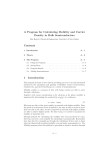
User’s Manual Model ISC40G(S) Sensors and Fittings for Inductive Conductivity Measurement IM 12D8J2-E-E 14th edition 2 IM 12D8J2-E-E 3 TABLE OF CONTENTS 1.INTRODUCTION............................................................................................................. 4 1-1.General...................................................................................................................... 4 1-2.Features.................................................................................................................... 4 1-3. CE declaration ISC40S.............................................................................................. 4 2.UNPACKING AND CHECKING..................................................................................... 5 3.WARRANTY AND SERVICE.......................................................................................... 5 4.GENERAL SPECIFICATIONS........................................................................................ 6 4-1.Model ISC40 Inductive conductivity sensor............................................................... 6 4.2.Model and suffix codes............................................................................................. 8 4.3.Dimensions of sensors............................................................................................ 10 4-4.Subassemblies, model ISC40FS.............................................................................. 11 4-5.Flow fitting, model ISC40FF..................................................................................... 12 4-6.Immersion fitting, model ISC40FD........................................................................... 13 5.INSTALLATION............................................................................................................. 14 5-1.Direct installation of sensor...................................................................................... 14 5-2.Installation of sensors with process adapters.......................................................... 15 5-3.Mounting the TF sensor........................................................................................... 16 5-4.Installation of subassemblies................................................................................... 18 5-5.Installation of flow fittings......................................................................................... 19 5-5-1. Installation of the sensor............................................................................... 19 5-5-2. Installation on wall, railing or stanchion......................................................... 19 5-5-3. Installation of the sanitary fitting.................................................................... 19 5-5-4. Installation in the process piping................................................................... 20 5-6. Installation of immersion fittings............................................................................... 20 5-6-1. Installation of the sensor............................................................................... 20 5-6-2. Installation on a railing or stanchion.............................................................. 20 6.SPARE PARTS............................................................................................................. 22 6-1.Options for ISC40 sensor as spare part................................................................... 22 6-2.Options for ISC40FF and ISC40FD as spare part.................................................... 22 6-3.O-ring spare parts for ISC40 sensor........................................................................ 23 6-4.Spare parts carrier and O-rings for the flow through sub-assemblies and fitting...... 23 6-5.O-rings for fittings ISC40FS and ISC40FS............................................................... 24 7.DIMENSIONS............................................................................................................... 25 IM 12D8J2-E-E 4 1. INTRODUCTION 1-1. General The sensor and fitting program for inductive conductivity measurement (model ISC40) is designed to meet the most common installation requirements in terms of material compatibility, process connections and flow dynamics. The various installation possibilities are described and illustrated in this manual. The following categories of installation can be recognised: 1. Direct mounting of sensors in tank wall or customer supplied flanges 2. Cost effective installation of sensors using process adapters 3. Maintenance friendly installation of sensors using in-line subassemblies 4. Installation in flow chambers for measurements in sample streams or bypass loops 5. Installation in immersion fittings for measurement in open tanks or channels 1-3. Sensors ISC40G(S)-GG Fig. 1-1. IM 12D8J2-E-E ISC40G(S)-GR 1-2. Features Within the wide range of process adapters, subassemblies, flow fittings and immersion fittings it is easy to find the appropriate installation that fits the application (a wide choice of materials), the plant installation practice (a wide choice of process connections) and the maintenance procedures. 1-3. CE declaration ISC40S The model ISC40S (the S indicates safety) is intended for use in potentially explosive atmospheres. A number of restrictions apply on the use of this sensor. Special conditions for safe use The sensor must be installed and used so, that dangers of ignition due to hazardous electrostatic charges cannot occur, especially in the case the process medium is non-conductive. Connection The sensor may only be connected to the transmitter models IC200S and ISC202S. Operation The sensor may only be used within it’s specified window of operation (chapter 4). ISC40G(S)-GS ISC40G(S)-TF 5 2. UNPACKING AND CHECKING Upon receipt of the goods, carefully inspect the shipping package for any evidence of damage. If the carton is damaged, notify the shipping agent and the sales organisation immediately. If the shipping package is not damaged, remove the products and parts. Confirm that all items shown on the packing list are available and that the package does not contain any parts or accessories hidden between the shock absorbing fillers. Notify the sales organisation if items are missing. 3. WARRANTY AND SERVICE Products and parts are warranted to be free from defects in workmanship and material under normal use and service for a period of typically twelve months from the date of shipment by manufacturer. The sales organisation has the possibility to deviate from this typical warranty period and the actual terms and conditions as specified in the sales order must be consulted. Damage caused by wear and tear, inadequate maintenance, corrosion and attack by chemical processes are excluded from this warranty coverage. All defective goods need to be sent to the service of the sales organisation for repair or replacement and the returned material should be accompanied by a letter of transmittal, which should include the following information: 2002 2003 2004 2005 2006 2007 2008 2009 2010 2011 2012 2013 P R S T U V W X A B C D January February March April May June July August September Oktober November December 1 2 3 4 5 6 7 8 9 O N D 1. P art number, model code and serial number 2. Date and number of sales order 3. Length of time of service and type of service 4. Description of the faulty operation of the device and the circumstances of the failure 5. Pressure, temperature, process composition and all other process conditions or environmental circumstances which are related to the installation and possibly failure of the device 6. Statement as to whether warranty or non-warranty service is requested 7. Complete shipping and billing instructions for return of material and name, phone number of contact person that can be approached for further information. The returned goods that have been in contact with process fluids must be detoxified and disinfected prior to shipment for the health and safety of our employees. Material Safety Data sheets must be included for all components of the processes in which the sensors/fittings have been used. The shipping address where to the goods have to be returned is specified on the original sales order or on the back page of this manual. IM 12D8J2-E-E 6 4. GENERAL SPECIFICATIONS 4-1. Model ISC40 Inductive conductivity sensor A. Compatibility :ISC40G is suitable for use with both ISC402G and ISC202G inductive conductivity transmitter. B. Hazardous area :ISC40S is suitable for use with the I(S)C202S conform to ATEX, FM and CSA intrinsic safety standards. - atex intrinsic safety : <Ex> ll 1 G EEx ia IIC T6 for ambient temp. -10 to 40°C <Ex> ll 1 G EEx ia IIC T4 for ambient temp. -10 to 55°C - atex certificate no. : KEMA 00 ATEX 1067 X - FM intrinsic safety :IS CL1, DIV1, GP ABCD T3B for ambient temp. (ta) -10°C to 55°C and T4 for ambient temp. (ta)-10°C to 40°C. - FM Approval report : J.I. 1Y1A7.AX - CSA intrinsic safety :Ex ia Class I, Division 1, Groups C and D, T4a - CSA Approval file : LR 102851-1 C. Measuring range : 0- 2000 mS/cm at actual process temperatures. The sensor has an error of 0.5 uS/cm (PEEK sensors) or 1 uS/cm (PFA sensor) that must be considered when application range is chosen. D. Installation factor :Cell constant: The nominal cell constant of the sensor is 1.88/cm-1 for the PEEK sensor types and 3.00/cm-1 for the PFA sensor. The calibrated values are indicated on the cable markers and the actual installation can change this factor. If there is less than 25 mm spacing between sensor and holder, in-situ calibration is necessary to meet the specified accuracies. Only for PEEK Correction factor (x nominal C.C.) 1.30 1.25 1.20 1.15 non conductive piping 1.10 D 1,05 1.00 0.95 conductive piping 0.90 0 10 D in millimeters 20 30 40 50 FIG. 2. A ctual installed cell-constant as function of spacing around the sensor. E. Process temperature range Peek : - 20 to 130°C (-4 to 266°F) for Response time 5 min. (90%) PFA : -20 to 100°C (-4 to 212°F) Response time 10 min. (90%) IM 12D8J2-E-E 7 F. Process pressure Peek :Maximum 20 bar (300 psi) dependant on installation. PFA : C (°F) 100 (212) 20 (36) BAR (PSI) 5 (71) 10 (142) G. Materials - Sensor wetted parts : ISC40G(S)-G•, Victrex PEEK (Poly-Ether-Ether-Ketone). 30% Glass filled PEEK. NOTE: This material is FDA approved. : PFA (high purity Perfluora Alkoxy Allcane) - Sealing gasket : Viton - Process adapters : AISI 316 SS, PVC or PVDF (only for PEEK) H. Process connection : Process connection are made in combination with a variety of adapters and fittings. See relevant sections in this document. In combination with all our process connections the ISC40 sensor meets IP67. When installed otherwise the sensor meets IP65. I.Cables - Connection cable - Extension cable J. Shipping details - Package - 3-5 meters - 10-20 meters - Packed weight approx. :Integral connection cable in a variety of lengths up to 20 meter. :Extension cable WF10 junction box BA10 can be used to a total of 50 metres (fixed cable and extension cable). : WxHxD = 350x270x50 mm : WxHxD = 320x240x110 mm - 03 m : 1.0 kg - 05 m : 1.3 kg - 10 m : 1.6 kg - 15 m : 2.1 kg - 20 m : 2.5 kg - protection hose 0.8 kg (approx.) IM 12D8J2-E-E 8 4-2. Model and suffix codes Model Suffix Option Description ISC40S Intrinsically safe inductive conductivity sensor Sensor type -GG Glass filled PEEK, general model -GRGlass filled PEEK, retractable model -GS Glass filled PEEK, shaft model -TF PFA, flange model Temperature -T1 Pt1000 sensor -T330k thermistor, for IC200 select only T3 Cable length -03 03 meter -05 05 meter -10 10 meter -15 15 meter -20 20 meter Option for sensor Material Process Connection Flange adapters -GG /SFA AISI316 SS 2” ANSI 150 lbs /SFD AISI316 SS NW50-PN16 /STW AISI316 SS 3” tri-clamp /S2W AISI316 SS 2” tri-clamp Flange adapters -GS /SFT AISI316 SS Sanitary Tuchenhagen /STC1 AISI316 SS Sanitary 2” tri-clamp /STC2 AISI316 SS Tri-clamp complete Protection Hose /PH 03m, 05m, 10m, 15m, 20m for -TF the same length as the cable Certificates /MMaterial certificate only for -GG, -GR /Q Quality certificate IM 12D8J2-E-E 9 Model Suffix Option Description ISC40G General purpose inductive conductivity sensor Sensor type -GG Glass filled PEEK, general model -GR Glass filled PEEK, retractable model -GS Glass filled PEEK, shaft model -TF PFA, flange model Temperature -T1 Pt1000 sensor -T3 30k thermistor, for IC200 select only T3 Cable length -03 03 meter -05 05 meter -10 10 meter -15 15 meter -20 20 meter Option for Sensor Material Process Connection Flange adapters -GG /SFA AISI316 SS 2” ANSI 150 lbs /SFD AISI316 SS NW50-PN16 /STW AISI316 SS 3” tri-clamp /S2W AISI316 SS 2” tri-clamp Flange adapters -GS /SFT AISI316 SS Sanitary Tuchenhagen /STC1 AISI316 SS Sanitary 2” tri-clamp /STC2 AISI316 SS Tri-clamp complete Protection Hose for -TF /PH 03m, 05m, 10m, 15m, 20m the same length as the cable Certificates /M Material certificate only for -GG, -GR /Q Quality certificate IM 12D8J2-E-E 10 4-3. Dimensions of sensors Unit: mm (inches) For mounting in ISC40PR retractable fitting nut G3/4 viton gasket 182 (7.16") 124 (4.88") Ø40 (1.57") 45 (1.77") Ø47 (1.85") Ø47 (1.85") Minimum hole to fit sensor through: Ø48 (1.89") Minimum hole to fit sensor through: Ø48 (1.89") ISC40G-GG ISC40G-GR ISC40-PR For mounting in SFT, STC 1 and STC 2 Fittings. G 3/4" Ø47 (1.85") Ø50 (1.97") IM 12D8J2-E-E ISC40G(S)-TF 189.5 (7.46") Minimum hole to fit sensor through: Ø50 (1.97") Minimum hole to fit sensor through: Ø48 (1.89") ISC40G-GS 124.5 (4.9") 77 (3.0") Peek Ø 100 (3.94) 193 (7.60") Stainless steel 56 (2.2") Ø 61 (2.4) Ø20 (0.78") 11 4-4. Subassemblies, Model ISC40FS Process temperature -Model ISC40FS-SCWN/SCSA -Model ISC40FS-PCSA -Model ISC40FS-FCSA Process pressure -Model ISC40FS-SCWN/SCSN -Model ISC40FS-PCSA -Model ISC40FS-FCSA : Max. 150°C (302°F). : Max. 100°C (212°F). : Max. 130°C (266°F). :Max. :Max. Max. :Max. Max. 1.0 0.6 0.1 1.0 0.1 MPa MPa MPa MPa MPa (150 psi) at 150°C (302°F). (90 psi) at 20°C (68°F). (15 psi) at 100°C (212°F). (150 psi) at 20°C (68°F). (15 psi) at 120°C (248°F). Wetted materials - Model ISC40FS-SCSA - Model ISC40FS-PCSA - Model ISC40FS-FCSA - All models : : : : Non-wetted materials - Nut : AISI 304 Stainless steel. AISI 316 Stainless steel Polypropylene PVDF (KYNAR) Viton O-ring. Process connection - Model ISC40FS-SCSA/PCSA/FCSA : 2” screw-in coupling Shipping details - Dimensions - Weight :Refer to section Drawings and Dimensions. : 500 g (1 lbs). Note: With the sensors, ISC40G-GG ISC40S-GG a gasket is supplied. This gasket maybe used for the older series of fittings. It should be discarded when the sensor is mounted in the following fittings : ISC40FS- FCSA, -PCSA. Model specifications Model Suffix code Option code Description ISC40FS Flow fitting subassembly Material -F PVDF -P Polypropylene -S Stainless Steel Process CS Coupling screw-in connection CW Coupling welded Thread type A NPT N No thread (for weld-in couplings) Options Material certificate /M 3.1 acc. EN 10 204 IM 12D8J2-E-E 12 4-5. Flow fitting, Model ISC40FF Process temperature - Model ISC40FF-S : Maximum 150°C (302°F). - Model ISC40FF-P : Maximum 100°C (212°F). - Model ISC40FF-F : Maximum 130°C (266°F). Process pressure - Model ISC40FF-S - Model ISC40FF-P - Model ISC40FF-F Wetted materials - Model ISC40FF-S - Model ISC40FF-P - Model ISC40FF-F - Process sealing : Max. 1.0 MPa (150 psi) at 150°C (302°F). : Max. 0.6 MPa (90 psi) at 20°C (68°F) : Max. 0.1 MPa (15 psi) at 100°C (212°F). : Max. 1.0 MPa (150 psi) at 20°C (68°F). : Max. 0.1 MPa (15 psi) at 120°C (228°F). : : : : AISI 316 Stainless steel Polypropylene PVDF (KYNAR) Viton O-ring. Non-wetted materials : AISI 304 stainless steel. Process connection : 1/2” NPT. - Optional adapters : See Model specifications. Note: W ith the sensors ISC40G-GG, ISC40S-GG a gasket is supplied. This gasket maybe used for the older series of fittings. It should be discarded when the sensor is mounted in the following fittings : ISC40FF-PA, -FA. Model specifications MODEL SUFFIX CODE OPTION CODE DESCRIPTION ISC40FF Flow fitting Material -S AISI 316 stainless steel -P Polypropylene (PP) -F PVDF (KYNAR®) Process connection A NPT Options 1/2”NPT Flang adapters /FF1 PVDF, DN15 PN10 /FF2 PVDF, DN25 PN10 /FF3 PVDF, ANSI 1/2”-150lbs /FF4 PVDF, ANSI 1”-150lbs /FP1 PP, DN15 PN10 /FP2 PP, DN25 PN10 /FP3 PP, ANSI 1/2”-150lbs /FP4 PP, ANSI 1”-150lbs /FS1 AISI 316 stainless steel, DN15 PN10 /FS2 AISI 316 stainless steel, DN25 PN10 /FS3 AISI 316 stainless steel, ANSI 1/2”- 150lbs /FS4 AISI 316 stainless steel, ANSI 1”- 150lbs Mounting set /MSWall/pipe for stainless steel flow fitting /MPWall/pipe for PP or PVDF flow fitting Material certificate only for -S‑ /M3.1 acc. EN-10-024 (DIN 50-049-3.1B) IM 12D8J2-E-E 13 4-6. Immersion fitting, Model ISC40FD Process temperature : Maximum 80°C (176°F). Process pressure : Maximum 0.2 MPa (30 psi) at 20°C (68°F). Wetted materials - Probe tube : C-PVC - Process sealing : Viton O-ring - Flange : PVC (optional) Non-wetted materials - Tube cable : Thermo plastic rubber Process connection : See Model specifications Note: W ith the sensors ISC40G-GG, ISC40S-GG a gasket is supplied. This gasket maybe used for the older series of fittings. It should be discarded when the sensor is mounted in the following fittings : ISC40FD-S, -V. Model specifications MODEL SUFFIX CODE OPTION CODE DESCRIPTION ISC40FD Immersion fitting Material -S Stainless Steel AISI 316 (SS) -V Polyvinylchloride (PVC) Pipe length -05 0.5 m -06 0.6 m -07 0.7 m -08 0.8 m -09 0.9 m -10 1.0 m -11 1.1 m -12 1.2 m -13 1.3 m -14 1.4 m -15 1.5 m -16 1.6 m -17 1.7 m -18 1.8 m -19 1.9 m -20 2.0 m Flange -SFD AISI316 SS NW50 -SFA AISI316 SS 2” -NFL No flange Options /MS1 pipe mounting set Only for ISC40FD-V /FAAdjustable, with DN50 PN10 and ANSI 2” 150 lbs hole pattern (only pvc) Only for ISC40FD-S /M 3.1 acc. EN-10-024 (only SS) Protection hose /PH5 For 5 m cable /PH10 For 10 m cable IM 12D8J2-E-E 14 5. INSTALLATION 5-1. Direct installation of sensor The ISC40 was previously supplied with a flat viton gasket for simple mounting. The fittings have been improved by the addition of “O”- ring seals which replace the flat gasket. We continue to supply the flat gasket with the ISC40G-GG, ISC40S-GG sensors for compatibility with existing installations. When using the sensor in combination with the new fittings, the flat gasket should be discarded. The mounting thread is a long straight G 3/4” thread (BSPP) which allows installation through a flange or bulkhead which may vary in thickness between 10 (3/8”) and 30 (1.2”) mm. The mounting hole in the flange or bulkhead must have a diameter of 27 mm (1.1”) to accommodate the mounting thread. The cable and mounting thread are pulled through this hole and the sensor is sealed from the process by tightening the mounting nut. Turning of the sensor by the torque forces can be avoided by using a wrench on the flats on top of the sensor. The flats are aligned with the flat sides of the donut (see fig.5-2). It is important that the process flow is directed through the hole in the donut. 1 2 PUSH & TURN 3 DO NOT WRENCH Fig. 5-1. Illustrates the mounting procedure. It is important that the access port has a diameter of at least 2” or 50 mm to allow insertion of the donut shaped end of the sensor (see fig. 5-3). The inductive conductivity measurement technique requires a process fluid surrounding the donut shaped sensor. The installation factor that is mentioned on the sensor will assure accurate conductivity measurement under the condition that the donut is surrounded by 25 mm (1”) process fluid. If this condition cannot be met in the actual installation, the analyser can be calibrated easily to assure a high accuracy in this application as well. Consult the paragraphs describing: “INSTALLATION FACTOR” and “ CALIBRATION” in the appropriate instruction manuals. IM 12D8J2-E-E A B Fig. 5-2. 15 5-2. Installation of sensors with process adapters The process adapters are standard blind flanges or male threaded blind plugs in which a hole of 27 mm is machined to accommodate the sensor. It is important that the flanges and weld-on sockets that have been provided by the enduser permit installation that meets the conditions as indicated in fig. 5-3. thermistor secondary primary ground wrench opening 20 ( 0.79 ) wrench opening 32 ( 1.42 ) YOKOGAWA G3/4 Ø 40 ( 1.57) Tight the nut securely on to the flange 47(1.85) Fig. 5-3. Sensor dimensions and cable numbering O-ring 26.57 x 3.53 d O-ring 40.64 x 5.33 D 26.57 x 3.53 116 (4.56) 40.64 x 5.33 D1 D2 H DIMENSIONS d /SFD Ø 18(0.71) /SFA Ø 19(0.75) DIMENSIONS D1 D2 material 125(5) 121(4.75) 165(6.5) 152(6.0) SS SS Fig. 5-4. Flange adapter I d D NOTE: During installation and de-installation of the threaded sensor adapters the mounting nut of the sensor must be loosened. Only in that case it is prevented that the sensor turns with the adapter with possible damage to the cable connection by torquing forces. FLANGE ADAPTER t 100 (3.94) ca 240 (9.45) 40 (1.57) The mounting of the sensor in the process adapter is described in section 5-1. The mounting of the process adapters in end-users installation requires compatibility of materials and process connections (see section 4). The dimensions that are important for the installation of the sensor adapters are noted in fig. 5-4. for flange adapters and in fig. 5-5. for threaded adapters. 11 12 17 13 15 16 14 L= 5000 ( 200 ) /SSG /PSG d D1 D2 material R2 R2 64(2.5) 75(3) 39(1.5) 42(1.7) SS PVC Fig. 5-5. Thread adapter IM 12D8J2-E-E 16 5-3. Mounting the TF sensor The PFA sensor top is marked with an arrow, which indicates the flat (upstream) face of the sensor. This should be aligned with the flow direction of the pipe. d 62 (2.45") D1 D2 t 2" ANSI/JIS 50 mm DIN 90 mm max. (3.50") D Fig 5-6. The PFA sensor is provided with a lapjoint flange of 100 mm diameter. This fits in standard flanged entry ports in the size range 2-3” or 50-80 mm, with the use of a suitable backing flange. The customer will normally supply this flange to match his local piping specifications. The preferred mounting flange will be made from a blind flange to match the installed pipework, with a clearance hole of 62 mm (2.45”). This flange serves to support the sensor as well as to locate it centrally in the pipe stub. Caution: When considering the use of the sensor with 2” or 50 mm lined pipe stub, take care to check the internal diameter of the lined pipe. The width of the sensor torroid at its widest point is 48 mm. This should pass through the smallest section and into the larger pipe for effective measurement. IM 12D8J2-E-E f f = distance min 25 mm (1") D = acces port size min 51 mm (2") Fig 5-7. Please note that with a flanged pipe mounting, the system should be calibrated by grab sample to set up the correct installation factor (taking account of the effect from the pipe walls). 17 3" ANSI/JIS 80 mm DIN With a standard 80mm/3” T-piece or branch the sensor will sit in the side arm. This will normally present no problem, as turbulence will refresh the solution surrounding the sensor, ensuring that the measurement remains valid. (see fig.5-8.) D Fig 5-8. OK OK OK OK Not recommended (solid deposits) Not recommended (air entrapment) Fig. 5-9. Installations examples of the ISC40-TF sensor IM 12D8J2-E-E 18 5-4. Installation of subassemblies The key difference between a sensor adapter and a subassembly is, that with subassembly installation the sensor can be removed from the process installation without removing the subassembly first. This allows easier access to the sensor for maintenance activities. Generally, the subassembly consists of three parts of which one part is fitted permanently to the process installation; the second part is fitted to the sensor and the third part holds the earlier parts together. In addition to these three parts there are elas-tomeric seals where appropriate. Dependent on the type of subassembly the permanent part is welded or threaded to the process installation. In figure 5-10 an illustration is given for a welding type subassembly versus a threaded model. ISC40FS-SCSA: supplied with O-ring ISC40FS-SCSA NOTE: Installation of the subassembly must fulfill the same dimensional requirements as described in § 5-1. Therefore specific attention is asked for the dimensional specifications of the subassemblies (see section 7). The assembly of the sensor in the subassembly is shown in the exploded view in fig. 5-10. ISC40FS-SCWN: suppied with O-ring ISC40FS-SCWN: Fig. 5-10. IM 12D8J2-E-E 19 5-5. Installation of flow fittings Installation of the flow fittings involves three steps: 5-5-1. Installation of the sensor Fig 5-11 shows how the sensor is mounted onto the sensor holding plate. It is important that the position of the sensor in the fitting allows easy flow through the hole in the sensor. Generally good flow is assured if the flats of the sensor are oriented perpendicular to the outlet piping. 5-5-2. Installation on wall, railing or stanchion For this purpose the flow fitting has an optional pipe/wall mounting kit. This kit consists of a clamp ring with bolts and nuts which clamps around the flow chamber. Therefore the flow chamber can be turned in the mounting assembly allowing for more flexibility in installation. Fig. 5-11. Part of the fitting is a mounting plate which can be mounted on a wall or panel with 2- 4 anchor bolts with a diameter of 10 mm (3/8”) max. plastic nut Nut tube For those installations where pipe mounting is requested, a saddle and U-bolt is supplied which allows mounting on a 2” nominal pipe size either horizontal or vertical. nut ring O-ring 18.7 x 2.6 For dimensions see section 7. Tuchenhagen Flange 5-5-3. Installation of the sanitary fitting Screw the tube completely in the stainless steel nut. Thread the sensor cable through parts in the right sequence. Screw the tube handtight into the flange (note: a mechanical stop will be felt). Tighten the plastic nut onto the sensor. Screw the plastic nut completely tight. Tighten the lock nut. The installation of this part is illustrated in figure 5-12. Check the O-ring ø 60 x 3 for correct mounting. ISC40G(S)-GS Fig. 5-12. IM 12D8J2-E-E 20 5-5-4. Installation in the process piping Basically the fittings have 1/2” threaded holes for process connection (NPT 1/2” or R1/2 dependent on model). The orientation of these holes is illustrated in the dimensional drawings, see section 7. SS In these pictures is also indicated the face to face dimensions of the optional process flange adapters. These flanges are either DN25 PN10 ; or ANSI 1” 150# dependent on model. NOTES: 1.It is important that the sample piping is oriented in such a way that the direction of the flow is upward to assure complete filling of the flow chamber. 2.When stainless steel flow chambers are used the analyser must be recalibrated as indicated in the instruction manual under “INSTALLATION FACTOR”. 5-6. Installation of immersion fittings For installation of the immersion fittings follow the two steps below: Fig. 5-13. 5-6-1. Installation of the sensor The exploded view in figure 5-13 shows the mounting of the sensor in the Stainless Steel and PVC fittings. 5-6-2. Installation on a railing or stanchion The immersion fitting comes with the optional rail mounting kit for mounting on vertical stanchion. This kit consists of a piece of guide pipe and two pipe clamps. The guide pipe is mounted horizontally to the stanchion using one pipe clamp. The second pipe clamp connects the guide pipe to the immersion fitting. The distance between the pipe clamps determines the distance between stanchion and immersion fitting. The positioning of the pipe clamp on the immersion fitting determines the immersion depth of the sensor. This is illustrated in figure 5-14. IM 12D8J2-E-E Fig. 5-14. PVC 21 Alternative ways of mounting the immersion fitting are: 1. Guide pipe The top of the immersion fitting has a larger diameter than the shaft to facilitate this type of mounting An user supplied 50 mm or 2” Nominal Diameter Schedule 40 guide pipe is fitted to the wall or to the mounting rail. The immersion fitting slides into the guide pipe easily and therefore the sensor can be easily removed from the channel for inspection. 2. Flange mounting The immersion fittings can be ordered with mounting flanges according to DN50 PN10; ANSI 2” 150# dimensions. You must be assured that the mating flange has the same hole pattern as the supplied flange. The pressure specifications of the mounting flange are not necessarily the same specifications as the immersion fitting. The specifications of the fitting are described in the specification section. An example of flange mounting is illustrated in figure 5-15, where the Polypropylene compression type adjustable flange is shown, which is optionally available for the PVC-C version immersion fittings. The flange can be compressed on any position of the fitting to allow exact insertion depth of the sensor. 3.Platform mounting Sometimes there is a walking platform that can be used to mount the immersion fitting. The top of the immersion fitting has a larger diameter than the shaft to facilitate this type of mounting. If it is possible to drill an precise hole of 51 mm (2”) in the platform, sliding the fitting through the hole is all is needed. Normally this is not possible in the expanded metal type. Then it is possible to use a blind flange to support the fitting in which a 51 mm (2”) hole is drilled. Guide pipe Ø 48,6 x 600 (Ø1.9 x 24") Min: 110 (4.35") Max: 515 (20") 2-inch Stanchion (Vertical) Fig. 5-15. ISC40FD - - - /MS1 IM 12D8J2-E-E 22 6. SPARE PARTS 6-1. Options ISC40 sensor as spare parts Option Description Material Process connection /SFA Flange adapter AISI316 SS 2” ANSI 150 lbs /SFD Flange adapter AISI316 SS DN50 PN16 /PSG Screw-in adapter PVC ISO 7/1-R2 /SSG Screw-in adapterAISI316 SS ISO 7/1-R2 /SFT Flange adapter AISI316 SS Sanitary Tuchenhagen /STC1 Flange adapter AISI316 SS Sanitary 2” tri-clamp /STC2 Flange adapter AISI316 SS Tri-clamp complete All adapters include Viton O-ring (s) /PH03 03 m protection hose /PH05 05 m protection hose /PH10 10 m protectionhose /PH15 15 m protectionhose /PH20 20 m protection hose Stainless Steel mounting nut for sensor Part number. K1541ZR K1541ZQ K1541ZN K1541ZL K1541ZP K1541ZG K1541ZF K1500DN K1500DP K1500DQ K1500DR K1500DS K1500AL (3pcs) 6.2. Options ISC40FF and ISC40FD as spare parts ISC40FF-.A Option /FF1 /FF2 /FF3 /FF4 /FP1 /FP2 /FP3 /FP4 /FS1 /FS2 /FS3 /FS4 Description Flange adapter Flange adapter Flange adapter Flange adapter Flange adapter Flange adapter Flange adapter Flange adapter Flange adapter Flange adapter Flange adapter Flange adapter Material PVDF PVDF PVDF PVDF PP PP PP PP AISI 316 SS AISI 316 SS AISI 316 SS AISI 316 SS Process connection DN15 PN10 DN25 PN10 ANSI 1/2”- 150lbs ANSI 1”- 150lbs DN15 PN10 DN25 PN10 ANSI 1/2”- 150lbs ANSI 1”- 150lbs DN15 PN10 DN25 PN10 ANSI 1/2”- 150lbs ANSI 1”- 150lbs Part number K1521AL K1521AP K1521AE K1521AH K1521AM K1521AQ K1521AF K1521AJ K1521AK K1521AN K1521AD K1521AG Option Description Material Process connection /MS1Pipe mounting set Carbon steel /FA Adjustable flange DIN DN50 PN10 ANSI 2” 150 lbs hole pattern (only for PVC) /PH5 Protection hose for 5 m cable /PH10 Protection hose for 10 m cable Part number K1541ZY K1520EV ISC40FD IM 12D8J2-E-E K1500CJ K1500CK 23 6-3. O - rings spare parts for ISC40 sensor O-ring material Dimensions EPDM Viton Silicon KALREZ Quantity O- rings for option FFJ5 /FSJ /PFJ /PSG /SFA SFD /SFJ /SSG / 40.64 x 5.33 / 26.57 x 3. 53 K1500CA K1500CB K1500CC 5 sets of 2 O-rings 40.64 x 5.33 K1500CD 1 O-ring 26.57 x 3. 53 K1500CH 1 O-ring O- rings for option /SFT 8.72 x 2.62 / 60 x 3 K1500CM K1500CL K1500CN 5 sets of 2 O-rings O- ring for option /STC1 18.72 x 2.62 K1500CQ K1500CP K1500CR 5 O-rings O- rings for option /STC2 18.72 x 2.72 / 2” clamp seal K1500CT K1500CS K1500CU 5 sets of 2 O-rings O- rings for protection hose 25.9 x 3.53 / 23.52 x 1.78 K1500DT 5 sets of 2 O- rings O- rings for old models Viton gasket K1500AM 5 O-rings O- rings for model ISC40FF-S 40.64 x 5.33 / 26.57 x 3.53 K1500DB K1500DA K1500DC 5 sets of 3 O-rings Ring NW50 40.64 x 5.33 K1500CD 1 O-ring 26.57 x 3.53 K1500CH 1 O-ring 53.34 x 5.33 K1500DD 1 O-ring O- ring for old model ISC40FF-S ring NW25 / ring NW50 K1541ZJ 2 sets of 2 O-rings Viton gasket K1500AM 5 O-rings O- ring for model ISC40FF-F and ISC40FF-P 40.64 x 5.33 / 26.57 x 3.53 K1500DF K1500DE K1500DG 5 sets of 3 O-rings 56.52 x 5.33 40.64 x 5.33 K1500CD 1 O-ring 26.57 x 3.53 K1500CH 1 O-ring 56.52 x 5.33 K1500DH 1 O-ring O- ring for old model ISC40FF-F and ISC40FF-P Viton gasket K1500AM 5 O-rings 56.52 x 5.33 K1541ZM 5 O-rings 6.4. S pare part sensor carriers and O-rings for the flow through sub assemblies and fittings Part no. K1541KC K1541KB K1541KD K1541KL K1541KA Description 2” tri-clamp carrier incl. 2 O - rings 3” tri-clamp carrier incl. 2 O - rings 2” carrier incl. 2 O - rings 2” carrier incl. 2 O - rings 2” carrier incl. 2 O - rings Material AISI 316 Stainless steel AISI 316 Stainless steel PVDF Polypropylene AISI 316 Stainless steel O - ring EPDM EPDM Viton Viton Viton IM 12D8J2-E-E 24 6-5. O - rings spare parts for sensor ISC40FD and ISC40FS Dimensions EPDM Viton O-ring material Silicon KALREZ O- rings for model ISC40FD-S 39.35 x 2.62 / 26.57 x 3.53 K1500CE K1500CF K1500CG 39.35 x 2.62 K1500CV 26.57 x 3.53 K1500CH O- rings for model ISC40FD-V 39.35 x 2.62 / 26.57 x 3.53 K1500CX K1500CW K1500CY 44.17 X 1,78 O- rings for old model ISC40FD-V 44.17 X 1,78 K1541ZS O- rings for model ISC40FS /PSCJ /PCSA /FCSJ /FSCA 40.64 x 5.33 / 26.57 x 3.53 K1500DF K1500DE K1500DG 56.52 x 5.33 40.64 x 5.33 K1500CD 26.57 x 3.53 K1500CH 56.52 x 5.33 K1500DH O- rings for model ISC40FS /SCSJ /SCSA /SCWN 40.64 x 5.33 / 26.57 x 3.53 K1500DB K1500DA K1500DC Ring NW50 40.64 x 5.33 K1500CD 26.57 x 3.53 K1500CH 53.34 x 5.33 K1500DD O- rings for model ISC40FS /S2WN 40.87 x 3.53 / 26.57 x 2.62 K1541ZH K1500DJ K1500DK 2” seal-clamp O- rings for model ISC40FS /STWN 40.87 x 3.53 / 26.57 x 2. 62 K1541ZK K1500DL K1500DM 3” seal-clamp O- rings for old model ISC40 PCSJ /PCSA /FSCJ /FSCA 56.52 x 5.33 K1541ZM O- rings for old model ISC40 SCSJ /SCSA /SCWN NW25 / NW50 K1541ZJ O- rings for old model ISC40 FD and FS Viton gasket K1500AM IM 12D8J2-E-E Quantity 5 sets of 2 O - rings 1 O-ring 1 O-ring 5 sets of 3 O - rings 5 O-rings 5 sets of 3 O - rings 1 O-ring 1 O-ring 1 O-ring 5 sets of 3 O - rings 1 O-ring 1 O-ring 1 O-ring 2 sets of 3 O-rings 2 sets of 3 O-rings 5 O-rings 2 sets of 2 O - rings 5 O-rings 25 7. DIMENSIONS SS L= 5000 ( 200 ) 11 12 17 13 15 16 14 ø60 (2.5) 42 (1.65) PVC ø50 (2) wrench opening 32 ( 1.42 ) L Ø 23,5 ( 0.92 ) 58 (2.28 ) wrench opening 20 ( 0.79 ) Ø 27 ( 1.06 ) 125 (5) 124 (4.88 ) Ø 40 ( 1.57) 16,3 ( 0.64 ) 47 ( 1.85 ) Fig. 7-1. Sensor Fig. 7-2. Immersion fittings Pipe/wall mounting kit 70 (2.75) 70 (2.75) Ø 10 (0.4) 4x pipe mount (vertical) pipe mount (horizontal) Fig. 7-3. Pipe/wall mounting kit IM 12D8J2-E-E 127 (5) 186 (7.32) d 26 L2 Option ø 90 (3.55) L1 L2 d /FF1 156 (6.14) 211 (8.31) 65 (2.56) /FF2 145 (5.71) 200 (7.87) 85 (3.35) /FF3 156 (6,14) 211 (8,31) 60,5 (2.38) /FF4 145 (5,71) 200 (7,87) 79,2 (3.12) /FP1 156 (6,14) 211 (8,31) 65 (2.56) /FP2 145 (5,71) 200 (7,87) 85 (3.35) /FP3 156 (6,14) 211 (8,31) 60,5 (2.38) /FP4 145 (5,71) 200 (7,87) 79,2 (3.12) L1 58 (2.3) d 158 (6.22) Fig. 7-4. Flow fittings PP/PVDF 39 (1.6) Option Direction of FLOW Flow direction Ø 54 (2.12) 120 (4.72) L1 Fig. 7-5. Flow fittings SS IM 12D8J2-E-E L1 d /FS1 260 (10.24) 65 (2.56) /FS2 280 (11.02) 85 (3.35) /FS3 260 (10.24) 60,5 (2.38) /FS4 280 (11.02) 79,2 (3.12) 27 Rd 78 x 1/6 acc. DIN 405 Rd 78 x 1/6 acc. DIN 405 Rd 78 x 1/6 acc. DIN 405 2" NPT acc. ANSI B.20.1 88 (3.46) 64 (2.52) 64 (2.52) Ø 50 /SCWN 2" NPT acc. ANSI B.20.1 Ø 50 /SCSA Ø 50 /PCSA /FCSA Fig. 7-6. IM 12D8J2-E-E 28 Chemical Compatibility Chart OOX - - - - - - OOO OOO XX OOO OOO - - - - - - OOO OOO OOO XXX XXX OOO OOO OOO - - OOO OOO OOO OOO OOO OOO OOO OOO OOX OOO X - OOO - - XXX OOO 20 60 100 OOO OOO OOO OOO OOO PFA 20 60 XXX XXX XXX - - - - - - XXX XXX OOO OOO - - XXX OOO - - - - OOX OOX XXX OOO OOO OOO OOO OOO XXX XXX - - OOO OOO XXX OOO XXX XXX XXX - - OOO XXX OOO XXX OOO OOO OOO OOX OOO PVC 20 60 OOO OOO OX - - OOO OOO OOX OOX OX - - OOO OOO OOO OOO OOO OOO OX OOO OOO OOO OOX OOX OOO OOO OOO OOO OOO OOO OOO OOO OOO OOO OOO OOO OOO OOO OOO OX OOX OOX OOO XXX OOO PP 20 60 100 10 50 95 fuming Hydrochloric acid 10 sat. Nitric acid 25 50 95 fuming Phosphoric acid 25 50 95 Hydrofluoric acid 40 75 Acetic acid 10 glacial Formic acid 80 Citric acid 50 Calcium hydroxide sat. Potassium hydroxide 50 Sodium hydroxide 40 Ammonia in water 30 sat. Ammonium chloride Zinc chloride 50 Iron (III) chloride 50 Sodium sulfite sat. Sodium carbonate sat. Potassium chloride sat. Sodium sulfate sat. Calcium chloride sat. Sodium chloride sat. Sodium nitrate 50 Aluminium chloride sat. Hydrogen peroxide 30 Sodium hypochloride 50 Potassium dichromate sat. Chlorinated lime Ethanol 80 Cyclohexane Toluene Trichloroethane Water 20 60 100 Organic solvent Oxidizing agent Neutral salt Basic Acid salt salt Alkali Organic acid Inorganic acid Sulfiric acid VITON 20 60 100 Temp. ºC % Conc. PVDF S.S. 316 (Kynar) 20 60 100 Material PEEK OOO OOX - - - - OOX OOX OOO XXX - - - - OOO OOO OOO - - - - OOO OOX XXX OOO OOO OOO OOO OOO OOO OOO OOO OOO OOO OOO OOO OOO OOO OOO OOO OOO OOO OOO XXX OOO OOO OOO OOO OOO OO OO X - OO OO OO X - - OO OO OO OO OO OO OX OO OO OO OO OO OO OO OO OO OO OO OO OO OO OO OO OO OO XX OO - OO - X - OO OX OO XX - OX OO OX OX - - OX OO OO OX XX OX XX OOO OO OO OX OX OO OO OO OO OO OO OO OO OO OO OO OO XX OO OO OX OO - - OO OOO OOO OOO OOO OOO OOO OOO OOO OOO OOO OOO OOO OOO OOO OOO OOO OOO OOX OOO OOO OOO OOO OOO OOO OOO OOO OOO OOO OOO OOO OOO OOO OOO OOO OOO OOO OOO OOO OOO OOO OOO OOO OOO O = can be used, O==shortens can beuseful used,life, X -X==cannot be used shortens useful life, Note: Information in this list is based on our general experience and literature data and given in good faith. - = cannot be used However Yokogawa is unable to accept responsobility for Note: Information in this list is based on our general experience and literature data and given in good faith. claims related to this information. However Yokogawa is unable to accept responsobility for claims related to this information. IM 12D8J2-E-E 29 IM 12D8J2-E-E 30 IM 12D8J2-E-E 31 IM 12D8J2-E-E YOKOGAWA ELECTRIC CORPORATION World Headquarters 9-32, Nakacho 2-chome, Musashino-shi Tokyo 180-8750 Japan www.yokogawa.com YOKOGAWA ELECTRIC ASIA Pte. LTD. 5 Bedok South Road Singapore 469270 Singapore www.yokogawa.com/sg YOKOGAWA CORPORATION OF AMERICA 2 Dart Road Newnan GA 30265 USA www.yokogawa.com/us YOKOGAWA CHINA CO. LTD. 3F Tower D Cartelo Crocodile Building No.568 West Tianshan Road Changing District Shanghai, China www.yokogawa.com/cn YOKOGAWA EUROPE BV Euroweg 2 3825 HD AMERSFOORT The Netherlands www.yokogawa.com/eu YOKOGAWA MIDDLE EAST B.S.C.(c) P.O. Box 10070, Manama Building 577, Road 2516, Busaiteen 225 Muharraq, Bahrain www.yokogawa.com/bh IM 12X0X0-E-E Subject to change without notice Copyright © IM 12D8J2-E-E Subject to change without notice Copyright © Yokogawa has an extensive sales and distribution network. Please refer to the European website (www.yokogawa.com/eu) to contact your nearest representative. Printed in The Netherlands, 00-000 (A) I 14-1210 (A) I Printed in The Netherlands