1
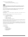
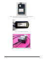
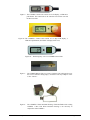
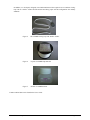
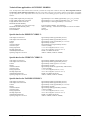
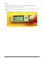
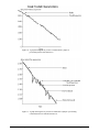
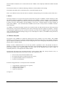
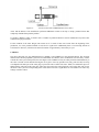
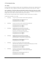
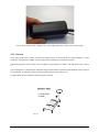
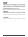
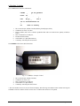
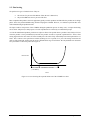
Airtec GmbH
CYPRES and CYPRES 2
Design and Test Report
All Models
in accordance with:
PIA TS-120: AAD Design and Testing Report Format
Test report begins with chapter 3
TS120cV3b
Document Revisions
Date
Changes
Document Revision
03/24/04
Minor changes:
Added ‘>’ to activation speeds in ‘Technical Data’ section for both CYPRES 1 and CYPRES
2.
Changed verbiage from ‘maint. Soon’ to ‘next maint. In’ for Section 3.5 item 7
Changed description in Section 4.3 from ‘was the diameter of a cigarette’ to ‘is
approximately one-half the size of a cigarette.
CYPRES 2 documentation
Initial Formal Release
Revision 1
Pre-Release
TS120cV3b
1/8/04
10/24/97
2/21/97
08/2/96
CYPRES TS-120 Report
24 March 2004
TS120cV3a
TS120cV2
TS120cV1
TS120c
Page i
This page intentionally left blank
CYPRES TS-120 Report
24 March 2004
Page ii
Table of Contents
1. OBJECTIVE............................................................................................................................................................ 1
2. REFERENCE DOCUMENTS ............................................................................................................................... 1
3. DESIGN DESCRIPTION....................................................................................................................................... 2
3.1. SPECIFIC USAGE MODES OF THE DEVICE ............................................................................................................. 2
3.2. PRINCIPLE OF OPERATION .................................................................................................................................. 3
3.3. TECHNICAL DATA .............................................................................................................................................. 7
3.4. LIMITATIONS ................................................................................................................................................... 10
3.5. PREVENTIVE MEANS OF THE DEVICE TO MINIMIZE THE AFFECTS OF SYSTEM OR SUB SYSTEM FAILURES ........... 10
4. TESTING ............................................................................................................................................................... 12
4.1. GENERAL OVERVIEW OF THE TESTING PROGRAM ............................................................................................. 12
4.2. ALTITUDE MEASUREMENT SUBSYSTEM............................................................................................................ 15
4.3. RELEASE SUBSYSTEM ...................................................................................................................................... 16
4.4. COMPLETE SYSTEM TEST ................................................................................................................................. 18
4.4.1. Installation and Function....................................................................................................................... 18
4.4.2. Drop Tests.............................................................................................................................................. 18
4.4.3. Live jumps .............................................................................................................................................. 19
4.5. ENVIRONMENTAL TESTING ............................................................................................................................. 20
4.5.1. Shock...................................................................................................................................................... 20
4.5.2. Vibration ................................................................................................................................................ 22
4.5.3. Humidity ................................................................................................................................................ 24
4.5.4. Salt ......................................................................................................................................................... 26
4.5.5. Temperature........................................................................................................................................... 27
4.5.6. Software ................................................................................................................................................. 27
4.5.7. EMI / EMS / ESD ................................................................................................................................... 28
4.5.8. Aging test for the CYPRES unit.............................................................................................................. 28
4.5.9. Other ...................................................................................................................................................... 29
5. HUMAN INTERFACE......................................................................................................................................... 30
5.1. ARM/DISARM .................................................................................................................................................. 30
5.2. USER CALIBRATION......................................................................................................................................... 30
5.3. PARAMETER CHANGES ..................................................................................................................................... 30
6. MARKING / LABELING .................................................................................................................................... 31
7. DOCUMENTATION ............................................................................................................................................ 33
8. MAINTENANCE .................................................................................................................................................. 34
8.1. FIELD MAINTENANCE ....................................................................................................................................... 34
8.2. MANUFACTURER MAINTENANCE ..................................................................................................................... 34
8.3. SERVICE STATIONS .......................................................................................................................................... 34
9. QUALITY CONTROL PROCEDURES/SYSTEMS AND METHODOLOGY ............................................. 35
9.1. PURCHASED PARTS / COMPONENTS .................................................................................................................. 35
9.2. PRODUCTION ................................................................................................................................................... 35
9.3. FINAL TESTING ................................................................................................................................................ 36
9.4. IN THE FIELD .................................................................................................................................................... 37
10. ADDITIONAL REMARKS ............................................................................................................................... 37
CYPRES TS-120 Report
24 March 2004
Page iii
This page intentionally left blank
CYPRES TS-120 Report
24 March 2004
Page iv
1. Objective
The PIA AAD Design & Testing Report Format is regarded as fulfilled when the manufacturer releases the
following test report about his product.
With the following report procedure, every manufacturer has their own choice to define the extent and kind of
requirements concerning their particular unit. The requirement regarding quality of each product results from
the self-defined test requirements. Each manufacturer is free to decide which of the actual tests and quality
control parameters they want to use in the published test report.
The self-chosen quality requirements should be documented.
The form of the description should follow a general format. In each section, the manufacturer should describe:
- the goal of the test, e.g. recognizing of the correct activation altitude, checking of correct function
under elevated temperatures, etc.
- how many units have been utilized to perform the test in question
- the test arrangement
- what has been measured/tested?
- how has it been measured/tested?
- what test equipment has been utilized?
Each test report shall contain references to all sections, even if they are “not recommended”. All sections
should be listed even when no data is presented. In this case a statement such as “not applicable”, “not
recommended”, “not appropriate”, “not valid”, or “no statement on this point” should be included. In the event
there is no reference to any particular section, the Para NewsBrief Editor will include the missing section with
the notation “no statement supplied by the manufacturer” prior to publishing the report.
2. Reference documents
MIL-STD-810E
Environmental Test Methods
MIL-STD-45662A
Calibration System Requirements
RTCA/DO-160C
Environmental Conditions and Test Procedures
MIL-STD-331B
Procedure C1 for Temp. & Humidity Test
RTCA/DO-178B
Software considerations in Airborne Systems and Equipment Certifications
MIL-STD-461D
Requirements of the Control of Electromagnetic Interference, Emissions and
Susceptibility
MIL-STD-331B
Appendix F Electrostatic Discharge (ESD)
CYPRES TS-120 Report
24 March 2004
Page 1
3. Design description
3.1. Specific usage modes of the device
Airtec developed the CYPRES for:
• experienced skydivers (Expert model),
• beginners and students (Student model),
• tandem operation (Tandem model),
• military freefall personnel, HAHO, and HALO (Military Model),
• smoke-jumper and other custom versions,
• water jumps (with usage of optional Water Resistant Housing),
• Emergency / Air Crew parachutes.
The Expert CYPRES is suitable for:
• style,
• accuracy,
• RW,
• CRW,
• freestyle,
• skysurfing,
• freeflying,
• static/line students,*
• AFF students and/or jumpmasters.
The Student CYPRES is suitable for:
• Static/line students,
• AFF students.
The Expert CYPRES, the Student CYPRES and the Tandem CYPRES are not suitable for:
• low-altitude jumps, (1500 feet AGL for the Expert/Student CYPRES and 3000 feet for the Tandem
CYPRES.)
• BASE jumping.
The MILITARY CYPRES is suitable for:
• HAHO, HALO,
• all EXPERT CYPRES and TANDEM CYPRES applications and for:
• wide altitude range adjustment,
• usage in widest temperature ranges,
• multiple event activation (i.e. drogue release before reserve activation),
• special applications like material drop.
All above listed CYPRES versions keep their qualities when the CYPRES Water Resistant Housing is installed. In
addition they are water-resistant for 15 minutes up to a depth of 5m / 15 ft.
* usage of Expert CYPRES for static/line students may be a compromise and may not necessarily reflect the best
possible device for the student’s security. It should, therefore, be reserved for special applications.
CYPRES TS-120 Report
24 March 2004
Page 2
The Emergency / Air Crew CYPRES is suitable for:
• Pilots, navigator and other aircraft crew member.
• Load master, oxygen technician and others working on an open ramp.
CYPRES 2
During the years 2000 through 2003 Airtec developed the CYPRES 2 in its civilian and military version based on
the design of CYPRES 1. Although more modern components were used and ergonomic aspects were improved, the
core design was not modified. Specifically, the activation parameter of the different versions and the software
algorythm are the same.
The above mentioned specific usage area for the different CYPRES versions are therefore all valid for CYPRES 2.
The only exception is the need for a water-resistant kit can be dropped: all versions of CYPRES 2 except the
Emergency / Air Crew CYPRES 2 are waterproof in their standard delivery form.
3.2. Principle of operation
The CYPRES initiates the reserve-container opening when a jumper descends to a specific altitude, in excess of a
specific descent rate.
Airtec designed the CYPRES around a highly accurate pressure-sensing device, and a data processor.
The processor can determine when a jumper is:
• at a constant altitude (on the ground),
• in an ascending or descending aircraft,
• in freefall,
• in a belly-to-earth orientation,
• in a back-to-earth orientation,
• tumbling, (either controlled or uncontrolled), etc.
The data processor evaluates the jumper’s altitude and descent-rate along with five other parameters. When ALL
SEVEN parameters indicate that an activation is necessary, then the CYPRES activates the Release Unit that severs the
reserve-container closing-loop, allowing the reserve-canopy to deploy.
The Release Unit is an electrically activated, piston/cylinder device. A knife-blade shape is machined into one end of the
piston. When an electrical current is applied to the Release Unit, the propellant product forces the piston through the
cylinder. When the knife-blade end of the piston reaches the reserve-container closing-loop, the knife-blade severs the
loop, initiating the reserve-canopy deployment sequence.
3.3. Technical data
The CYPRES consists of:
1. Processing Unit
2. Control Unit
3. one or two Release Units
4. optional water resistant housing
5. closing-loop and washer
6. special closing-loop material
7. closing-loop silicon
CYPRES TS-120 Report
24 March 2004
Page 3
Figure 1: The CYPRES Processing Unit containing the battery, the pressuremeasurement system and the processing electronics.
Figure 1a: The CYPRES 2 Processing Unit
Figure 1b:
CYPRES TS-120 Report
The Emergency / Air Crew CYPRES Processing Unit
24 March 2004
Page 4
Figure 2: The CYPRES Control Unit consists of a LCD display, a LED and a
push-button. The control unit is the interface between the user and
the Processor Unit.
Figure 2a: The CYPRES 2 Control Unit consists of a 5 digit LCD display, a
LED and a push-button (Ser.Numb. in display in this case).
Figure 2b: The Emergency / Air Crew CYPRES Control Unit
Figure 3:
The CYPRES Release Unit (or “Cutter”). Release Unit is designed to sever
the reserve-container closing-loop(s). A Release Unit may comprise of one
or two “Cutters.”
Figure 4:
The CYPRES 1 Water Resistant Housing. Field retrofitable with existing
CYPRES 1 units. This Water Resistant Housing is not necessary in
conjunction with CYPRES 2.
CYPRES TS-120 Report
24 March 2004
Page 5
In addition, we developed, designed, tested and manufactured the required reserve-container closingloop with its' "Smilie” washer and silicon lubricant. Many people call this configuration "the industry
standard."
Figure 5:
The CYPRES closing-loop and “Smilie” washer.
Figure 6:
A spool of CYPRES loop-material
Figure 7:
A bottle of CYPRES silicon.
Further technical data can be found in the User's Guide.
CYPRES TS-120 Report
24 March 2004
Page 6
Technical Data applicable to all CYPRES 1 MODELS:
Note: All temperature limits marked with an asterisk (*) indicate the temperature within the unit itself. These temperature limits do
not mean the outside (ambient) temperatures. Therefore, these limits won't have any meaning until the unit itself has reached that
specific temperature. These temperature limits rarely occur due to the insulating properties of the nylon pocket and its installation
location.
approximately 88 x 57 x 28.5mm (approximately 31/2 x 21/4 x 11/8 inch)
approximately 65 x 18 x 6.5mm (approximately 21/2 x 3/4 x 1/4 inch)
approximately 43 x 8mm (approximately 15/8 x 3/8 inch)
up to 98% relative humidity, non-condensing
14 hours
approximately 1.5% a year
after 4 years
Length, width, height of the processing unit
Length, width, height of the control unit
Length, diameter of the release unit
Maximum allowable humidity
Functioning period
Self-discharge rate of battery when stored at 20°C
First maintenance
Special data for the EXPERT CYPRES 1:
Cable length of control unit
Cable length of the release unit
Volume
Weight
Activation altitude
Activation speed
Storing temperature
Working temperature
Altitude adjustment limits
Operating range above sea level
Battery life
approximately 670mm (approximately 26 inch)
approximately 500mm (approximately 20 inch)
approximately 165cm³ (approximately 10 cu. inch)
approximately 262 gram
approximately 225 m (approximately 750 feet)
> 35m/sec (78mph)
+71° to -25° centigrade (160° F to -13° F)
+63° to -20° centigrade * (145° F to -4° F *)
±500m or ±1500ft from take-off.
-500m to +8000m (-1600ft to +26000ft)
maximum. 500 jumps or maximum. 2 years
Special data for the STUDENT CYPRES 1:
Cable length of control unit
Cable length of the release unit
Volume
Weight
Activation altitude
Activation speed
Storing temperature
Working temperature
Altitude adjustment limits
Operating range above sea level
Battery life
CYPRES TS-120 Report
approximately 1000mm (approximately 39 inch)
approximately 500mm (approximately 20 inch)
approximately 170cm³ (approx. 10.37 cu. inch)
approximately 279 gram
approximately 225 m (approximately 750 feet)
> 13m/sec (29mph)
+71° to -25° centigrade (160° F to -13° F)
+63° to -20° centigrade * (145° F to -4° F *)
±500m or ±1500ft from take-off
-500m to +8000m (-1600ft to +26000ft)
maximum. 500 jumps or maximum. 2 years
24 March 2004
Page 7
Special data for the TANDEM CYPRES 1:
Cable length of control unit
Cable length of the release unit
Volume
Weight
Activation altitude
Activation speed
Storing temperature
Working temperature
Altitude adjustment limits
Operating range above sea level
Battery life
approximately 670mm (approximately 26 inch)
approximately 500mm (approximately 20 inch)
approximately 165cm³ (approximately 10 cu. inch)
approximately 262 gram
approximately 580m (approximately 1900 feet)
> 35m/sec (78mph)
+71° to -25° centigrade (160° F to -13° F)
+63° to -20° centigrade * (145° F to -4° F *)
±500m or ±1500ft from take-off
-500m to +8000m (-1600ft to +26000ft)
maximum. 500 jumps or maximum. 2 years
Data for the WATER RESISTANT HOUSING (CYPRES 1 only):
retrofit
watertight
delivery
CYPRES TS-120 Report
Field retrofitable to most existing CYPRES 1 units. All units need
to be made watertight for the 1st time at Airtec or SSK.
Up to 15 minutes and down to 5 meters / 15 feet
The CYPRES Water Resistant Kit contains all necessary parts
including all tools and accessories for preparing a CYPRES unit
to be water resistant and ready for use including watertight
performance testing.
24 March 2004
Page 8
Technical Data applicable to all CYPRES 2 MODELS:
Note: All temperature limits marked with an asterisk (*) indicate the temperature within the unit itself. These temperature limits do
not mean the outside (ambient) temperatures. Therefore, these limits won't have any meaning until the unit itself has reached that
specific temperature. These temperature limits rarely occur due to the insulating properties of the nylon pocket and its installation
location.
approximately 85 x 43 x 32mm (approximately 31/3 x 12/3 x 11/3 inch)
approximately 65 x 18 x 6.5mm (approximately 21/2 x 3/4 x 1/4 inch)
approximately 43 x 8mm (approximately 15/8 x 3/8 inch)
Length, width, height of the processing unit
Length, width, height of the control unit
Length, diameter of the release unit
Maximum allowable humidity
(Emergency / Air Crew version only)
Maximum allowable humidity (other)
Functioning period
First maintenance
up to 98% relative humidity, non-condensing
100% (condensing) – water resistant at a depth of 15 feet for 15 minutes
14 hours
after 4 years
Special data for the EXPERT CYPRES 2:
Cable length of control unit
Cable length of the release unit
Volume
Weight
Activation altitude
Activation speed
Storing temperature
Working temperature
Altitude adjustment limits
Operating range above sea level
approximately 670mm (approximately 26 inch)
approximately 500mm (approximately 20 inch)
approximately 139cm³ (approximately 8 ½ cu. inch)
approximately 182 gram
approximately 225 m (approximately 750 feet)
> 35m/sec (78mph)
+71° to -25° centigrade (160° F to -13° F)
+63° to -20° centigrade * (145° F to -4° F *)
±500m or ±1500ft from take-off.
-500m to +8000m (-1600ft to +26000ft)
Special data for the STUDENT CYPRES 2:
Cable length of control unit
Cable length of the release unit
Volume
Weight
Activation altitude
Activation speed
Storing temperature
Working temperature
Altitude adjustment limits
Operating range above sea level
approximately 1000mm (approximately 39 inch)
approximately 500mm (approximately 20 inch)
approximately 144cm³ (approx. 8 ¾ cu. inch)
approximately 199 gram
approximately 300/225 m (approximately 1000/750 feet)
> 13m/sec (29mph)
+71° to -25° centigrade (160° F to -13° F)
+63° to -20° centigrade * (145° F to -4° F *)
±500m or ±1500ft from take-off
-500m to +8000m (-1600ft to +26000ft)
Special data for the TANDEM CYPRES 2:
Cable length of control unit
Cable length of the release unit
Volume
Weight
Activation altitude
Activation speed
Storing temperature
Working temperature
Altitude adjustment limits
Operating range above sea level
CYPRES TS-120 Report
approximately 670mm (approximately 26 inch)
approximately 500mm (approximately 20 inch)
approximately 139cm³ (approximately 8 ½ cu. inch)
approximately 182 gram
approximately 580m (approximately 1900 feet)
> 35m/sec (78mph)
+71° to -25° centigrade (160° F to -13° F)
+63° to -20° centigrade * (145° F to -4° F *)
±500m or ±1500ft from take-off
-500m to +8000m (-1600ft to +26000ft)
24 March 2004
Page 9
3.4. Limitations
The CYPRES is not suitable for:
•
•
•
low-altitude jumps, (1500 feet AGL for the Expert/Student CYPRES and 3000 feet for the Tandem
CYPRES.),
BASE jumping,
water jumps (without our optional water-resistant kit).
The sport CYPRES is equipped with a feature that allows the jumper to compensate for a difference between the
airport’s elevation and the drop-zone’s elevation. This difference is limited to plus/minus 1500 feet. The sport
CYPRES is limited to a maximum operational altitude of 26,000 MSL. The sport CYPRES can be used in a pressurized
aircraft, however the cabin-pressure must never exceed that of the ground-pressure.
3.5. Preventive means of the device to minimize the affects of system or sub system failures
The CYPRES always performs a “self-test” when a jumper switches-on the unit. The processor analyses its own
functionality, then the rest of the entire Processor Unit. It continues by checking the Release Unit (cutter), as well as the
battery.
The self-test checks for capability of functioning, respectively within the limits, among other things, for the following:
1.)
2.)
3.)
4.)
5.)
6.)
Battery cable with and without load.
Functioning of the computer subsystems.
Integrity of the cutter subsystems.
Functioning of the pressure measuring device subsystems.
Stability of the measure environment.
Calibration on the ground pressure.
The limits of this check were chosen such, that the functioning can be guaranteed for the next 14 hours.
If the processor detects any errors, it displays a number on the Control Unit. The number indicates an error-code. The
jumper can compare the error-code to a list in the User’s Manual. If the processor detects a serious error, the processor
activates a self-locking mechanism. The self-locking mechanism completely prevents the jumper from switching-on the
CYPRES. The CYPRES unit must be removed from the parachute system and must be sent to the manufacturer for
servicing.
CYPRES TS-120 Report
24 March 2004
Page 10
CYPRES 2
In addition to the self-test functions described in Chapter 3.5 the CYPRES 2 performs the following test:
7.) Verification if the device is due for scheduled factory maintenance
In CYPRES 2, maintenance schedule is not notified by an error code but with a clear text sentence (“next maint. in” or
“maint now”).
Fig. 8: Example of “Next Maintenance in” indication in the CYPRES 2 display.
CYPRES TS-120 Report
24 March 2004
Page 11
4. Testing
4.1. General overview of the testing program
Airtec researched numerous techniques for measuring a skydiver’s altitude. Some of the techniques were:
• RADAR or SONAR systems,
• gyroscopic navigation (with acceleration-measurement in three dimensions),
• air-pressure measurement,
• GPS based position measurements.
Airtec researched all of these methods and built functional prototypes utilizing three of these techniques before deciding
that the air-pressure measurement system was the most practical.
Development
We investigated if, in the real-environment of skydiving, our intended concept would function.
First, we designed, built and used pressure measurement devices to measure pressures in different skydiving activities
and skydiving-related situations.
Then we designed and built “data-collection units”, equipped with data-memory. The data-collection units produced
pressure data-logs for the various environments in which a jumper could be exposed. These environments are:
on the ground,
inside the aircraft,
on exit,
freefall,
canopy deployment,
under canopy,
on landing,
under water.
We collected air-pressure data by performing many jumps while carrying the data-collection units. We determined and
understood the extent of air-pressure “fluctuations”, caused by airflow variations around a jumper’s body while the
jumper is in the different skydiving environments.
During the first development we entered an area, for which there was no literature or information existing at the time.
Consequently we measured and recorded the pressure during the course of the entire jump:
- On the ground before boarding.
- In the aircraft before the propellers started rotating.
- In the aircraft while the propellers are rotating.
- During the taxiing.
- During take off.
- During climbing and on the run jump.
- On exit.
- During the entire freefall.
- On canopy opening.
- Under canopy.
- On landing.
CYPRES TS-120 Report
24 March 2004
Page 12
Measurements of the above targets were done for all existing jump disciplines in 1988/1990, such as:
- Accuracy
- Style
- Relative
- Canopy Relative
- Freestyle
and in addition:
- Stable Freefall
- Unstable, e.g. Tumbling Freefall
Since 1990 Airtec has never stopped investigating new jump disciplines. Some of the areas of importance in this regard
are:
-
Jumps with fixed and fabric wings (Birdman suit)
High speed competition (with vertical speed above 300 mph)
Student operation with high performance Zpsquare canopies.
These were done in order to investigate the influence of leeward and windward. To obtain more knowledge, special
movements, e.g. Turns, Loops, Rolls, Stand ups and Head downs were investigated, too.
To achieve the designed precision of the CYPRES, we had to properly evaluate the effects of the air-pressure
fluctuations. Two physicists took more than a year to create an algorithm that would quickly and continuously determine
the jumper’s true altitude. See the graphs on the succeeding pages.
Effects of air-pressure fluctuations (schematic diagrams):
Figure 9: A graph showing the air pressure recorded while a jumper is in a flat
and stable body-position.
CYPRES TS-120 Report
24 March 2004
Page 13
Figure 10: A graph showing the air pressure recorded while a jumper is
performing usual freefall maneuvers.
Figure 11: A graph showing the air pressure recorded while a jumper is performing
controlled and/or un-controlled maneuvers.
CYPRES TS-120 Report
24 March 2004
Page 14
We performed 630 data-collection jumps over four years.
Year
Number of jumps
1987
40
1988
420
1989
110
1990
60
We tried to select companies that produced specific parts that should remain state-of-the-art for more than ten years in
the future. We evaluated and tested all of the components for the different areas. We selected components whose
function would remain stable long term in the parachuting environment (temperature, humidity, vibrations, shock
resistance, and EMI resistance). In all, we designed and built 12 generations of units.
During the development of CYPRES 2 we were able to use a much larger set of data collected during live jumps:
Year
Number of
jumps
1991-1995
1996
1997
1998
1999
2000
2001
2002
2003
130
30
25
45
110
260
130
270
94
Production
We record all production-data, for every unit that we manufacture. This production-data includes the names of our
supplier companies, and batch/lot-data concerning each individual part or component. As a result, there is an electronic
production-card with detailed information for every unit that we manufacture.
Usage
The CYPRES performs a comprehensive, integrated self-test when a jumper switches-on the unit.
4.2. Altitude measurement subsystem
Air Pressure
Barometric air pressure is measured and its' value is precisely manipulated by extensive mathematical algorithms to
reduce the influence of air-pressure fluctuations. These algorithms are used to calculate the jumper’s altitude and process
its values for all seven “activation” criteria.
For instance: altitude, vertical velocity. The other five activation criteria are still not disclosed.
We collected “real-data” by performing test-jumps with data-collection units. We used the real-data to perform computer
simulations to verify and validate the mathematical algorithms. Then we performed practical simulations, by using actual
hardware and software, in a pressure-chamber. We reproduced the “real” air-pressure fluctuations to test hardware
programmed with the mathematical algorithms. We performed more than 12,200 test-jump simulations. Then we
performed live jumps to validate the theoretic results under real-life conditions. We performed these test-jumps to verify
that the units would activate when they should activate, and not activate when they should not activate. We performed a
total of 2,257 test-jumps in no less than fourteen locations around the world, including those with significant or extreme
climatic differences from other locations. We verified some results via laser triangulation.
The typical difference of the activation altitude versus the set altitude was between 0 and +/- 60 feet. Accounting for the
test environment, the results are within limits.
To check the differences between a CYPRES 1 unit and a water resistant version of a CYPRES 1 unit the following test
was conducted:
A CYPRES 1 unit was flown (in a pressure chamber) using a flight profile with conditions set to produce an activation.
The activation altitude was recorded.
This procedure was executed 25 times with different take off levels and different flight durations and vertical speeds.
CYPRES TS-120 Report
24 March 2004
Page 15
Then the identical simulations were executed with the same CYPRES 1 unit completely installed in the Water Resistant
Housing.
The activation altitudes were identical, indicating no difference with the addition of the housing.
The smallest measurable unit in our measuring device, expressed in height was 8cm.
There was no difference between the units with or without the watertight casing to be measured by means of this device.
CYPRES 2
The same procedures were used to test the pressure measurement sub-system of CYPRES 2. Another advantage was that
the software function of CYPRES 2 is absolutely identical to the CYPRES 1 software. Therefore, a direct comparison
between a well tested CYPRES 1 unit which was in use for more than 9 years and a new CYPRES 2 unit could be done.
For these tests Airtec used randomly selected CYPRES 1 devices from 3 different batches as reference against 45
freshly built CYPRES 2 . The result showed that CYPRES 2 has the same overall precision as CYPRES 1 but had a
better consistency.
As CYPRES 2 is waterproof by design, special care was taken to make sure that the filter does not affect the precision
and consistency of the pressure measurement system. Factors affecting the pressure reading were applied, i.e. the filter
was submerged at depth between 30 ft. and 50 ft. before they were used on the CYPRES 2 units to be tested. While
Airtec exceeded the specifications during testing (see User Guide chapter 4.6 and 4.7), all CYPRES 2 units performed as
designed under these depths.
4.3. Release subsystem
The purpose of the CYPRES is to initiate the opening of the reserve container to save the skydiver. The CYPRES
functions by severing the reserve-container closing-loop thereby releasing the flaps of the reserve container. With some
types of containers, two Release Units must sever the closing-loop twice, or two closing-loops simultaneously in order to
properly achieve container opening.
Initially we used a mechanical device to sever the loop (which we patented) in 1987. The principle was that of a
guillotine. It was able to cut one or both closing-loops using a spring-loaded blade. This device was used for trials and
successfully produced clean container-openings for nearly a year. As any mechanical device may be subject to
mechanical problems, we investigated more reliable solutions.
Our Research and Design group developed and built a release-element. When this concept seemed to work, we
determined the requirements for the actual release-element. The requirements were:
•
•
•
•
The size of the release-element should be small,
the material with which it is made must be non-corrosive,
its operation should be smoke-free and heat-free,
it must be low-maintenance.
From these design parameters we developed a release-element that:
•
•
•
•
is approximately one-half the size of a cigarette,
constructed from stainless steel,
develops no heat or smoke,
requires no maintenance.
See figure 12.
CYPRES TS-120 Report
24 March 2004
Page 16
Figure 12:
A cross-section of the CYPRES Release Unit (cutter).
Airtec and the Release Unit manufacturer performed additional research to develop a unique, patented feature that
completely eliminated the possible problem.
To produce a High-Tec cutter, we had to resolve a number of problems that have not been addressed in any other cutter
construction up to present date.
For the valuation of the cutter designs, 400 cutters out of a batch of 1000 were tested. Since the beginning of the
production, 5% of the produced amount are tested on a regular basis. Additionally there is an increasing amount of
activations for other uses, which in 1998 showed a number of approximately 1200 cutters per year.
CYPRES 2
The cutter subsystem was not modified between CYPRES 1 and CYPRES 2 in the functional design. The electrical
characteristics and the propellant system was left unmodified. Nevertheless, three modifications were necessary in order
to make the cutter system waterproof to the same degree as the CYPRES 2. First, the cable protection attached directly to
the cutter was made of stiff material allowing the use of glue to close any possible water entry point. Second, an O-ring
was adapted to the male part of the cutter plug to protect the cutter contact from water. Third, two aluminium caps were
adapted on the cable side of the cutter plug. These caps also protect the cutter plug from water on the cable side. To test
the whole cutter system for waterproofing some of the cutters tested on a regular basis are tested under water where any
leakage would be evident.
CYPRES TS-120 Report
24 March 2004
Page 17
4.4. Complete system test
4.4.1. Installation and Function
Airtec determined that their AAD should meet these seven application/installation criteria. They are:
• To ensure that the rig would function as it was designed to function,
• to ensure that the CYPRES would function as it was designed to function,
• to verify the integrity of the unit and all of its components,
• to create/cause no physical discomfort for the jumper,
• to avoid possible interference between the CYPRES and the parachute-system itself,
• to determine the correct locations for the CYPRES’ three major components,
• to instruct, properly qualified, people to install the CYPRES into the harness/container.
Airtec and most of the harness/container manufacturers co-operated in testing the best methods of installing the
CYPRES into their respective rigs. Sometimes, harness/container manufacturers performed hundreds of container
openings by ripcord and by loop-cutting to ensure that an installation was correct. As a result of this intensive testing,
Airtec compiled and published, “The Rigger’s Guide for Installation”, which is available from Airtec.
One of the results of the installation program, which Airtec performed with nearly every rig manufacturer, is the advent
of the CYPRES installation kit. In addition to other items, it contains a black nylon pouch with a Spandex cover that can
accommodate a CYPRES unit. As it is padded and stiffened at its bottom and padded on both long sides and in
connection with the determined location of the installation in the rig, it provides the necessary protection for the
CYPRES processing unit.
With the advent of the slightly bigger CYPRES Water Resistant Housing (22mm longer, 10mm wider, 5mm higher than
the CYPRES processing unit) Airtec designed a dual use pouch that is OD (olive drab) in color. The bottom of the dual
use pouch has the same dimensions as the bottom of the black standard pouch but its’ construction enables it to take the
standard as well as the bigger water resistant housing. The bottom of the pouch is the dimension by which the pouch is
sewn to the container.
Since 1994 nearly all new containers are equipped with a CYPRES set-up as a standard. The set-up includes either the
standard or the dual use pouch.
Typically, container manufacturers do mail an updated design or a new design to Airtec before finishing the design
work. Manufacturers ask for a definition on the proper positioning of the CYPRES components and the agreed
positioning of the CYPRES set up, which is to be installed by the container manufacturer. During the procedure of the
agreement on the positioning of the components, the rig has to go through substantial testing procedures with up to 60
reserve activations by the cutters at Airtec. Furthermore not only reserve openings but also worst conditions are
simulated and tested with the original container parts, provided by the container manufacturer.
An installation which has been approved by Airtec is to guarantee an opening of the reserve without delay for all
constellations conceivable.
CYPRES 2
CYPRES 2 is designed to use the same pocket as CYPRES 1. The cable length of control unit and cutter are the same as
for the CYPRES 1 and therefore the same installation system can be used without any modification. The cutter function
being the same, it was not necessary to retest specifically the opening of the container.
4.4.2. Drop tests
We performed more than 72 drop-tests for the EXPERT CYPRES, STUDENT CYPRES and TANDEM CYPRES.
Some tests used the data logger, some with a video camera mounted inside the test-dummy, and some with a video
camera on the ground. We performed some test-dummy drops from a hot-air balloon to test the behavior of the CYPRES
in a cut-away situation. All of these tests contributed to our understanding about freefall behavior, freefall speed,
opening altitude, etc.
On eight of these test-drops the parachute did not open for various reasons including:
• The CYPRES not switched-on prior to take-off,
CYPRES TS-120 Report
24 March 2004
Page 18
•
•
•
the cutter was incorrectly located in container,
the arming altitude was not reached prior to the test-drop,
failures of experimental Release Unit designs, etc.
These malfunctions are typical of a research environment and are very helpful to determine some of the technical
limitations of a design.
CYPRES 2 was tested on drop tests in 2002 and 2003 29 times with positive results for all drops.
4.4.3. Live jumps
We carried approximately 16,650 units on 2257 free-fall jumps, with as many as 31 units loaded in one carryingcontainer to investigate the EXPERT CYPRES, STUDENT CYPRES and the TANDEM CYPRES. The purpose of
these tests were:
•
•
•
•
to collect free-fall data within different flight configurations,
to verify the effect of the mathematics algorithms,
to verify that the unit would not activate the Release Unit when it should not activate it,
to verify that the unit would activate the Release Unit when it should activate it.
The jumps were performed on several DZ’s including:
•
•
•
•
•
•
Lidköping, Sweden,
Ampuria, Spain,
Cyprus, located in the Mediterranean Sea, south of Turkey,
in the southern United States,
in Brazil,
and Australia.
For demonstration purpose, 14 live jumps with activation were done in front of approximately 4000 parachutists at the
World Free-fall Convention in Quincy, IL in 1997.
CYPRES 2 was tested during live jumps more than 3979 times.
CYPRES TS-120 Report
24 March 2004
Page 19
4.5. Environmental testing
4.5.1. Shock
We tested for shock by performing tests similar to those tests established by the “RTCA/DO-160C” standard. We tested
the CYPRES in the “jump” configuration rather than the configuration described by the “RTCA/DO-160C” standard.
The test equipment is a shock table, capable of generating rapid acceleration and rapid deceleration of up to approx.
100G. The shock table is constructed of solid metal, fitted with a sled which is on rails, and is accelerated by two large
spiral springs and impacts against a solid mass (approx. 40 x 60cm) of rubber. Any additionally required means for
holding of test items were made of solid metal and can be fixed to the movable sled.
Before the testing was begun the impact speed was calibrated at our request to generate 20g as test conditions.
The following test procedures were executed:
a)
Positioning:
Laying, face up (flat on the table, fastened at both top and bottom)
Deceleration along table axis 20g generated in 5ms.
Test performed 15 times on CYPRES 1.
Test performed 15 times on CYPRES 2.
b)
Positioning:
Laying, face down (flat on table, fastened at both top and bottom)
Deceleration along table axis 20g generated in 5ms.
Test performed 15 times on CYPRES 1.
Test performed 15 times on CYPRES 2.
c)
Positioning:
Standing upright, facing towards the end of the table
(standing on the bottom of the container, fastened both top
and bottom to solid metal panel facing forwards).
Deceleration in axis of the table 20g generated in 5ms.
Test performed 15 times on CYPRES 1.
Test performed 15 times on CYPRES 2.
d)
Positioning:
Standing upright, facing towards the top of the table
(standing on the bottom of the container fastened both top
and bottom against to a solid metal panel, facing backwards).
Deceleration in axis of the table 20g, generated in 5ms.
Test performed 15 times on CYPRES 1.
Test performed 15 times on CYPRES 2.
e)
Positioning:
Laying on its’ left side, head towards the end of the table
(fastened at both top and bottom to a solid wall positioned along long axis of table).
Deceleration in axis of the table 20g generated in 5ms.
Test performed 15 times on CYPRES 1.
Test performed 15 times on CYPRES 2.
f)
Positioning:
Laying on its’ right side, head towards the end of the table
(fastened both top and bottom to a solid wall positioned along the
long axis of the table).
Deceleration in axis of the table 20g, generated in 5ms.
Test performed 15 times on CYPRES 1.
Test performed 15 times on CYPRES 2.
CYPRES TS-120 Report
24 March 2004
Page 20
This complete test procedure was performed on 15 individual water resistant version of CYPRES 1 units.
After completion of the entire test procedure as described above, each of the 15 CYPRES 1 and CYPRES 2 units
functioned within their pre-set parameters, without showing any ill effects from the testing.
Functioning of the tested units in regard to their behaviour in case of activation was tested. They proceeded within our
limits concerning the vertical speed and the altitude above ground.
There are currently 89,000 CYPRES units in use in the field, some of which have been in circulation for up to 14 years.
None of these CYPRES have ceased to function or have malfunctioned due to shock reasons during normal use. This is
due to the design of CYPRES, as well as Airtec's Installation Pouch and the Airtec- designated positioning of CYPRES
in each of the different container systems on the market (reference "CYPRES Rigger's Guide to Installation"), where it is
protected inside the packed container.
Additional tests performed on CYPRES 2:
10 drops on each side from a height of 1 meter on a concrete surface: the housing shows minor scratches but the unit still
performs within its designed parameter.
This test was repeated from a height of 2 meters on a concrete surface: the housing is still intact (with minor scratches)
and the unit still performs within its designed parameter.
Fig. 13: Minor scratches after 10 drops from 1 meter height and another 10 drops from 2 meters height.
CYPRES TS-120 Report
24 March 2004
Page 21
Fig. 14: Minor scratches after 10 drops from 1 meter height and another 10 drops from 2 meters height.
4.5.2. Vibration
Airtec subjected the unit to various vibration tests (mainly between 10 and 60 Hz at an average amplitude of 8 mm).
Neither the function of the CYPRES, nor the integrity of the CYPRES were affected by vibrations.
Vibration-testing of the water resistant version CYPRES was performed in accordance with “RTCA/DO-160C”, Section
8.
The test equipment is a vibration table, sinusoidal using two-dimensional vibrations at 8mm amplitude. The test object is
fixed to the table by fastening it at the top and the bottom using non-elastic ribbon (T17).
Testing of different axes at different vibration speeds is executed.
Fig. 15
CYPRES TS-120 Report
24 March 2004
Page 22
a)
Positioning:
Laying, face up (flat on table, fastened at both top and bottom)
Vibration at
Vibration at
Vibration at
Vibration at
Vibration at
Vibration at
b)
Positioning:
Positioning:
Positioning:
Positioning:
for
for
for
for
for
for
1hour
1hour
1hour
1hour
1hour
1hour
10 hertz in this position
20 hertz in this position
30 hertz in this position
40 hertz in this position
50 hertz in this position
60 hertz in this position
for
for
for
for
for
for
1hour
1hour
1hour
1hour
1hour
1hour
10 hertz in this position
20 hertz in this position
30 hertz in this position
40 hertz in this position
50 hertz in this position
60 hertz in this position
for
for
for
for
for
for
1hour
1hour
1hour
1hour
1hour
1hour
Laying on its’ left side, head towards the end of the table (fastened
at both top and bottom to a solid wall positioned along long axis of
table)
Vibration at
Vibration at
Vibration at
Vibration at
Vibration at
Vibration at
CYPRES TS-120 Report
10 hertz in this position
20 hertz in this position
30 hertz in this position
40 hertz in this position
50 hertz in this position
60 hertz in this position
Standing upright, facing towards the top of the table (standing on
the bottom of the container fastened both top and bottom against to
a solid metal panel, facing backwards)
Vibration at
Vibration at
Vibration at
Vibration at
Vibration at
Vibration at
e)
1hour
1hour
1hour
1hour
1hour
1hour
Standing upright, facing towards the end of the table (standing on
the bottom of the container, fastened both top and bottom to solid
metal panel facing forwards)
Vibration at
Vibration at
Vibration at
Vibration at
Vibration at
Vibration at
d)
for
for
for
for
for
for
Laying, face down (flat on table, fastened at both top and bottom)
Vibration at
Vibration at
Vibration at
Vibration at
Vibration at
Vibration at
c)
10 hertz in this position
20 hertz in this position
30 hertz in this position
40 hertz in this position
50 hertz in this position
60 hertz in this position
10 hertz in this position
20 hertz in this position
30 hertz in this position
40 hertz in this position
50 hertz in this position
60 hertz in this position
24 March 2004
for
for
for
for
for
for
1hour
1hour
1hour
1hour
1hour
1hour
Page 23
f)
Positioning:
Laying on its’ right side, head towards the end of the table (fastened
both top and bottom to a solid wall positioned along the long axis of
the table)
Vibration at
Vibration at
Vibration at
Vibration at
Vibration at
Vibration at
10 hertz in this position
20 hertz in this position
30 hertz in this position
40 hertz in this position
50 hertz in this position
60 hertz in this position
for
for
for
for
for
for
1hour
1hour
1hour
1hour
1hour
1hour
The tests are limited to a maximum of 60 hertz as faster vibration will not be registered by the water resistant version
CYPRES, because of the cushioning effect of the typical environment of the unit, the parachute container.
This complete test procedure was performed on 6 individual water resistant version CYPRES units.
After completion of the entire test procedure as described, each of the 6 CYPRES units functioned within their pre-set
parameters, without showing any ill effects from the testing.
Functioning of the tested units in regard to their behaviour in case of activation was tested. They proceeded within our
limits concerning the vertical speed and the altitude above ground.
CYPRES 2 and Emergency / Air Crew CYPRES
Similar to the above mentioned test, 10 different CYPRES 2 and 3 Emergency / Air Crew CYPRES units were subjected
to vibrations for 863.5 hours. The CYPRES selftest was performed during the vibration at periodic intervals and
chamber testing with verification of the activation accuracy performed at the end of the vibration test. All CYPRES units
performed within their designed parameter.
4.5.3. Humidity
Humidity was tested similar to “RTCA/DO-160C”, Section 6, Cat. B, with the unit installed in a rig. Non-condensing
humidity does not affect the function of the unit. The entire CYPRES system functions properly in humidity of 98%
saturation.
Additional Humidity/Water Testing
Release Unit Humidity/Water Testing:
We submerged 9 Release Units in water then froze them and thawed them, for a period lasting two years. Every Release
Unit activated and severed the closing-loop.
Control Unit Humidity/Water Testing:
We submerged 5 Control Units in water (150mm deep) for a period of 5 days. All of the Control Units functioned
properly.
Processor Unit Humidity/Water Testing:
The Processing Unit was not designed to be water-resistant.
CYPRES can be made water resistant with our special field-installable Water Resistant Kit.
Note that CYPRES 2 is already Water Resistant.
CYPRES TS-120 Report
24 March 2004
Page 24
Water resistant-testing of the water resistant version
The water resistant version of the CYPRES is specified to be “water resistant for 15 minutes at 5 meter water-depth”.
The testing of the water resistant configuration is done along three different channels:
Three water resistant casings out of a batch of fifty-five, revision four, were used.
1.
The Water Resistant Housing, with a CYPRES installed in it, is pressurized and submerged in water, the bubbles
caused by the escaping air indicate where the Casing is not air-tight sealed. Three Water Resistant Housings out of a
batch of fifty-five, revision four, were used. All were equipped with CYPRES.
2.
The Water Resistant Housing, with a CYPRES installed in it, is depressurized and is monitored to check if the
vacuum changes. Three Water Resistant Housings out of a batch of fifty-five, revision four, were used.
3.
The Water Resistant Housing, with a CYPRES installed in it, is exposed at required water-depth for the required
time. Three Water Resistant Housings out of a batch of fifty-five, revision four, were used.
Note: in all three configurations, the water resistant housing/ CYPRES are not fitted in a parachute container.
Test configuration of #1
A tube connection is established between the nozzle of the filter of three Water Resistant Housings, with a CYPRES
inside, and a 20ml syringe.
The Water Resistant Housing is placed 5cm below the water surface and higher air pressure is inserted via the water
resistant Filter System with the syringe. The overpressure is approx. 150mbar.
The housing is shaken underwater to remove any air bubbles that are visible on it. Over an observation period of 10
minutes any bubbles that would form would indicate any areas of the housing not water-resistant.
Fig. 16
Test configuration of #2
A tube connection is established between the nozzle of the filter of the three Water Resistant Housings, with a CYPRES
inside, and a 20ml syringe.
By extracting the air with the syringe, the pressure in the Casing is reduced by approximately 1000mbar.
The procedure is stopped and air pressure deviations are observed for over a 30-minute period.
Then the Casing is placed under water for 10 hours. After this 10-hour period it is checked for water penetration.
CYPRES TS-120 Report
24 March 2004
Page 25
Test configuration of #3
Three Water Resistant Housings with CYPRES inside are placed submerged in water at a depth of 10m for a 30-minute
period (2 times each of the depth and time specifications).
After the 30-minute period under water the Casing is brought out and the inside is checked for signs of water
penetration.
After completion of the entire test procedure as described above, each of the 3 CYPRES units functioned within their
pre-set parameters, without showing any ill effects from the testing.
Functioning of the tested units in regard to their behaviour in case of activation was tested. They proceeded within our
limits concerning the vertical speed and the altitude above ground.
Water resistance test CYPRES 2
As the design of CYPRES 2 includes a waterproof box and according provision is taken with the cutter and the control
unit, the complete unit is placed in water at a depth of 10 meters for 30 minutes (this is twice the time AND the depth of
the specification). In addition, the unit is tested for accuracy in the pressure chamber after the water submersion. All
tested units performed as designed within their parameters. No traces of water were found in the unit after the chamber
test. The units were opened and the inside was checked for water intrusion: no unit had water inside the box.
Another test is performed with the CYPRES 2 unit under water and the filter nose connected to an air over-pressure. No
air bubbles appear at any place on the housing. This test is particularily harsh to the device as over-pressure inside the
box has a tendency to separate the sealing. In a real under water situation the over-pressure outside the box will press
the seal tighter and therefore enhance the effectiveness of the seal.
Water resistance test Emergency / Air Crew CYPRES
The Emergency / Air Crew CYPRES is not waterproof and the Water resistant housing designed for CYPRES 1 can not
be adapted to the Emergency / Air Crew CYPRES. The E / AC CYPRES is water resistant up to 98% non condensing
humidity.
4.5.4. Salt
•
•
•
We submerged 6 Release Units in salt water at a temperature of +50°C, then stirred them for twelve hours.
Every Release Unit activated and severed the closing-loop.
Six Control units and six Release Units were submitted to salt-steamed environment for 96 hours. They
showed a slight corrosion of the surface, on approximately 5% of their surface. The practical functioning
test showed no deviations.
The processing unit was not designed to withstand such an environment, however, with the usage of the
field-installable waterproof package, it is compatible.
CYPRES 2
As the material of the cutter and the control unit did not change it was not necessary to re-test the corrosion resistance
to salt water. The filter behavior was tested in salt water and the units performed as the units submerged in fresh water.
Nevertheless, it is very possible that repeated exposure to salt water may leave salt crystal in the filter if the filter is not
changed according to Chapter 4.6 and 4.7 of the User Manual. This is a theoretical view as the situation never arose
during the tests although we did NOT change the filter after water exposure.
CYPRES TS-120 Report
24 March 2004
Page 26
4.5.5. Temperature
We tested 6 CYPRES for temperature, similar to standards established by “RTCA/DO-160C”, Category B2. The
CYPRES functioned properly, within our specified high/low temperature ranges. (See 3.3)
CYPRES 2
Eight CYPRES 2 were tested for accuracy under similar standard established by “RTCA/DO-160C”, Category B2. All
devices performed as designed. Furthermore, all CYPRES 2 are subjected to extreme temperatures during the
production process. The calibration, performed at 20ºC, is verified on 100% of the production units at the temperature
boundaries mentioned in the specification.
4.5.6. Software
The classification of the software for the CYPRES is “Level B”. “RTCA/DO 178B” states:
“Level B: Software whose anomalous behavior, as shown by the system safety assessment process, would cause
or contribute to a failure of system function resulting in a hazardous/severe-major failure condition for the
aircraft.
b. Hazardous/Severe-Major: Failure conditions which would reduce the capability of the aircraft or the ability
of the crew (parachutist) to cope with adverse operating conditions to the extent that there would be: ... (2)
physical distress or higher workload such that the flight crew (parachutist) could not be relied on to perform
their tasks accurately or completely...”
Airtec tested its' software-algorithms by submitting them to two individual programmers. We instructed the
programmers to produce code on separate and individual platforms and using two separate computer-languages
(software-languages). We ran each program using data that we collected from live jumps. We have compared the
outcome of both computers with the result that on the time axis all heights were identical.
We wrote the software for the CYPRES using Assembler. We selected Assembler to utilize its calculation speed. We
also wanted to avoid compiled languages as they may not produce code that can be completely controlled by the
program’s designer. We also chose not to use any type of “alterable” software storage-media to prevent the software
from being changed. All software is loaded into the CYPRES via a single source to prevent possible differences that
may occur between multiple sources. This maintains the maximum product integrity.
CYPRES 2
The CYPRES 2 software is identical to the CYPRES 1 software with the exception of the user interface. It was also
easy to verify the integrity of the software comparing the output of several CYPRES 1 and CYPRES 2, both versions
being subjected to the very same input stream. Due to improvement in the hardware technology, especially the
reliability of EEPROM, it was not necessary anymore to store the code in a permanent, non-alterable media. There is
still a single source for the code to be loaded in new units to maintain product integrity.
CYPRES TS-120 Report
24 March 2004
Page 27
4.5.7. EMI / EMS / ESD
Airtec tested the CYPRES for active radiation frequencies between 30 MHz and 500 MHz for a maximum radiation less
than 25 uV/meter. This is a normal value, which meets all the international requirements.
For passive susceptibility we exposed the CYPRES to frequencies between 30 MHz and 900 MHz. We performed this
test with a maximum radiation level of 400 volts/meter.
Our testing showed that the CYPRES is not affected in a normal skydiver-environment, inside or outside an aircraft that
is equipped with its various RF-emitting devices.
We subjected CYPRES 1 to similar electro-static discharges which may happen during the opening sequence of a
canopy, especially in dry regions. Testing was accomplished using a Vandengraf and other apparatus for conducted ESD
tests. The CYPRES itself was not affected by electro-static discharge. The only part that eventually was affected is the
display of the unit, which does not affect the function of the CYPRES. The display can show wrong numbers/figures or
nothing at all.
CYPRES 2 was tested under similar conditions with even better results. A new ESD test series was done in accordance
with Mil-Std-331B on CYPRES 1 and CYPRES 2. A calibrated ESD instrument was used to perform the “Personnel
Discharge” at 25 KV. The discharge was done in both polarities (+ / -) and by direct discharge as well as by gap
discharge. In addition, different networks were used (330pF/500 Ω, 500pF/500 Ω, 500pF/5000 Ω) to simulate the
various ESD occurences.During these extremely high ESD discharges the display may shut down. This does not affect
the function of the CYPRES itself as the unit is fully operational. Preventive means are taken to avoid direct discharge
to sensitive areas (display) by using a highly insulated PVC pocket for the control unit.
The CYPRES cutter is subjected to a 100% ESD test during the manufacturing process: each single cutter is tested up to
25KV for ESD susceptibility. All cutter have to pass the test.
4.5.8. Aging test for the CYPRES unit
The end of the lifetime of a CYPRES is not indicated by an end of functioning of the unit. Rather it is the moment when
we cannot guarantee that the unit will perform at the quality level that it should perform.
The lifetime is not only limited just by its electronic use, but also by the mechanical- and thermal stresses on parts and
components, arising from normal use, or use in somewhat extreme environments. The expected lifetime for all of the
electronic components should exceed ten years.
We also performed artificial-aging tests to evaluate the lifetime of the entire CYPRES system. Our practical-tests show
us that the CYPRES should have an operational lifetime of ten years or longer. Our actual field-experience supports that
the CYPRES will not fail to operate, within it’s intended quality-level, for a period of less than ten years.
Although prognoses and artificial aging tests have been carried out, the actual end of the lifetime will only be detectable
by reality. Therefore we perform regular checks on the units, at present every four (4) years. By analysis of the generated
data and knowledge, we will realise the trend and define the life time as necessary.
The aging experience with CYPRES 1 has showed that our prediction made in 1999 of the expected lifetime of CYPRES
was rather conservative. A large number of maintenance performed on 8-year-old CYPRES has showed that the device
can be used safely until 12 years from production. This is already 2 years more than the lifetime of build–in components
(which are carefully selected and observed during the scheduled maintenances). After 12 years some of the units may
still be usable but only at the price of an extended maintenance procedure, scheduled every second year or even every
year. The decision to limit the airworthiness of CYPRES to 12 years was taken after consultation of relevant committees
of the largest parachute federations world wide.
Based on this experience and on artificial aging test performed on CYPRES 2 (some are in use since early 2002) we
limited the airworthiness of CYPRES 2 also to 12 years and 6 months, as the technology of the major components
susceptible to an early aging did not change in the last 10 years.
Aging test for the CYPRES Water Resistant Housing
CYPRES TS-120 Report
24 March 2004
Page 28
To investigate the influence of stress and the altering on a CYPRES Water Resistant Housing, the following test was
performed:
A water-resistant housing with a CYPRES unit installed in it was adapted to a pressure variation system. Then the
pressure was changed from environmental pressure to the pressure equivalent to the altitude of 16.000 meter within 60
seconds. Within further 15 seconds the pressure was altered back to environmental pressure. This test was executed on
ten housings each with a CYPRES unit inside. All ten housings performed 250 cycles each.
After completion of that, the ten housings were checked for their performance by supplying 200 millibars to them and
checking for leakage over 12 hours. All ten were O.K.
CYPRES 2
The same procedure was applied to four CYPRES 2 devices. None of the units showed any leakage over a period of 12
hours.
4.5.9. Other
(none)
CYPRES TS-120 Report
24 March 2004
Page 29
5. Human Interface
5.1. Arm/Disarm
The CYPRES automatically arms itself after the jumper ascends above 1500 feet AGL for the Expert CYPRES or the
Student CYPRES. The Tandem CYPRES arms itself after the jumper ascends above 3000 feet AGL. The only operation
necessary by the user is to switch-on the unit. With any model CYPRES [civilian, military in training mode, CYPRES(1)
or CYPRES-2], to be absolutely certain that it is armed, fly at least 1500 feet above the activation altitude - note that
some models will actually arm at a lower elevation, see the particular model CYPRES User Guide for precise
specifications.
The CYPRES also automatically disarms itself after the jumper descends below 120 feet.
The Emergency / Air Crew CYPRES can only be armed by pulling the arming handle, thus freeing the arming pin. To
disarm the device the pin must be inserted back. The display will become blank immediately after dis-arming the device.
5.2. User Calibration
The CYPRES 1 and CYPRES 2 automatically re-calibrates itself every 30 seconds. It also responds to the unpredictable
variations in the weather.
The user can adjust the CYPRES to compensate for a significant difference between the take-off elevation and the dropzone elevation. Consult the User’s Guide for operation instructions.
The Emergency / Air Crew CYPRES does not need a user calibration.
5.3. Parameter changes
The user can adjust the CYPRES to compensate for a significant difference between the take-off elevation and the dropzone elevation. We limit this elevation difference to plus/minus 1500 ft. for the EXPERT and TANDEM CYPRES.
The Emergency / Air Crew CYPRES does not need a parameter change.
CYPRES TS-120 Report
24 March 2004
Page 30
6. Marking / Labeling
The CYPRES label shows this information:
CYPRES
US Pat 4858856
1
2
3
model: xxxx/xxxx/x rel.
4
mfd:
5
mm/yy
xxx.x
6
ser.no:xxxxxxxxxxxxxx xx
7
CE
1.
2.
3.
4.
5.
6.
7.
Made in Germany
The version (Expert, Student, Tandem, Military, Smokejumper, Pilot),
Calibration for meters, feet, hPa
Release number (this value is related to production data and is not related to the quantity of Release
Units),
Date of manufacture, month/year,
Production batch number,
Serial number (17 digit alpha-numeric),
Conformity with European emission law.
The CYPRES 2 label shows this information:
Fig. 17 CYPRES 2 Example of Label
1.
2.
3.
4.
5.
The version (Expert, Student, Tandem),
Calibration for meters, feet
Date of manufacture, month/year,
Serial number* (5 digit numeric),
Conformity with European emission law.
* The serial number can now be accessed from the display, thus allowing serial number check without removing the
CYPRES 2 from the container. In this case the reserve container does not have to be opened.
CYPRES TS-120 Report
24 March 2004
Page 31
Fig. 18 CYPRES 2 Example of Serial Number display
CYPRES TS-120 Report
24 March 2004
Page 32
7. Documentation
“The Rigger’s Guide for Installation”, is part of a kit that contains detailed instructions and drawings illustrating the
correct installation procedure for almost every rig. The kit contains a video demonstrating various installation
procedures. It also includes a number of special tools and aids for riggers who perform installations. Rigger's who own
this kit and have passed the “CYPRES Rigger Installation Test” are thereby approved by Airtec to perform retrofit
installations into parachute systems when following “The Rigger's Guide for Installation.”
The “Packer’s Checklist” is a document for packers. It contains information that the packer uses to verify a correct
CYPRES installation.
The CYPRES User's Manual is available in these languages:
•
•
•
•
•
•
•
•
•
•
•
Dutch
English
French
German
Hungarian
Portuguese
Spanish
Polish
Russian
Czech
Italian
For the water-resistant retrofit, the CYPRES Water Resistant Kit Instruction Manual is available in these languages:
• English
The CYPRES Rigger's Guide for Installation is available in these languages:
•
•
•
English
French
German
Service forms are available in English.
We also provide additional and/or late-breaking information on our web site:
http://www.CYPRES-USA.com
CYPRES TS-120 Report
24 March 2004
Page 33
8. Maintenance
8.1. Field maintenance
A reserve-canopy packer performs a simple visual inspection of the CYPRES when re-packing the reserve-canopy.
A rigger can replace the battery in the field by following the instruction provided with the battery or listed in the User's
Guide. He or she can also easily replace a single-pin Release Unit of a CYPRES in the field.
At this time all new CYPRES versions are equiped with a field replacable cutter system. This is for the 1-Pin version as
well as for the 2 –Pin version. Old non-field replacable cutter can be replaced at cost at Airtec or SSK Industries, Inc.
An existing CYPRES can be made water resistant up to 15 minutes and down to 15 feet by using the CYPRES Water
Resistant Kit. This can be done by a rigger in the field.
CYPRES 2
CYPRES 2 comes with a power supply which cannot be changed by the user or by a rigger. The power supply is taken
care of at maintenance time. Unless exceptional usage, the power supply will not have to be changed beween the
scheduled maintenance (every four years).
The cutter system is designed waterproof and can be changed in the field if necessary. A conversion from 2 pin to 1 pin
or from 1 pin to 2 pin can also be done in the field just by unplugging the old cutter and plugging in the new cutter.
Old CYPRES 1 cutter (either 1 pin or 2 pin) can also be used on a CYPRES 2 but the cutter system will not be
waterproof.
8.2. Manufacturer maintenance
We require that the user send their CYPRES to us, for a “technical-check” in a four-year cycle after date of
manufacture. We must perform the technical check within a plus/minus three month window of its' due-date. (Airtec
may change this cycle should it be warranted.) It takes us approximately two weeks to perform the technical-check.
We repeat most of the test procedures (test flights, high temperature tests, low temperature tests, power consumption
tests in all modi, calibration tests and further more) that we performed when the unit was originally manufactured. We
compare the new data to the old data, execute all necessary maintenance and perform all applicable updates.
During the CYPRES 2 maintenance we additionally take care of the power supply.
8.3. Service Stations
We perform all servicing at these locations:
Airtec GmbH
Mittelstrasse 69
D-33181 Bad Wünnenberg, Germany
Telephone +49 2953 98990
Fax +49 2953 1293
CYPRES TS-120 Report
SSK Industries, Inc.
1008 Monroe Road,
Lebanon, Ohio 45036, USA
Telephone: (513) 934-3201
Fax: (513) 934-3208
[email protected]
24 March 2004
Page 34
9. Quality Control Procedures/Systems and Methodology
9.1. Purchased parts / components
All of our suppliers for all of the main parts and components for the CYPRES are ISO 9000 certified.
The parts we use to build The CYPRES are “Industry-Quality”. We then test the parts and select them to a higher
standard than those of “Military-Quality”. The tests do not aim for a choice of component parts which are within the
limits of industrial or military specifications, but do aim for the use of component parts, which are very close to one
point within the limits, when compared with each other. In regard to temperature tests we have developed a method,
which delivers far better results concerning temperature stability than possibly with the military specification.
Airtec maintains a higher standard-of-quality, for our incoming parts and components, than those of our suppliers. Our
internal quality-controls are intended to prevent intentional or unintentional errors made by our suppliers.
9.2. Production
All of our important subcontractors are ISO 9000 certified.
Airtec utilizes a quality-control system that began when we started to manufacture the CYPRES. We continued to utilize
it after the ISO 9000 standards became popular.
Our quality control system has been proven and is continuously and independently verified and validated by national
military quality-control organizations. None of these verifications or validations has led to a change in our system. We
record all test and quality control data for every unit we manufacture. This information provides us the database for
actual evaluation and for the four-year technical-check.
The production of a CYPRES is extremely sophisticated. It takes 14.5 days of work in a 90-day time frame. The
methodic of production is: Start of production, test, proceeding of construction, test, proceeding of construction, test etc.
In addition there are the tests of the assembled devices. The majority of tests are done under a wide range of temperature
conditions. The way to do this is not the typical proceeding by using certain temperature values at which the testing is
executed. Continuous testing over the whole temperature range is always done; some of these procedures take days. The
temperature boundaries for civilian units are minus 20°Celsius to plus 70°Celsius.
Further rules for the normal production are:
• Repairs are not allowed during production. This starts with the production of the PCB’s. If there are faulty PCB’s
(i.e. a scratch on the copper, bubbles, etc) the unit will be scrapped.
• Units in any stage of production must also not be repaired.
• All units are subjected to all tests; i.e. all units (100%) go through all (100%) of the temperature tests.
A very important part of this testing is that the units are not only checked for results in a certain range (min / max values
for temperature drift, activation altitude, etc.) but also for single deviations within a production batch. Even if a unit is
within the predetermined tolerances, we will not use it if the values are not consistent with the results of all other units
from the same batch.
CYPRES TS-120 Report
24 March 2004
Page 35
9.3. Final testing
We perform two types of statistical tests. They are:
•
•
We activate five percent of the Release Units (the test is destructive).
We perform EMI tests on two percent of all units.
Most companies that produce electrical equipment typically test their products for EMI while the products are in design
phase. Airtec also performed EMI testing while developing the CYPRES. However, we continue to perform these tests
while manufacturing all production units.
We inspect and test 100 percent of the CYPRES during the production process. In many cases, our inspection/testing
rate is 200 or 300 percent, as many aspects of a unit in production are verified by several different people.
As with all manufactured products, products are subject to failure. The periods when a product is most-likely to fail are
when the product is newly manufactured, and after the product exceeds its expected "operational life". Airtec's final
testing begins after the unit comes-off of the assembly line. The unit is fully "functionally-tested" and operated for 115
hours. The 115 hours is the equivalent to normal skydiving-use over a period of 3.5 years. The testing ensures that all
units are fully functional, and are past the "newly-manufactured" stage of its lifetime. We only distribute new units that
have passed the 115-hour test-period. See Figure 11.
Failure-rate
3.5 Years
(115 Hours)
Minimum 10 Years
Time
Figure 19: A curve showing the expected failure-rate of the CYPRES over time.
CYPRES TS-120 Report
24 March 2004
Page 36
9.4. In the field
The unavoidable self-test immediately indicates the function and quality of the unit. Users who experienced an errorcode can check in the User's Guide as to the meaning and why the error occurred. In some cases, the CYPRES even
“self-locks” to prevent a jumper from using it.
We develop additional test-data from these sources:
•
•
•
•
•
•
•
•
•
the scheduled periodic four-year technical-check
activation reports, completed by jumper after an activation
systems of measuring devices
test-dummy drops
air-to-air video
ground-to-air video
statistics that we put together from activations and incidents
service and repair
direct information from the field
10. Additional remarks
Approximately (89,000) CYPRES units are currently in the field, the oldest for more than 13 years. So far, these units
have saved the lives of more than 1000 parachutists and no situation has occurred in which a CYPRES should have
saved a parachutist and failed to do this. This is an astonishing result, taken into account that more than half of the
CYPRES quantity are used in the sport environment, which results in a high degree of rough handling and very bad
treatment.
The fact that “off the shelf” CYPRES components are used in a number of extreme applications is worth mentioning.
Standard CYPRES cutters, for instance, are used by the ESA (European Space Agency) in their satellites to function in
rescue systems and to release sun paddles.
An actual example for the reliability of the entire system is the following story that happened on December, 16th 1997: 4
parachutists left an aircraft at 8000ft above ground at -40°C right above the South Pole. Because of the extreme
environmental conditions (cold, lack of oxygen, stark visual background), not one of them opened either their main or
reserve parachute. One of them was equipped with a CYPRES that performed perfectly. Later on the ground at –29.9°C
he could not really explain why he did not pull. The other three (non-CYPRES equipped) died on impact.
CYPRES TS-120 Report
24 March 2004
Page 37
This page intentionally left blank
CYPRES TS-120 Report
24 March 2004
Page 38