1
VAC-100
VANC Authoring Card
User Manual
VAC-100 User Manual
•
Ross Part Number: VAC100DR-004-03
•
Release Date: April 30, 2012.
The information in this manual is subject to change without notice or obligation.
Copyright
© 2012 Ross Video Limited. All rights reserved.
Contents of this publication may not be reproduced in any form without the written permission of
Ross Video Limited. Reproduction or reverse engineering of copyrighted software is prohibited.
Patents
This product is protected by the following US Patents: 4,205,346; 5,115,314; 5,280,346;
5,561,404; 7,304,886; 7,508,455; 7,602,446; 7,834,886; 7,914,332. This product is protected by
the following Canadian Patents: 2039277; 1237518; 1127289. Other patents pending.
Notice
The material in this manual is furnished for informational use only. It is subject to change without
notice and should not be construed as commitment by Ross Video Limited. Ross Video Limited
assumes no responsibility or liability for errors or inaccuracies that may appear in this manual.
Trademarks
•
is a registered trademark of Ross Video Limited.
•
Ross, ROSS, ROSS®, and MLE are registered trademarks of Ross Video Limited.
•
openGear® is a regsitered trademark of Ross Video Limited.
•
DashBoard Control System™ is a trademark of Ross Video Limited.
•
All other product names and any registered and unregistered trademarks mentioned in
this manual are used for indentification purposes only and remain the exclusive property
of their respective owners.
Important Regulatory and Safety Notices to Service Personnel
Before using this product and nay associated equipment, refer to the “Important Safety
Instructions” listed below to avoid personnel injury and to prevent product damage.
Product may require specific equipment, and/or installation procedures to be carried out to satisfy
certain regulatory compliance requirements. Notices have been included in this publication to call
attention to these specific requirements.
Symbol Meanings
This symbol on the equipment refers you to important operating and maintenance (servicing)
instructions within the Product Manual Documentation. Failure to heed this information may
present a major risk of damage to persons or equipment.
Warning — The symbol with the word “Warning” within the equipment manual indicates a
potentially hazardous situation, which, if not avoided, could result in death or serious injury.
Caution — The symbol with the word “Caution” within the equipment manual indicates a
potentially hazardous situation, which, if not avoided, may result in minor or moderate injury. It
may also be used to alert against unsafe practices.
Notice — The symbol with the word “Notice” within the equipment manual indicates a
potentially hazardous situation, which, if not avoided, may result in major or minor equipment
damage or a situation which could place the equipment in a non-compliant operating state.
ESD Susceptability — This symbol is used to alert the user that an electrical or electronic
device or assembly is susceptible to damage from an ESD event.
Important Safety Instructions
Caution — This product is inteded to be a component product of the DFR-8300 series
frame. Refer to the DFR-8300 Series Frame User Manual for important safety instructions
regarding the proper installation and safe operation of the frame as well as its component
products.
Warning — Certain parts of this equipment namely the power supply area still present a
safety hazard, with the power switch in the OFF position. To avoid electrical shock, disconnect
all A/C power cords from the chassis’ rear appliance connectors before servicing this area.
Warning — Service barriers within this product are intended to protect the operator and
service personnel from hazardous voltages. For continued safety, replace all barriers after any
servicing.
This product contains safety critical parts, which if incorrectly replaced may present a risk of
fire or electrical shock. Components contained with the product’s power supplies and power
supply area, are not intended to be customer serviced and should be returned to the factory for
repair. To reduce the risk of fire, replacement fuses must be the same time and rating. Only use
attachments/accessories specified by the manufacturer.
EMC Notices
United States of America
FCC Part 15
This equipment has been tested and found to comply with the limits for a class A Digital device,
pursant to part 15 of the FCC Rules. These limits are designed to provide reasonable protection
against harmful interference when the equipment is operated in a commercial environment. This
equipment generates, uses, and can radiate radio frequency energy and, if not installed and used
in accordance with the instruction manual, may cause harmful interference to radio
communications. Operation of this equipment in a residential area is likely to cause harmful
interference in which case the user will be required to correct the interference at their own
expense.
Notice — Changes or modifications to this equipment not expressly approved by Ross Video
Limited could void the user’s authority to operate this equipment.
CANADA
This Class “A” digital apparatus complies with Canadian ICES-003.
Cet appariel numerique de la classe “A” est conforme a la norme NMB-003 du Canada.
EUROPE
This equipment is in compliance with the essential requirements and other relevant provisions of
CE Directive 93/68/EEC.
INTERNATIONAL
This equipment has been tested to CISPR 22:1997 along with amendments A1:2000 and
A2:2002, and found to comply with the limits for a Class A Digital device.
Notice — This is a Class A product. In domestic environments, this product may cause radio
interference, in which case the user may have to take adequate measures.
Maintenance/User Serviceable Parts
Routine maintenance to this openGear product is not required. This product contains no user
servicable parts. If the module does not appear to be working properly, please contact Technical
Support using the numbers listed under the “Contact Us” section on the last page of this manual.
All openGear products are covered by a generous 5-year warranty and will be repaired without
charge for materials or labor within this period. See the “Warranty and Repair Policy” section in
this manual for details.
Environmental Information
The equipment that you purchased required the extraction and use of natural
resources for its production. It may contain hazardous substances that could
impact health and the environment.
To avoid the potential release of those substances into the environment and to diminsh the need
for the extraction of natural resources, Ross Video encourages you to use the appropriate
take-back systems. These systems will reuse or recycle most of the materials from your
end-of-life equipment in an environmentally friendly and health conscious manner.
The crossed out wheelie bin symbol invites you to use these systems.
If you need more information on the collection, resuse, and recycling systems, please contact
your local or regional waste administration.
You can also contact Ross Video for more information on the environmental performance of our
products.
Company Address
Ross Video Limited
Ross Video Incorporated
8 John Street
P.O. Box 880
Iroquois, Ontario, K0E 1K0
Ogdensburg, New York
Canada
USA 13669-0880
General Business Office: (+1) 613 • 652 • 4886
Fax: (+1) 613 • 652 • 4425
Technical Support: (+1) 613 • 652 • 4886
After Hours Emergency: (+1) 613 • 349 • 0006
E-mail (Technical Support): [email protected]
E-mail (General Information): [email protected]
Website: http://www.rossvideo.com
Contents
Introduction
1
Overview.............................................................................................................................. 1-2
Features.................................................................................................................. 1-2
Functional Block Diagram................................................................................................... 1-4
User Interfaces ..................................................................................................................... 1-5
DashBoard Control System™ ............................................................................... 1-5
Card-edge Controls................................................................................................ 1-5
Documentation Terms and Conventions.............................................................................. 1-6
Installation
2
Before You Begin ................................................................................................................ 2-2
Static Discharge..................................................................................................... 2-2
Unpacking.............................................................................................................. 2-2
Quick Start ........................................................................................................................... 2-3
Installing the VAC-100 ......................................................................................... 2-3
Configuring the VAC-100..................................................................................... 2-3
Installing the VAC-100........................................................................................................ 2-5
Rear Modules for the VAC-100 ............................................................................ 2-5
Installing a Rear Module ....................................................................................... 2-5
Installing the VAC-100 ......................................................................................... 2-6
Cabling for the VAC-100 .................................................................................................... 2-7
Rear Module Cabling ............................................................................................ 2-7
Connections Overview .......................................................................................... 2-7
Software Upgrades............................................................................................................... 2-9
User Controls
3
Card Overview ..................................................................................................................... 3-2
Control and Monitoring Features......................................................................................... 3-3
Status and Selection LEDs on the VAC-100......................................................... 3-3
Configuration
4
General Settings ................................................................................................................... 4-2
Setting the Time Source....................................................................................................... 4-3
Naming the Data .................................................................................................................. 4-4
Authoring the Data............................................................................................................... 4-5
Authoring AFD Data ............................................................................................. 4-5
Authoring Audio Metadata.................................................................................... 4-5
Authoring Timecode.............................................................................................. 4-6
Authoring Broadcast Flags .................................................................................... 4-7
Authoring Caption Test Data................................................................................. 4-7
Authoring ISAN Data............................................................................................ 4-7
Authoring DPI Triggers......................................................................................... 4-8
Authoring Generic Data ........................................................................................ 4-8
Inserting the Data............................................................................................................... 4-10
VAC-100 User Manual (Iss. 03)
Contents • i
Configuring the Alarms...................................................................................................... 4-12
Monitoring.......................................................................................................................... 4-13
Managing User Settings ..................................................................................................... 4-15
Specifications
5
Technical Specifications ...................................................................................................... 5-2
Service Information
6
Troubleshooting Checklist ................................................................................................... 6-2
Reset Button........................................................................................................... 6-2
Warranty and Repair Policy ................................................................................................. 6-3
ii • Contents
VAC-100 User Manual (Iss. 03)
Introduction
In This Chapter
This chapter contains the following sections:
•
Overview
•
Functional Block Diagram
•
User Interfaces
•
Documentation Terms and Conventions
A Word of Thanks
Congratulations on choosing an openGear VAC-100 VANC Authoring Card. Your VAC-100 is
part of a full line of Digital Products within the openGear Terminal Equipment family of
products, backed by Ross Video’s experience in engineering and design expertise since 1974.
You will be pleased at how easily your new VAC-100 fits into your overall working environment.
Equally pleasing is the product quality, reliability and functionality. Thank you for joining the
group of worldwide satisfied Ross Video customers!
Should you have a question pertaining to the installation or operation of your VAC-100, please
contact us at the numbers listed on the back cover of this manual. Our technical support staff is
always available for consultation, training, or service.
VAC-100 User Manual (Iss. 03)
Introduction • 1–1
Overview
The VAC-100 adds Vertical Ancillary (VANC) data services to an SDI (SMPTE 259) or HD-SDI
(SMPTE 292) video signal, in accordance with SMPTE 291 and other related standards. Its
function is to author and insert VANC data of known data types. Some examples are audio
metadata (SMPTE 2020) and active format descriptor (AFD) metadata (SMPTE 2016).
Users who need to add a variety of dynamically changing VANC services (such as closed
captioning) should consider the Ross Video TES9 Encoder.
The VAC-100 provides a number of innovative tools for defining and selecting metadata services,
in order to simplify your workflow. For example:
•
The VAC-100 supports a library of the most common VANC data types. The user
interface allows a simple click to select authoring and insertion.
•
The VANC data output automatically adapts to the incoming video type so your data will
always be correct.
•
The VANC services can be triggered by contact closures on rear-panel GPIO connectors
or inserted constantly. The data appearing in the VANC can be controlled by an operator
using switches or by an automation system using GPIO.
•
As a member of the openGear family, the VAC-100 shares a common control interface,
known as DashBoard, with a broad array of other products.
•
The configuration from one VAC-100 can be uploaded to DashBoard and then
downloaded to other VAC-100’s, allowing you to ensure that a number of cards have
exactly the same configuration and data.
Supported Data Types
The VAC-100 is a tool for authoring VANC data through its user interface. The following data
types are directly supported by the card:
•
Active Format Description (AFD) SMPTE-2016
•
Audio Metadata SMPTE-2020
•
Timecode SMPTE-12
•
Broadcast Flag
•
Captioning Test Sequence CEA-708
•
DPI Triggers SCTE-104/SMPTE-2010
•
V-ISAN
•
Generic Data
The generic data type allows for the creation of data types not directly supported by the card. This
includes such things as text tags to mark the source of a video stream and packets to trigger
downstream devices.
Features
The following features make the VAC-100 the best solution for insertion of constant data or
metadata VANC services:
1–2 • Introduction
•
Operates automatically with major SD and HD video formats
•
Powerful metadata authoring features
•
Flexible selection of packets and assignment to scan lines
•
GPIO-triggered VANC packet selection
VAC-100 User Manual (Iss. 03)
•
Video bypass capability with suitable Ross Video rear modules
•
Intelligent VANC replacement enables automatic selection of local or network metadata,
by inserting only when VANC data of the same type is not present in the input.
Alternatively, the VAC-100 can overwrite specific incoming metadata services, enabling
selective metadata re-authoring.
•
Fits openGear DFR-8300 series frames
•
5-year transferable warranty
VAC-100 User Manual (Iss. 03)
Introduction • 1–3
Functional Block Diagram
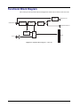
This section provides the functional block diagram that outlines the workflow of the VAC-100.
BYPASS
HD/SD-SDI IN
EQUALIZE/
DESERIALIZE
ENCODE
VANC
HD/SD-SDI OUT
SERIALIZE
HD/SD-SDI MON OUT
EXTRACT
VANC
CPU
GPIOs
LTC IN
Figure 1.1 Simplified Block Diagram — VAC-100
1–4 • Introduction
VAC-100 User Manual (Iss. 03)
User Interfaces
The VAC-100 provides the following user interfaces for controlling and monitoring the
VAC-100.
DashBoard Control System™
The DashBoard Control System™ enables you to monitor and control openGear frames and cards
from a computer. DashBoard communicates with other cards in the DFR-8300 series frame
through the MFC-8300 Series Network Controller Card. The DashBoard software and user
manual are available for download from our website.
For More Information...
•
on using DashBoard, refer to the DashBoard User Manual.
Card-edge Controls
The card-edge of the VAC-100 includes LEDs for monitoring the functions of the VAC-100.
For More Information...
•
on the switches available on the card-edge, refer to the section “Card Overview” on
page 3-2.
•
on the available LEDs, refer to the section “Control and Monitoring Features” on
page 3-3.
VAC-100 User Manual (Iss. 03)
Introduction • 1–5
Documentation Terms and Conventions
The following terms and conventions are used throughout this manual:
1–6 • Introduction
•
“Board”, and “Card” refer to openGear terminal devices within openGear frames,
including all components and switches.
•
“DashBoard” refers to the DashBoard Control System™.
•
“DFR-8300 series frame” refers to all versions of the 20-slot (DFR-8321 series frames)
and any available options unless otherwise noted.
•
“Frame” refers to DFR-8300 series frame that houses the VAC-100 card, as well as any
openGear frames.
•
“GPIO” refers to the DC signals used by one device to control another (General Purpose
Input-Output).
•
“Metadata” some of the VANC data that the VAC-100 monitors (such as closed
captioning) is “data essence”, not metadata. For convenience, this manual uses the term
“metadata” to refer to all VANC data types.
•
“Operator” and “User” refer to the person who uses VAC-100.
•
“System” and “Video system” refer to the mix of interconnected production and terminal
equipment in your environment.
•
“VANC” refers to the Vertical Ancillary Data space of a serial digital video signal, and is
defined by SMPTE-291M.
•
The “Operating Tips” and “Note” boxes are used throughout this manual to provide
additional user information.
VAC-100 User Manual (Iss. 03)
Installation
In This Chapter
This chapter provides instructions for installing the VAC-100, installing the card into the frame,
cabling details, and updating the card software.
The following topics are discussed:
•
Before You Begin
•
Quick Start
•
Installing the VAC-100
•
Cabling for the VAC-100
•
Software Upgrades
VAC-100 User Manual (Iss. 03)
Installation • 2–1
Before You Begin
Before proceeding with the instructions in this chapter, ensure that your DFR-8300 series frame is
properly installed according to the instructions in the DFR-8300 Series User Manual.
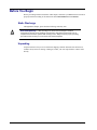
Static Discharge
Throughout this chapter, please heed the following cautionary note:
ESD Susceptibility — Static discharge can cause serious damage to sensitive
semiconductor devices. Avoid handling circuit boards in high static environments such as
carpeted areas and when synthetic fiber clothing is worn. Always exercise proper grounding
precautions when working on circuit boards and related equipment.
Unpacking
Unpack each VAC-100 you received from the shipping container and ensure that all items are
included. If any items are missing or damaged, contact your sales representative or Ross Video
directly.
2–2 • Installation
VAC-100 User Manual (Iss. 03)
Quick Start
The purpose of the VAC-100 is to decode VANC data and overlay this information on the video.
This section outlines the steps needed to get started with VANC metadata insertion:
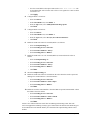
1. Install the VAC-100 into the frame.
2. Configure the VAC-100 using the options in DashBoard.
3. Connect GPIOs to control what is inserted.
Installing the VAC-100
1. Connect the frame to your LAN. Refer to the DFR-8300 Series User Manual and the
MFC-8300 Series User Manual for information.
2. Install DashBoard on a computer connected to the LAN. The DashBoard Control
System™ software and user manual is available from the Ross Video website.
3. Install a rear module in the frame, as described in the section “Installing a Rear
Module” on page 2-5.
4. Install a VAC-100 into the rear module, as described in the section “Installing the
VAC-100” on page 2-6.
5. Connect a SMPTE 292 or 259 video signal to the SDI input jack on the rear module as
described in the section “Cabling for the VAC-100” on page 2-7.
6. Connect the SDI output jack to an SDI analyzer or VANC monitoring test set.
7. Power on the frame.
Configuring the VAC-100
In this section, the VAC-100 is assumed not to be in Bypass mode and the card will append its
VANC data after any that is currently in the line.
1. Launch the DashBoard client on your computer.
•
DashBoard should automatically find your frame within a minute or two.
•
Expand the frame node you installed the VAC-100 in. A list of cards in the frame is
displayed.
•
Double-click the node for the VAC-100 you wish to configure for encoding. A tab
for the card displays in the Device View of the DashBoard client.
2. Re-name the card as follows:
•
Select the Settings tab.
•
Re-name the card. This will make the card easily identifiable within DashBoard
especially when there is more than one card to configure and monitor. Ensure to
press Enter after typing the name to apply the change.
3. Name the buffers as follows:
VAC-100 User Manual (Iss. 03)
•
Select the Edit Buffer Names tab. In this example, we will create two AFD packets
which allows the AFD format to be user-configurable since only one is allowable.
•
Give the first buffer a descriptive name such as “AFD Full Frame”. The first AFD
buffer will be for a default AFD code.
Installation • 2–3
•
Give the second buffer a descriptive name such as “AFD 16:9 C-cut 4:3”. The
second AFD buffer will be for the code to force a 16:9 signal to be center cut when
converted to 4:3.
•
Click Apply.
4. Configure Buffer 1 as follows:
•
Select the AFD tab.
•
In the Select Buffer area, select Buffer 1.
•
From the Type menu, select 1000 (8) full frame image prefer.
•
Click Save.
5. Configure Buffer 2 as follows:
•
Select the AFD tab.
•
In the Select Buffer area, select Buffer 2.
•
From the Type menu, select 1111 (15) 16:9 with 4:3 alternative.
•
Click Save.
6. Enable the AFD code 1000 to be encoded (Buffer 1) as follows:
•
Select the Setup Encoding tab.
•
Set the Encoding Service to Encode 1.
•
Set the Encode Condition to Always.
•
Set the Encoding Source to Buffer 1.
7. Enable the AFD code 1111 to be encoded (Buffer 2) an inserted into the video as
follows:
•
Select the Setup Encoding tab.
•
Set the Encoding Service to Encode 2.
•
Set the Encode Condition to Always.
•
Set the Encoding Source to Buffer 2.
•
Click Start.
8. Select the Setup Encoding tab.
9. Enable the AFD code 1000 to be encoded into the video when the switch is open and
nothing to be encoded when it is closed as follows:
•
Set the Encoding Service to Encode 1.
•
Set the Encode Condition to GPIO 1 Open.
•
Set the Encoding Source to Buffer 1.
•
Click Start.
10. Enable the switch to control Buffer 1 when the GPIO is open and control Buffer 2 when
the GPIO is closed as follows:
•
Set the Encoding Service to Encode 2.
•
Set the Encode Condition to GPIO 1 Closed.
•
Set the Encoding Source to Buffer 2.
•
Click Start.
You have now followed the basic work flow for authoring and inserting VANC data. The
VAC-100 supports the authoring of many types of VANC data. The details of the different types
are described later in the manual and may be referenced while experimenting with the card’s
abilities.
2–4 • Installation
VAC-100 User Manual (Iss. 03)
Installing the VAC-100
This section outlines how to install a rear module and card in a DFR-8300 series frame. Refer to
the section “Cabling for the VAC-100” on page 2-7 for cabling details.
Rear Modules for the VAC-100
When installing the VAC-100:
•
DFR-8310 series frames — The MDL-R10 Full Rear Module is required. The VAC-100
is not compatible with the DFR-8310-BNC frames.
•
DFR-8321 series frames — The MDL-R20 Full Rear Module is required.
Installing a Rear Module
If the rear module is already installed, proceed to the section “Installing the VAC-100” on page
2-6.
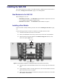
Use the following procedure to install a rear module in your DFR-8300 series frame:
1. Locate the card frame slots on the rear of the frame.
2. Remove the Blank Plate from the slot you have chosen for the VAC-100 installation.
3. Install the bottom of the Rear Module in the Module Seating Slot at the base of the
frame’s back plane. (Figure 2.1)
Screw Hole
Module Seating Slot
Figure 2.1 Rear Module Installation in a DFR-8300 Series Frame (VAC-100 not shown)
4. Align the top hole of the Rear Module with the screw on the top-edge of the frame back
plane.
5. Using a Phillips screwdriver and the supplied screw, fasten the Rear Module to the back
plane of the frame. Do not over tighten.
6. Ensure proper frame cooling and ventilation by having all rear frame slots covered with
Rear Modules or Blank Plates.
VAC-100 User Manual (Iss. 03)
Installation • 2–5
Installing the VAC-100
Use the following procedure to install the VAC-100 in a DFR-8300 series frame:
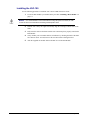
1. Locate the Rear Module you installed in the procedure “Installing a Rear Module” on
page 2-5.
Notice — It is recommended to use a frame with the cooling fan option in all cases, in order
to allow all slots to be used without exceeding heat dissipation limits.
2. Hold the VAC-100 by the edges and carefully align the card-edges with the slots in the
frame.
3. Fully insert the card into the frame until the rear connection plus is properly seated in the
Rear Module.
4. Verify whether your rear module label is self-adhesive by checking the back of the label
for a thin wax sheet. You must remove this wax sheet before affixing the label.
5. Affix the supplied rear module label to the BNC area of the Rear Module.
2–6 • Installation
VAC-100 User Manual (Iss. 03)
Cabling for the VAC-100
This section provides information for connecting cables to the installed Rear Modules on the
DFR-8300 series frames. Connect the input and output cables according to the following sections.
It is not necessary to terminate unused outputs.
Rear Module Cabling
This section provides cabling diagrams for the rear modules. The type of rear module you need
depends on the frame the card will be installed in.
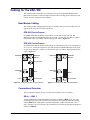
DFR-8310 Series Frames
Each MDL-R10 Full Rear Module accommodates one card and occupies two slots. The
MDL-R10 provides one HD/SD/SDI input, an LTC input, a bypass relay from BNC 1 to BNC 3,
bi-directional Logic-level GPIOs, and a monitoring video output. (Figure 2.2)
DFR-8321 Series Frames
Each MDL-R20 Full Rear Module accommodates one card which must be in an even-numbered
slot (2, 4, 6 etc.). Each card occupies two slots and provides one HD/SD/SDI input, an LTC input,
a bypass relay from BNC 1 to BNC 3, bi-directional Logic-level GPIOs, and a monitoring video
output. (Figure 2.3)
HD/SD-SDI
In
1 2
HD/SD-SDI
MON Out
HD/SD-SDI
In
1 2
HD/SD-SDI
MON Out
Not connected
4
3
HD/SD-SDI
Out
GPIOs
HD/SD-SDI
Out
5 6
LTC In
3
GPIOs
4 5
Not connected
Figure 2.2 Cabling for the MDL-R10 Rear Module
LTC In
Not connected
Figure 2.3 Cabling for the MDL-R20 Rear Module
Connections Overview
This section briefly outlines the types of connections available on the rear modules.
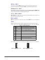
SDI In — BNC 1
An SDI (SMPTE 259) or HD-SDI (SMPTE 292) input is available on BNC 1. The VAC-100
requires this input in all cases. It inserts VANC packets into this signal and routes the resulting
output to BNC 3. The input signal is internally terminated in 75ohms when the VAC-100 is
active; when the VAC-100 is in bypass, the termination is provided by the downstream equipment
connected to BNC 3.
VAC-100 User Manual (Iss. 03)
Installation • 2–7
SDI Out — BNC 3
This output is available on BNC 3. This BNC carries the main program output from the
VAC-100, consisting of the signal applied to BNC 1, with VANC data packets inserted.
SDI Monitor Out — BNC 2
When the VAC-100 is active, this jack carries a copy of the SDI output present on BNC 3. This
can be useful for test purposes. This BNC does not have any bypass capability: with power off or
the VAC-100 removed, there is no output signal on this jack.
LTC In — BNC 4 or BNC 5
BNC 4 (BNC 5 on the MDL-R10) accepts an LTC time source which the VAC-100 can use as a
time source when generating timecodes.
BNC 5 or BNC 6
BNC 5 on the MDL-R20 is not used by the VAC-100 while BNC 6 is not used on the MDL-R10.
GPIOs
GPIOs can be used to remotely control the operation of the VAC-100 by means of contact
closures. VANC services can be enabled or disabled on one or more of these inputs.(Table 2.1)
Table 2.1 GPIO Connections
Pin
Function
Connection
1
GPI 1
Connect to Ground to assert; open to negate
2
GPI 1 presence
Connect to Ground to enable GPI 1a
3
GPI 2
Connect to Ground to assert; open to negate
4
GPI 2 presence
Connect to Ground to enable GPI 2a
5
GPI 3
Connect to Ground to assert; open to negate
6
GPI 3 presence
Connect to Ground to enable GPI 3a
7
GPI 4
Connect to Ground to assert; open to negate
8
GPI 4 presence
Connect to Ground to enable GPI 4a
9
Ground
a.
You must reboot the card whenever you reconfigure the GPIO.
Refer to Figure 2.4 for pinouts on the MDL-R10 and Figure 2.5 for pinouts on the MDL-R20.
G
8
7
6
5
4
3
2
1
Figure 2.4 GPIO Pinouts for the
MDL-R10
2–8 • Installation
1
2
3
4
5
6
7
8
G
Figure 2.5 GPIO Pinouts for the
MDL-R20
VAC-100 User Manual (Iss. 03)
Software Upgrades
This section provides instructions for upgrading the software for your VAC-100 using the
DashBoard Control System™.
Use the following procedure to upgrade the software on a VAC-100:
1. Contact Ross Technical Support for the latest software version file.
2. Launch the DashBoard client on your computer.
3. Display a tab for the card you wish to upgrade by double-clicking its status indicator in
the Basic Tree View.
4. From the Device tab, click Upload to display the Select File for upload dialog box.
5. Navigate to the *.bin upload file you wish to upload.
6. Click Open and follow the on-screen instructions.
7. Click Finish to start the upgrade.
8. Monitor the upgrade.
•
A Upload Status dialog enables you to monitor the upgrade process.
•
The card reboots automatically once the file is uploaded. The card is temporarily
taken offline.
•
The reboot process is complete once the status indicators for the Card State and
Connection return to their previous status.
Operating Tip — If you are running DashBoard version 2.3.0 or lower, you must
click Reboot in the Device tab to complete the upgrade process.
This completes the procedure for upgrading the software on a VAC-100.
Troubleshooting
If you encounter problems when upgrading your card software, verify the following:
•
Ethernet cable is properly connected if you are uploading the file via a network
connection.
•
The file you are attempting to load is a *.bin file that is for the card you are upgrading.
VAC-100 User Manual (Iss. 03)
Installation • 2–9
2–10 • Installation
VAC-100 User Manual (Iss. 03)
User Controls
In This Chapter
This chapter provides a general overview of the user controls available on the VAC-100.
The following topics are discussed:
•
Card Overview
•
Control and Monitoring Features
VAC-100 User Manual (Iss. 03)
User Controls • 3–1
Card Overview
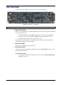
This section provides a general overview of the VAC-100 card components.
1
2
3
Figure 3.1 VAC-100 — Components
1) Bypass Switch (SW1)
2) Menu Switch (SW2)
3) Reset Switch (SW3)
1. Bypass Switch (SW1)
If the VAC-100 is installed in a rear module that has a bypass relay, this two-position push-button
is used to control the relay.
•
When the push-button is in the IN position, the VAC-100 is in the video signal path.
•
Pressing it once moves the switch to the OUT position and bypasses the VAC-100.
•
Pressing it again restores the VAC-100 to its active state.
When the VAC-100 is installed in a rear module that does not provide bypass capability, this
switch enables and disables VANC encoding.
2. Menu Switch (SW2)
This switch is not implemented on the VAC-100.
3. Reset Switch (SW3)
This button is used for rebooting the card. Refer to the section “Reset Button” on page 6-2 for
details on using this button.
For More Information...
•
3–2 • User Controls
on the LEDs available on the card-edge, refer to the section “Control and Monitoring
Features” on page 3-3.
VAC-100 User Manual (Iss. 03)
Control and Monitoring Features
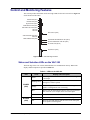
This section provides information on the card-edge LEDs for the VAC-100. Refer to Figure 3.2
for the location of the LEDs.
POWER LED (DS1)
BYPASS LED (DS2)
Bypass Switch (SW1)
PGM VIDEO IN LED (DS3)
PGM VIDEO OUT LED (DS4)
DS5 LED
DS6 LED
Menu Switch (SW2)
VANC ENCODE LED (DS7)
DS8 LED
VIDEO ERROR LED (DS9)
UNKNOWN REAR MODULE LED (DS10)
INVALID INSERTION LINE LED (DS11)
NO VIDEO LED (DS12)
Reset Button (SW3)
Figure 3.2 VAC-100 Card-edge Controls
Status and Selection LEDs on the VAC-100
The front-edge of the VAC-100 has LED indicators for communication activity. Basic LED
displays and descriptions are provided in Table 3.1.
Table 3.1 LEDs on the VAC-100
LED
POWER
(DS1)
BYPASS
(DS2)
VAC-100 User Manual (Iss. 03)
Color
Display and Description
Green
When lit green, this LED indicates that the card is running with
a valid input.
Flashing Green
When flashing green, this LED indicates that the bootloader is
waiting for a software upload.
Orange
When lit orange, this LED indicates there is a warning for a
signal or a configuration error is occurring.
Red
When lit red, this LED indicates that the card is not operational.
This will occur if, for example, there is not video input.
Off
When off, this LED indicates that there is no power.
Red
When lit red, this LED indicates the card video is bypassed.
Off
When off, this LED indicates that the card is in the video path
and is capable of inserting data.
User Controls • 3–3
Table 3.1 LEDs on the VAC-100
LED
PGM VID IN
(DS3)
PGM VID
OUT (DS4)
Color
Green
When lit green, this LED indicates the Program Video input is
present and valid.
Red
When lit red, this LED indicates no valid input is present.
Ensure the input cable is connected properly.
Green
When lit green, this LED indicates the Program Video output
serializer is locked to a valid input.
Red
When lit red, this LED indicates there is a hardware fault on the
card.
DS5
This LED is not implemented.
DS6
This LED is not implemented.
VANC
ENCODE
(DS7)
Green
When lit green, this LED indicates the VAC-100 is inserting
VANC data into the video.
Yellow or
Flashing
Yellow/Green
When lit yellow or flashing yellow/green, this LED indicates
there is too much VANC data to fit in the specified line(s), and
some data is being lost.
Off
When off, this LED indicates there is no insertion.
This LED is not implemented.
DS8
VIDEO
ERROR
(DS9)
Green
When lit green, this LED indicates no video errors are
occurring.
Yellow
When lit yellow, this LED indicates that there has been an error
(e.g. EDH) in the video input stream
UKNOWN
REAR
MODULE
(DS10)
Green
When lit green, this LED indicates a supported rear module is
installed with the card.
Yellow
When lit yellow, this LED indicates this indicates that the rear
module connected to the VAC-100 is not one of the types
recognized by the software. Operation may not be correct.
Green
When lit green, this LED indicates the card is configured to
insert VANC data in a valid line.
Red
When lit red, this LED indicates this indicates that the VAC-100
has been set to insert VANC data into an invalid line, that is a
line that is not in the vertical interval for the current video
format.
Green
When lit green, this LED indicates a valid video input.
Red
When lit red, this LED indicates that no video is present at the
input.
INVALID
INSERTION
LINE (DS11)
NO VIDEO
(DS12)
3–4 • User Controls
Display and Description
VAC-100 User Manual (Iss. 03)
Configuration
In This Chapter
This chapter explains how to use DashBoard to set up the VAC-100. This discussion is based on
the use of DashBoard through a network connection. The order of sections in this chapter follows
the workflow required to set up the VAC-100 for operation.
The following topics are discussed:
•
General Settings
•
Setting the Time Source
•
Naming the Data
•
Authoring the Data
•
Inserting the Data
•
Configuring the Alarms
•
Monitoring
•
Managing User Settings
VAC-100 User Manual (Iss. 03)
Configuration • 4–1
General Settings
This section provides a summary of the initial tasks you may wish to perform before configuring
your card for inserting data VANC services. Before proceeding to any of the other sections,
please ensure that these settings are correct, as they will have an effect on the operation of the
other functions.
To configure the general settings
1. Select the Settings tab.
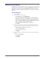
2. Type a unique name for your card in the Card ID field. This is especially useful if you
have more than one VAC-100 in a frame. If this field were blank, the name would just be
“VAC-100”.
3. Configure the Remote Bypass Control as follows:
•
Select Active to allow the VAC-100 to insert VANC data into the video. This is the
default.
•
Select Bypass during maintenance operations such as software updates, for example
– provided, of course, that the rear module has bypass capability.
4. Configure the Encode Mode as follows:
•
Select Append to allow the VAC-100 to add your VANC data services after any that
are present on the same line(s) of the input signal. This is the preferred mode of
operation, since it adds your VANC data services with no effect on any others.
Append will be used, regardless of the Encode Mode setting, for data inserted into
the H-VANC space.
•
Select Overwrite to eliminate incoming VANC services from the output. Note that
this only affects lines encoded. Other lines will pass untouched.
•
Select Prepend to place your VANC services before any incoming services in the
lines. You might choose this if you want to give priority to your locally-added
services in the case where there may be insufficient space in the line(s) for both
incoming and local services.
Notice — About Append and Prepend modes: when you insert a VANC service into a
signal that already contains packets with the same DID and SDID as the service that you
are adding, the VAC-100 either deletes the incoming packets before inserting its own, or
refrains from inserting to allow the incoming data to flow through; this depends on the
Priority setting in the Setup Encoding tab. This eliminates any possible confusion caused
by two or more versions of the same service.
5. If you plan to use the on-screen display, configure the OSD Background Color and
OSD Video Type as required. The OSD Background Color and Video Type default to
black and 525 lines/59.94 Hz, respectively.
6. You can save the Configuration of the card to a file on a PC by clicking Save.
7. The Factory Defaults Reset button clears all configuration settings and restores the
settings to the values they had when shipped from the factory.
4–2 • Configuration
VAC-100 User Manual (Iss. 03)
Setting the Time Source
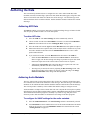
The Time tab enables you to specify whether the VAC-100 acquires the time over the network
from an NTP server or the time and date is set manually. The Time Source radio buttons control
which method is used. The time is shown on the Program status tab and may be used by the
Timecode tab. It is highly recommended that an NTP time server be used if timecode will be use
it as a source.
To set the time source
1. Select the Time tab.
2. To use an NTP server as the time source:
•
In the Time Source area, select Network Time.
•
Specify your time offset from Universal Time (UTC), as a positive or negative
number of hours and minutes in the UTC Offset area. For example, the area of
North America where Pacific time is observed is 8 hours west of longitude 0; the
settings would be UTC Offset: HH = 8, MM = 0 and Hemisphere = West. Note
that UTC is also known as GMT (Greenwich Mean Time).
•
Enable or disable DST (Daylight Savings Time) as appropriate.
•
Click Accept.
3. In order to use network time, you also need to ensure that the network card in the
openGear frame has been configured to acquire time from an NTP server. To do this:
•
Double-click the network card in slot 0 of the frame.
•
Select the Network Settings tab.
•
Enter the IP address of the NTP server.
•
Click Apply.
4. If you do not have access to an NTP server, you can enter the time and date directly as
follows:
VAC-100 User Manual (Iss. 03)
•
Select the Time Settings tab.
•
Select Manual.
•
Click Accept.
Configuration • 4–3
Naming the Data
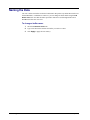
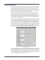
The VAC-100 has ten buffers in which to build VANC data packets. By default these buffers are
labeled Metadata 1 to Metadata 10. However, you can change the buffer labels using the Edit
Buffer Names tab. Note that the names specified in this tab are used throughout the tabs in
DashBoard for that VAC-100 card.
To change a buffer name:
1. Select the Edit Buffer Names tab.
2. Type a new label in the field for each buffer you wish to re-name.
3. Click Apply to apply the new name(s).
4–4 • Configuration
VAC-100 User Manual (Iss. 03)
Authoring the Data
This section briefly summarizes how to configure the VAC-100 to author AFD data, audio
metadata, timecode, broadcast flags, caption test data, ISAN data, DPI triggers, and generic data.
There are ten buffers each which can contains one VANC data type. The same data type with
different attributes can be in different buffers. Buffers should be named to indicate their content
and usage.
Authoring AFD Data
The AFD tab enables you to assign a AFD code to a buffer and change the type of data in a buffer.
You can specify whether bar data is set in the AFD packet.
To author AFD data:
1. Select the AFD tab. The VANC Settings sub-tab is automatically selected.
2. Choose a buffer from the list in Select Buffer. The name is created in the Edit Buffer
Names tab as described in the section “Naming the Data” on page 4-4.
3. Select the AFD code from the Type list and the Bar Data status will update as required.
4. Most AFD codes do not require bar data, some do but all can have bar data set. If you do
not wish to include bar data then click the Metadata Save button to create a AFD
packet without bar data.
5. If you wish to set bar data, select the Bar Data tab at the bottom of the AFD tab.
•
Select the Force Bar Data box and choose the Video Format for which the bar
data is to apply. The bar data settings will change to produce an aspect ratio which
matches the aspect ratio of the selected video so that no bars are required.
•
Adjusting the Aspect Ratio slider causes bar data to be required. The VAC-100
automatically calculates bar data to center the image.
•
The image may be moved off center by adjusting the Bar Percentage slider. This
adjusts the percentage of bar which is on the top or left of the image. The Image
Position and Bar Data status change with this adjustment.
Authoring Audio Metadata
The VAC-100 provides several settings tabs to allow for the easy creation of VANC data. There
are ten buffers each of which can contain one VANC data type. The same data type with different
attributes can be in different buffers. Buffers should be named to indicate their content and usage.
This section provides a summary of the available tabs and the settings to configure in each.
Audio metadata is a complex form of VANC data. The VAC-100 puts the tools in place to quickly
and efficiently generate audio metadata which complies with SMPTE-2020 both method A and B.
The metadata for the different programs is normally very similar so copy and paste can be
effectively used to limit the number of fields that need to change in the other programs.
To configure the VANC settings for the audio metadata
1. Select the Audio Metadata tab. The VANC Settings sub-tab is automatically selected.
2. Use Select Buffer to choose which buffer to use for this audio metadata data. The buffer
name can be set to any text on the Edit Buffer Names tab as described in the section
“Naming the Data” on page 4-4.
VAC-100 User Manual (Iss. 03)
Configuration • 4–5
3. Select an Encode Method.
4. Selecting the Program Config from the list determines the number of programs. All
settings must be made for each program.
5. Select an appropriate Frame Rate from the list.
6. Click Save to apply the changes.
To set up programs
1. From the Audio Metadata tab, select the Program sub-tab.
2. The Number Of Programs status field indicates how many programs will have to be set
up. This involves filling in all the fields of the Program, XBS and Flags tabs for each of
the programs. The easiest way to accomplish this is to use the Program Copy and
Program Paste buttons.
3. Set up a specific Program as follows:
•
Select the program from the Program Number list.
•
Type a name in the Program Name field.
•
On the Program, XBS and Flags tabs, change only the settings that require setting.
4. It is advisable but not necessary to click Save after setting up each program.
5. Click the Metadata Save button to save the work to this point.
6. To copy and paste one program settings to another:
•
Click the Program Copy button to get a copy of the current program’s settings.
•
Select the next program from the Program Number list and give it a name in the
Program Name field.
•
Click the Program Paste button to make this program’s settings the same as the
previous program.
•
On the Program, XBS and Flags tabs, change only the settings that require setting.
Repeat this process until all parameters of all programs are set.
7. It is advisable but not necessary to click Save to apply your changes after setting up
each program.
Authoring Timecode
The Timecode tab enables you to specify the buffer to use for timecode data, and select the time
source and type.
To author a timecode
1. Select the Timecode tab.
2. Use Select Buffer to choose which buffer to use for timecode data.
3. If you wish to assign a unique name to the buffer selected above, refer to the section
“Naming the Data” on page 4-4.
4. Select a source for the time data for the timecode from the Timecode Source area in the
Timecode tab. Note that the VANC may include two types of timecode on three possible
lines. Normally the first timecode found anywhere in the VANC is the one displayed.
5. Select a Timecode Type.
6. When using Jam mode:
4–6 • Configuration
VAC-100 User Manual (Iss. 03)
•
The timecode counts up from the time shown on the Timecode tab (as specified by
the HH, MM, and SS fields).
•
Click Jam to start the count. When controlling timecode insertion with a GPIO or
timed activation (refer to the section “Inserting the Data” on page 4-10), the
timecode value is jammed to the value shown on the Timecode tab whenever
timecode insertion is turned on by the GPIO or timed interval.
Authoring Broadcast Flags
The Broadcast Flag tab provides the Select Buffer menu that enables you to choose which
buffer to use for the broadcast flag. The buffer name can be set to any text on the Edit Buffer
Name tab as described in the section “Naming the Data” on page 4-4. The Broadcast flag has no
parameters to set, so click Save to store it in the buffer.
Authoring Caption Test Data
The Closed Captions tab enables you to author caption test data and insert it into both the 608
and DTVCC sections of the SMPTE-334 / CEA-708 caption packet.
To create a captioning test sequence
1. Select the Closed Captions tab.
2. Use Select Buffer to choose which buffer to use for the captioning test. The buffer name
can be set to any text on the Edit Buffer Name tab as described in section “Naming the
Data” on page 4-4.
3. Use the Interval slider to specify the number of seconds between transmissions of the
lines of caption text.
4. Select the Sequence box to cause the software to prepend a counter to the start of each
line of caption text.
5. Each of the four text fields contains the text for a single line of captioning. Each line can
be zero to 32 characters long and may only contain printable characters.
6. Click Save to store the caption test into the specified buffer.
Authoring ISAN Data
The ISAN tab is used to enter a V-ISAN (International Standard Audiovisual Number with
Version). ISAN codes are shown in the form of: RRRR-RRRR-RRRR-EEEE-X-VVVV-VVVV-Y. The
VAC-100 KLV-encodes this number in accordance with SMPTE 336 and embeds it in a VANC
packet as specified in SMPTE RP214.
To author ISAN data
1. Select the ISAN tab.
2. Use Select Buffer to choose which buffer to use for the ISAN data. The buffer name can
be set to any text on the Edit Buffer Name tab as described in section “Naming the
Data” on page 4-4.
3. The length of the code makes it advisable to cut and paste the code rather than trying to
type it in. The codes are protected by check codes and this tab checks the code when the
Save button is clicked.
VAC-100 User Manual (Iss. 03)
Configuration • 4–7
•
If the code is correct, the ISAN Status field displays a green indicator and the
message “OK”.
•
If the code is not the right length or the correct sequence, the ISAN Status field
displays a red indicator and the message “Syntax Error”.
•
If the length and syntax are correct but a character is incorrect, the ISAN Status
field displays a red indicator and the message “Invalid Check Code”.
4. Click Save to save the data into the specified buffer.
Authoring DPI Triggers
The DPI Trigger tab is used to author SMPTE 2010 VANC packets containing SCTE 104 trigger
commands. The configurable parameters on this screen are all included in the inserted VANC
packet. For more details, consult the SMPTE 2010, SCTE 104 and SCTE 35 standards.
To author VANC packets containing SCTE 104 trigger commands
1. Select the DPI Trigger tab.
2. Use Select Buffer to choose which buffer to use for the DPI trigger. The buffer name
can be set to any text on the Edit Buffer Name tab as described in section “Naming the
Data” on page 4-4.
3. Set the tab parameters of the trigger in a way appropriate to its use.
4. Click Save.
5. Use the Auto Increment Avail Num box to increment the Avail Num for each time the
trigger is sent. This box is used in conjunction with the encoding of the trigger when
controlled by a GPIO switch or timed activation.
6. Clicking Save will restore the Avail Num to the value set on the screen.
Authoring Generic Data
Generic data is a catch-all for VANC data which is not directly supported with an authoring tab.
For example, generic data authoring is used to create text tags. Text tags identify the source of a
video stream so that it can be tracked through the plant.
To author generic data
1. Select the Generic Data tab.
2. Use Select Buffer to choose which buffer to use for the generic data. The buffer name
can be set to any text on the Edit Buffer Name tab as described in the section “Naming
the Data” on page 4-4.
3. Use the DID, SDID, Line and Encode Channel fields to determine where in the VANC
the generic data will be inserted by default. Set these to values appropriate to the
standard to which the data is being authored. For private data, not covered by a standard,
this should match the equipment being used to capture or monitor the data.
4. Enter the generic data. There are ten text fields available for this purpose allowing for
the creation of a packet up to the 255 byte maximum size.
4–8 • Configuration
•
Blank fields are not part of the generic data nor is any non-used portion of a field.
•
What you enter into the field is what is placed in the generic record.
VAC-100 User Manual (Iss. 03)
•
Use a backslash (\) to put non-printable characters into the record. The two
characters after the backslash will be taken as a hex value to create a single
character.
•
Use two backslashes (\\) in a row to put a single backslash character into the record.
5. Click Save to save the record into the buffer.
VAC-100 User Manual (Iss. 03)
Configuration • 4–9
Inserting the Data
The VAC-100 can insert zero to four encode services at a time from a selection of ten buffers
containing authored data. The first step is to select which Encoding Service you wish to define
and which Encode Source (authored data) to encode in that service. The Encode Condition
determines when and how the data is encoded. There are three choices for how to encode data;
Always, Timed Interval and by GPIO (switch) control. When set to Always, the VANC data is
sent in every field of the video (or every frame of progressive formats).
Timed Interval and GPIO Open/Closed use the Frame Count field to specify the number of
successive frames in which the VANC data is inserted. When the Encode Condition is set to
Timed Interval, the VANC service is inserted in the number of frames specified by Frame Count,
and then not inserted for the period of time specified by Time Interval (msec), and this cycle
repeats endlessly. This would typically be used for services such as the Broadcast Flag which
must be inserted once every 2 seconds.
Switches connected to GPIOs may also control when a VANC data record is sent. The GPIOs
have two states: open and closed. Data may be inserted under either of these conditions. A single
switch state may control more than one encode buffer. This can cause more than one VANC
service to turn on when the switch does. By assigning different services to the open and closed
states of a GPIO, you can use one switch to select between the two services. To cause a service to
be inserted indefinitely when the specified GPIO condition occurs, set Frame Count = 0. If Frame
Count is not 0, the service will be inserted for the specified number of frames after the GPIO
condition occurs, and then stop. An example of this latter use would be DPI triggers which can be
inserted a few times to ensure that they are not missed by receiving equipment.
Setup Encoding Tab
The rest of the fields of this tab control the line, channel and address used for inserting the VANC
service. Authored data has default settings assigned to it. This is usually the value suggested by a
standards document. The VANC Preview Area shows what the default values are in the format
[line][channel] [DID]:[SDID] Size=[field1],[field2]. These will normally be the desired settings
so the DID and SDID Select, Encode Line Selection and Encode Channel can all be set to default.
To use a non-standard setting, set the value and choose Custom.
4–10 • Configuration
VAC-100 User Manual (Iss. 03)
Click Start to make the encode buffer active and the authored data will be inserted according to
the rules you have set. To disable an encode buffer, set the Encoding Source to Nothing and
click Start.
VAC-100 User Manual (Iss. 03)
Configuration • 4–11
Configuring the Alarms
The Alarms tab allows you to specify which conditions in the VAC-100 will cause an alarm
indication on your DashBoard screen. Whenever any of the enabled alarm conditions becomes
true, the color of the indicator for the VAC-100 on the DashBoard screen switches from green to
red.
To configure the alarms
1. Select the Alarms tab.
2. Select the Upstream Encoding Overflow box to raise an alarm when there is an attempt
to add more data than could fit in the specified line(s). The total of existing plus added
data does not fit in the line(s). If this alarm is enabled and this condition occurs, the
Encoding Status on the Alarms status tab will display “Overflow”.
3. Select the Local Encoding Overflow box to raise an alarm when an attempt to insert
more data than could fit in the specified line(s) occurs. The total of the added data
services overflows the capacity of the line(s). If this alarm is enabled and this condition
occurs, the Encoding Status on the Alarms status tab will display “Overflow”.
4. Select the Unknown Rear Module box to raise an alarm when the VAC-100 is plugged
into a rear module that it does not recognize. This could have an effect on the video
output, since the types and locations of jacks are unknown. If this alarm is enabled and
this condition occurs, the Rear Module field on the Alarms status tab will display
“Unknown”.
5. Select the Invalid Line box to raise an alarm when there has been an attempt to insert
VANC data in a line that is not part of the vertical interval (for example, line > 20 for
1080i/59.94). If this alarm is enabled and this condition occurs, the Encoding Line field
on the Alarms status tab will display “Invalid”.
6. Select the Loss of Video box to raise an alarm when there is no video signal detected.
This normally an emergency and should therefore always be enabled. If it is and this
condition occurs, the Video Presence field on the Alarms status tab will display
“Missing”.
7. Select the Error in Video box to raise an alarm when a detectable video error, such as
an EDH or CRC error, has occurred in the input video. If enabled, this alarm causes the
status to blink briefly from green to red when an error occurs, and stay red if errors are
occurring constantly. If this alarm is enabled and this condition occurs, the Video Status
field on the Alarms status tab will display “Error”.
8. Select the Encoder in Bypass box to raise an alarm when the VAC-100’s video is
bypassed for some reason. This could be because it has been set to Bypass on the
Settings menu, or the card-edge Bypass push-button is in the OUT position, or because
of a fault condition. If this alarm is enabled and this condition occurs, the Bypass
Switch field on the Alarms status tab will display “Bypass”.
9. Select the Time Of Day box to raise an alarm when the time is not set while the time of
day is selected as a source of time codes.
10. Select the Incoming LTC box to raise an alarm when the LTC IN BNC does not have a
valid LTC input while LTC is selected as a source of time codes.
4–12 • Configuration
VAC-100 User Manual (Iss. 03)
Monitoring
This section provides a detailed explanation of the status tabs available when using DashBoard to
monitor the VAC-100.
Product Status
The Product tab displays information that is useful in discussing the operation of the module
with Ross Video's Technical Support staff. The Product tab has the name of the product and the
versions of software and hardware installed. The Saving Settings progress bar indicates when the
card is saving its settings to permanent flash memory. The card should not be powered down
while it is saving its configuration.
Incoming Services Status
The Incoming Services tab displays a list of VANC services that are present in the video input
signal. This includes the input video type, the last incoming LTC time code and indicates
whether the rear module is in active or bypass state.
It shows up to eight VANC services found in the VANC on the input to the card. These are labeled
Decode 1 through Decode 8. For each one, the following information is displayed:
•
Line number (e.g. 9)
•
HANC in VANC indicator (H or HANC, or nothing if VANC)
•
Component (L for luma or C for chroma)
•
DID:SDID (e.g. 50:01) These addresses are assigned by SMPTE to identify data services.
•
Packet size in bytes. If there are two packets they are shown as 64,30 if they are in
consecutive fields and as 64+30 if they are in the same field.
Outgoing Services Status
The Outgoing Services tab provides a list of VANC services that are currently being inserted into
the program video by the VAC-100. This shows the input video type, the last incoming LTC time
code and indicates whether the rear module is in the active or bypass state.
The four Encode lines show the VANC services that have been enabled using the Setup
Encoding tab. For each one, the following information is displayed:
•
Line number (e.g. 12)
•
HANC in VANC indicator (H or HANC, or nothing if VANC)
•
Component (L for luma or C for chroma)
•
DID:SDID (e.g. 50:01) These addresses are assigned by SMPTE to identify data services.
•
Service name (e.g. “AM Stereo”) This is the name assigned to the buffer in the Edit
Buffer Names tab.
GPIO Status
The GPIO Status tab reports the status of the four general purpose (GPIO) inputs. Each of these
ports has three pins, one of which indicates the presence of a connection. The status of each of the
inputs is consequently one of the three possible values: Not Connected (no switch currently
connected), Open (switch connected and open) or Closed (switch connected and closed).
VAC-100 User Manual (Iss. 03)
Configuration • 4–13
Alarm Status
The Alarms tab the status of the various conditions that are monitored. Each of these conditions
can be enabled or disabled on the Alarms settings tab. The Card Status field is a summary of
these indicators. It reports the most severe alarm condition that is present:
4–14 • Configuration
•
If all the indicators are green, the Card Status field displays a green indicator and the
message “OK”.
•
If any of the indicators are red, the Card Status field displays a red indicator and a brief
description of the underlying error condition.
VAC-100 User Manual (Iss. 03)
Managing User Settings
The VAC-100 enables you to save and load card configuration files to a *.bin file on your
computer. This file captures how the settings were configured, allowing you to apply them to
other cards of the same type. Alternatively, you can apply the factory default settings to the card.
To save user settings
1. Display a tab for the card you wish to upgrade by double-clicking its status indicator in
the Basic Tree View.
2. Select the Settings tab.
3. Click Save to display the Save file dialog.
4. Follow the on-screen instructions to save the card configuration (VAC-100-Config.bin)
to a directory on your computer.
To retrieve user settings
1. Display a tab for the card you wish to upgrade by double-clicking its status indicator in
the Basic Tree View.
2. Select the Settings tab.
3. Click Upload to display the Upload file dialog.
4. Navigate to the configuration file you wish to retrieve.
5. Click Refresh to apply the settings from the configuration file you selected in step 4.
To load the factory defaults
1. Ensure the DataSafe™ feature is disabled on the MFC-8300 series Network Controller
card in your frame. Refer to the MFC-8300 Series User Manual for details.
2. Display a tab for the card you wish to upgrade by double-clicking its status indicator in
the Basic Tree View.
3. Select the Settings tab.
4. Click Reset in the Factory Defaults area.
VAC-100 User Manual (Iss. 03)
Configuration • 4–15
4–16 • Configuration
VAC-100 User Manual (Iss. 03)
Specifications
In This Chapter
This chapter provides the technical specification information for the VAC-100. Note that
technical specifications are subject to change without notice.
The following topics are discussed:
•
Technical Specifications
VAC-100 User Manual (Iss. 03)
Specifications • 5–1
Technical Specifications
This section provides technical specifications for the VAC-100.
Table 5.1 VAC-100 Technical Specifications
Category
Parameter
Number of Inputs
Specification
1
480i 59.94 (SMPTE 259M)
576i 50 (SMPTE 259M)
Input Signal Standard
Accommodated
1080i 50, 59.94, 60 (SMPTE 292M)
720p 50, 59.94, 60 (SMPTE 292M)
1080p 23.98, 24 (SMPTE 292M)
SDI Inputs
1080psf 23.98, 24 (SMPTE 292M)
75ohm terminating in Active mode
Impedance
Loop-through to Video Output in Bypass mode
>100m of Belden 1694A cable @ 1.485Gbps
Equalization
400m @ 270Mbps
SDI Outputs
Return Loss
>13dB to 1.485GHz
Number of Outputs
2 outputs where 1 output is bypass-protected
Impedance
75ohm
Return Loss
10dB to 1.485GHz
Signal Level
800mV ±10%
DC Offset
0V ±50mV
700ps typical (270Mbps)
Rise & Fall Time (20-80%)
120ps typical (1.485Gbps)
LTC Input
Power
5–2 • Specifications
Overshoot
<8%
Number of Inputs
1 (SMPTE 12M)
Maximum Power Consumption
5W
VAC-100 User Manual (Iss. 03)
Service Information
In This Chapter
This chapter contains the following sections:
•
Troubleshooting Checklist
•
Warranty and Repair Policy
VAC-100 User Manual (Iss. 03)
Service Information • 6–1
Troubleshooting Checklist
Routine maintenance to this openGear product is not required. In the event of problems with your
VAC-100, the following basic troubleshooting checklist may help identify the source of the
problem. If the frame still does not appear to be working properly after checking all possible
causes, please contact your openGear products distributor, or the Technical Support department at
the numbers listed under the “Contact Us” section.
1. Visual Review — Performing a quick visual check may reveal many problems, such as
connectors not properly seated or loose cables. Check the card, the frame, and any
associated peripheral equipment for signs of trouble.
2. Power Check — Check the power indicator LED on the distribution frame front panel
for the presence of power. If the power LED is not illuminated, verify that the power
cable is connected to a power source and that power is available at the power main.
Confirm that the power supplies are fully seated in their slots. If the power LED is still
not illuminated, replace the power supply with one that is verified to work.
3. Re-seat the Card in the Frame — Eject the card and re-insert it into the frame.
4. Check Control Settings — Refer to the Installation and User Controls sections of this
manual to verify all user-adjustable component settings
5. Input Signal Status — Verify that source equipment is operating correctly and that a
valid signal is being supplied.
6. Output Signal Path — Verify that destination equipment is operating correctly and
receiving a valid signal.
7. Unit Exchange — Exchanging a suspect unit with a unit that is known to be working
correctly is an efficient method for localizing problems to individual units.
Reset Button
In the unlikely event of a complete card failure, you may be instructed by a Ross Technical
Support specialist to perform a complete software reload on the VAC-100.
Use the following procedure to reload the software on a VAC-100:
1. Press and hold the Menu switch.
2. While holding the Menu switch, press the Reset button in.
3. Release the Reset button and then the Menu switch.
6–2 • Service Information
•
The POWER LED will flash green while the card is waiting for a new software
load.
•
If a new software load is not sent to the card within 60 seconds, the card will
attempt to restart with its last operational software load.
•
Software loads can be sent to the VAC-100 via the connection on the rear of the
frame.
VAC-100 User Manual (Iss. 03)
Warranty and Repair Policy
The VAC-100 is warranted to be free of any defect with respect to performance, quality,
reliability, and workmanship for a period of FIVE (5) years from the date of shipment from our
factory. In the event that your VAC-100 proves to be defective in any way during this warranty
period, Ross Video Limited reserves the right to repair or replace this piece of equipment with a
unit of equal or superior performance characteristics.
Should you find that this VAC-100 has failed after your warranty period has expired, we will
repair your defective product should suitable replacement components be available. You, the
owner, will bear any labor and/or part costs incurred in the repair or refurbishment of said
equipment beyond the FIVE (5) year warranty period.
In no event shall Ross Video Limited be liable for direct, indirect, special, incidental, or
consequential damages (including loss of profits) incurred by the use of this product. Implied
warranties are expressly limited to the duration of this warranty.
This VAC-100 User Manual provides all pertinent information for the safe installation and
operation of your openGear Product. Ross Video policy dictates that all repairs to the VAC-100
are to be conducted only by an authorized Ross Video Limited factory representative. Therefore,
any unauthorized attempt to repair this product, by anyone other than an authorized Ross Video
Limited factory representative, will automatically void the warranty. Please contact Ross Video
Technical Support for more information.
In Case of Problems
Should any problem arise with your VAC-100, please contact the Ross Video Technical Support
Department. (Contact information is supplied at the end of this publication.)
A Return Material Authorization number (RMA) will be issued to you, as well as specific
shipping instructions, should you wish our factory to repair your VAC-100. If required, a
temporary replacement frame will be made available at a nominal charge. Any shipping costs
incurred will be the responsibility of you, the customer. All products shipped to you from Ross
Video Limited will be shipped collect.
The Ross Video Technical Support Department will continue to provide advice on any product
manufactured by Ross Video Limited, beyond the warranty period without charge, for the life of
the equipment.
VAC-100 User Manual (Iss. 03)
Service Information • 6–3
Notes:
Notes:
Contact Us
Contact our friendly and professional support representatives for the following:
•
Name and address of your local dealer
•
Product information and pricing
•
Technical support
•
Upcoming trade show information
Telephone: +1 613 • 652 • 4886
Technical
Support
After Hours Emergency: +1 613 • 349 • 0006
Email: [email protected]
Telephone: +1 613 • 652 • 4886
General
Information
Fax: +1 613 • 652 • 4425
Email: [email protected]
Website: http://www.rossvideo.com
Visit Us
Visit our website for:
•
Company information and news
•
Related products and full product lines
•
Online catalog
•
Testimonials