1
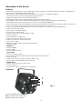
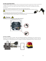
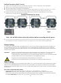
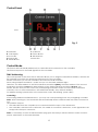
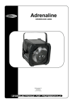
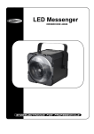
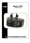
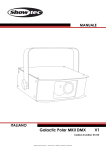
Dominator 3-in-1 Light effect ORDERCODE 43153 Highlite International B.V. Vestastraat 2 6468 EX Kerkrade The Netherlands Phone: +31 45-5667700 Congratulations! You have bought a great, innovative product from Showtec. The Showtec Dominator brings excitement to any venue. You can rely on Showtec, for more excellent lighting products. We design and manufacture professional light equipment for the entertainment industry. New products are being launched regularly. We work hard to keep you, our customer, satisfied. For more information: [email protected] You can get some of the best quality, best priced products on the market from Showtec. So next time, turn to Showtec for more great lighting equipment. Always get the best -- with Showtec ! Thank you! Showtec Showtec Dominator ™ Product Guide Warning ...............................................................................................................................................................................2 Safety Instructions .........................................................................................................................................................3 Laser safety for a Class 3B Laser Product .................................................................................................................5 Operating Determinations ..........................................................................................................................................6 Rigging ............................................................................................................................................................................6 Return Procedure ..........................................................................................................................................................7 Claims ..............................................................................................................................................................................7 Description of the device .................................................................................................................................................8 Overview ........................................................................................................................................................................8 Backside .........................................................................................................................................................................9 Installation ...........................................................................................................................................................................9 Set Up and Operation .....................................................................................................................................................10 Warning.........................................................................................................................................................................10 Control Modes .............................................................................................................................................................11 One Dominator (Automatic) ...............................................................................................................................11 One Dominator (Sound-control) .........................................................................................................................11 Multiple Dominators (Master/Slave control) .....................................................................................................11 Multiple Dominator (DMX Control) .....................................................................................................................12 Fixture Linking ...............................................................................................................................................................12 Data Cabling ...............................................................................................................................................................12 Control Panel ...............................................................................................................................................................13 Control Mode ..............................................................................................................................................................13 DMX Addressing ..........................................................................................................................................................13 Menu Overview ...........................................................................................................................................................14 Main Menu Options ....................................................................................................................................................15 1. DMX Mode ..........................................................................................................................................................15 2. Automatic Programs .........................................................................................................................................15 3. Sound-activated Programs ..............................................................................................................................16 4. Slave Mode .........................................................................................................................................................16 DMX Channels .............................................................................................................................................................16 9 Channels ...............................................................................................................................................................16 Maintenance ....................................................................................................................................................................19 Replacing a Fuse ........................................................................................................................................................19 Troubleshooting ...............................................................................................................................................................19 No Light .........................................................................................................................................................................19 No Response to DMX..................................................................................................................................................20 Product Specification .....................................................................................................................................................22 1 Warning FOR YOUR OWN SAFETY, PLEASE READ THIS USER MANUAL CAREFULLY BEFORE YOUR INITIAL START-UP! Unpacking Instructions Immediately upon receiving this product, carefully unpack the carton and check the contents to ensure that all parts are present, and have been received in good condition. Notify the dealer immediately and retain packing material for inspection if any parts appear damaged from shipping or the carton itself shows signs of mishandling. Save the carton and all packing materials. In the event that a fixture must be returned to the factory, it is important that the fixture be returned in the original factory box and packing. Your shipment includes: • Dominator with IEC powercable 1,75m • Remote plug and 2 keys • User manual CAUTION ! EYEDAMAGES !!! NEVER LOOK DIRECTLY INTO THE LIGHTSOURCE !!! NEVER PROJECT A SINGLE LASER POINT !!! CAUTION! Keep this device away from rain and moisture! Unplug mains lead before opening the housing! LED Expected Lifespan LEDs gradually decline in brightness over time. HEAT is the dominant factor that leads to the acceleration of this decline. Packaged in clusters, LEDs exhibit higher operating temperatures than in ideal or singular optimum conditions. For this reason when all color LEDs are used at their fullest intensity, life of the LEDs is significantly reduced. If improving your lifespan expectancy is of a higher priority, place care in providing for lower operational temperatures. This may include climatic-environmental and the reduction of overall projection intensity. 2 FOR YOUR OWN SAFETY, PLEASE READ THIS USER MANUAL CAREFULLY BEFORE YOUR INITIAL START-UP! Safety Instructions Every person involved with the installation, operation and maintenance of this device have to: be qualified follow the instructions of this manual CAUTION! Be careful with your operations. With a dangerous voltage you can suffer a dangerous electric shock when touching the wires! Before your initial start-up, please make sure that there is no damage caused by transportation. Should there be any, consult your dealer and do not use the device. To maintain perfect condition and to ensure a safe operation, it is absolutely necessary for the user to follow the safety instructions and warning notes written in this manual. Please consider that damages caused by manual modifications to the device are not subject to warranty. This device contains no user-serviceable parts. Refer servicing to qualified technicians only. IMPORTANT: The manufacturer will not accept liability for any resulting damages caused by the nonobservance of this manual or any unauthorized modification to the device. Never let the power-cord come into contact with other cables! Handle the power-cord and all connections with the mains with particular caution! Never remove warning or informative labels from the unit. Never use anything to cover the ground contact. Never leave any cables lying around. Do not insert objects into air vents. Do not connect this device to a dimmerpack. Do not open the device and do not modify the device. Do not point lasers at highly reflective surfaces such as windows, mirrors and shiny metal. Even laser reflections can be hazardous. Do not expose the output optic (aperture) to cleaning chemicals Do not use laser if the laser appears to be emitting only one or two beams Do not use laser if housing is damaged or open, or if optics appear damaged in any way. Do not operate laser without first reading and understanding all safety and technical data in this manual. Never look into the laser aperture or laser beams After set up and prior to public use, test laser to ensure proper function. Do not use the laser if any defect is detected. Do not use, if the laser emits only one or two laser beams rather than dozens/hundreds, as this could indicate damage to the diffraction grating optic, and could allow emission of higher laser levels. Never aim the laser beam at people or animals! Never use the device during thunderstorms, unplug the device immediately. Never look directly into the light source. Never point a laser at aircraft, this is a federal offense. Never point un-terminated laser beams into the sky. Never open the laser housing. The high laser power levels inside of the protective housing can start fires, burn skin and will cause instant eye injury. Never expose the lens to direct sunlight, not even for a short period. This may damage the light effect or even cause fire. Do not switch the device on and off in short intervals, as this would reduce the system’s life. Do not shake the device. Avoid brute force when installing or operating the device. Only use device indoor, avoid contact with water or other liquids. Only operate the fixture after having checked that the housing is firmly closed and all screws are tightly fastened. 3 Avoid flames and do not put close to flammable liquids or gases. Always check the regulations when using a class IIIB laser product. Always check and position the laser before anybody enters the room, when the laser is facing an area with people. Always allow free air space of at least 50 cm around the unit for ventilation. Always disconnect power from the mains, when device is not used or before cleaning! Only handle the power-cord by the plug. Never pull out the plug by tugging the power-cord. Make sure that the device is not exposed to extreme heat, moisture or dust. Make sure that the available voltage is not higher than stated on the rear panel. Make sure that the power-cord is never crimped or damaged. Check the device and the powercord from time to time. If the external cable is damaged, it has to be replaced by a qualified technician. If the lens is obviously damaged, it has to be replaced. So that its functions are not impaired, due to cracks or deep scratches. If device is dropped or struck, disconnect mains power supply immediately. Have a qualified engineer inspect for safety before operating. If the device has been exposed to drastic temperature fluctuation (e.g. after transportation), do not switch it on immediately. The arising condensation water might damage your device. Leave the device switched off until it has reached room temperature. If your Showtec device fails to work properly, discontinue use immediately. Pack the unit securely (preferably in the original packing material), and return it to your Showtec dealer for service. For adult use only. Laser effect must be installed out of the reach of children. Never leave the unit running unattended. For replacement use fuses of same type and rating only. The operation of a class 3B laser show laser is only allowed if the show is controlled by a skilled and well-trained operator familiar with the data included in this manual. The user is responsible for correct positioning and operating of the Dominator. The manufacturer will not accept liability for damages caused by the misuse or incorrect installation of this device. This device falls under protection class I. Therefore it is essential to connect the yellow/green conductor to earth. The laser will only work between 15-35ºC. After 3 hours working, you must shut off the laser and let the laser diode cool off for 30 minutes, otherwise the laser could be damaged and the warranty becomes void. Repairs, servicing and electric connection must be carried out by a qualified technician. WARRANTY: Till one year after date of purchase. Laser Light is different from any other light source with which you may be familiar. The light from this product can potentially cause instant eye injury if not set up and used properly. Laser light is thousands of times more concentrated than light from any other kind of light source. This concentration of light power can cause instant eye injuries, primarily by burning the retina (the light sensitive portion at the back of the eye). Even if you cannot feel “heat” from a laser beam, it can still potentially injure or blind you or your audience. Even very small amounts of laser light are potentially hazardous even at long distances. Laser eye injuries can happen quicker than you can blink. It is incorrect to think that because these laser products split the laser into hundreds of beams or the laser beam is scanned out in high speed, that an individual laser beam is safe for eye exposure. This laser product uses dozens of milliWatts of laser power (Class 3B levels internally). Many of the individual beams are potentially hazardous to the eyes. It is also incorrect to assume that because the laser light is moving, it is safe. This is not true. Nor, do the laser beams always move. Since eye injuries can occur instantly, it is critical to prevent the possibility of any direct eye exposure. According to the laser safety regulation, it is not legal to aim Class 3B lasers in areas which people can get exposed. This is true even if it is aimed below people’s faces, such as on a dance floor. 4 Laser safety for a Class 3B Laser Product CAUTION: AVOID EXPOSURE TO BEAM: Avoid direct eye contact with laser light. Never intentionally expose your eyes or others to direct laser radiation. Compliance Statement Your Dominator Laser has been designed to comply with FDA and IEC Standards for it classification. The Dominator is a Class IIIB laser product. Laser Safety and Compliance Information The Dominator is manufactured to comply with the IEC 60825-1 and in accordance with U.S. Food and Drug Administration (FDA) Standards Listed under FDA Document 21 CFR 1040 and subsequent laser notices. Product Classification and Manufacturing Label Identification Laser Classification: Class IIIB Cooling: TE Cooling Laser Power: 200mW (150mW 650nm Red, 50mW 532nm Green Beam Diameter <18mm at aperture Pulse Data All pulses < 4Hz (>0.25sec) Divergence (each beam) <2 mrad Divergence (total light) <160 degrees The legal requirements for using laser entertainment products vary from country to country. The user is responsible for the legal requirements at the location/country of use. Further guidelines and safety programs for safe use of lasers can be found in the ANSI Z136.1 Standard “For Safe Use of Lasers”, available from www.laserinstitute.org. Many local governments, corporations, agencies, military and others, require all lasers to be used under the guidelines of ANSI Z136.1. Laser Display guidance can be obtained via the International Laser Display Association, www.laserist.org. CAUTION: The use of corrective eye wear or optics for viewing at distances such as telescopes or binoculars within a distance of 100mm may pose an eye hazard. This laser product is a Class IIIB laser and has an Interlocked housing. There are no user serviceable parts inside. Tampering or removing warranty seals will void your products limited warranty. Combo label with the Product Model Number, Serial Number, Date of Manufacturing, Laser Light Warning Label, Warranty Void Label and Interlocked Housing Label 5 Proper Usage Safety and Compliance Information According to FDA Regulations you should operate this product as stated on the left. Operating Determinations • This device is not designed for permanent operation. Consistent operation breaks will ensure that the device will serve you for a long time without defects. • The minimum distance between light-output and the illuminated surface must be more than 0.5 meter. • The maximum ambient temperature ta = 35°C must never be exceeded. • The relative humidity must not exceed 50 % with an ambient temperature of 35° C. • If this device is operated in any other way, than the one described in this manual, the product may suffer damages and the warranty becomes void. • Any other operation may lead to dangers like short-circuit, burns, electric shock, crash, etc. You endanger your own safety and the safety of others! Rigging Please follow the European and national guidelines concerning rigging, trussing and all other safety issues. Do not attempt the installation yourself ! Always let the installation be carried out by an authorized dealer ! Procedure: If the Dominator is lowered from the ceiling or high joists, professional trussing systems have to be used. Use a clamp to mount the Dominator, with the mounting-bracket, to the trussing system. The Dominator must never be fixed swinging freely in the room. The installation must always be secured with a safety attachment, e.g. an appropriate safety net or safety-cable. When rigging, derigging or servicing the device, always make sure, that the area below the installation place is blocked and staying in the area is forbidden. Improper installation can cause serious damage to people and property ! 6 Connection with the mains Connect the device to the mains with the power-plug. Always pay attention, that the right color cable is connected to the right place. International EU Cable UK Cable US Cable Pin L BROWN RED YELLOW/COPPER FASE N BLUE BLACK SILVER NUL YELLOW/GREEN GREEN GREEN EARTH Make sure that the device is always connected properly to the earth! Return Procedure Returned merchandise must be sent prepaid and in the original packing, call tags will not be issued. Package must be clearly labeled with a Return Authorization Number (RMA number). Products returned without an RMA number will be refused. Highlite will not accept the returned goods or any responsibility. Call Highlite 0031-455667723 or mail [email protected] and request an RMA prior to shipping the fixture. Be prepared to provide the model number, serial number and a brief description of the cause for the return. Be sure to properly pack fixture, any shipping damage resulting from inadequate packaging is the customer’s responsibility. Highlite reserves the right to use its own discretion to repair or replace product(s). As a suggestion, proper UPS packing or double-boxing is always a safe method to use. Note: If you are given an RMA number, please include the following information on a piece of paper inside the box: 1) Your name 2) Your address 3) Your phone number 4) A brief description of the symptoms Claims The client has the obligation to check the delivered goods immediately upon delivery for any shortcomings and/or visible defects, or perform this check after our announcement that the goods are at their disposal. Damage incurred in shipping is the responsibility of the shipper; therefore the damage must be reported to the carrier upon receipt of merchandise. It is the customer's responsibility to notify and submit claims with the shipper in the event that a fixture is damaged due to shipping. Transportation damage has to be reported to us within one day after receipt of the delivery. Any return shipment has to be made post-paid at all times. Return shipments must be accompanied with a letter defining the reason for return shipment. Non-prepaid return shipments will be refused, unless otherwise agreed in writing. Complaints against us must be made known in writing or by fax within 10 working days after receipt of the invoice. After this period complaints will not be handled anymore. Complaints will only then be considered if the client has so far complied with all parts of the agreement, regardless of the agreement of which the obligation is resulting. 7 Description of the device Features The Showtec Dominator is a 3-in-1 light effect that combines 8 powerful white strobe LEDs, a 200mW RG laser module and 3Watt RGBWA LED effect. • All 3 effects can be selected separately in auto or music controlled programs. • The RG laser has many versatile grating & burst effects • Equipped with a key lock and remote interlock. • The strobe has 8 sections with different preprogrammed patterns. • All RGBWA colors can be selected individually or in many preprogrammed combinations. • Master/slave function can be used to create a synchronized lightshow. • Laser only works when the interlock connector is connected with a remote interlock (ordercode 51316). • You can test if the laser works properly with the included test connector. • If you use the laser in public area's an remote interlock is necessary for safety regulations. • LED, Laser & Strobe Effect • Power input: 100-240V 50/60z • Power consumption: 66W • Control: Auto, Sound, Master/Slave, DMX • DMX Channels: 9 • Control Display: 4 Digits LED • Power Connection: IEC in- & output • Data Connector: 3 pole XLR (In/Out) • Fuse 1,6 AL / 250V • Dimensions: 225 x 298 x 310mm (excl brackets) • Weight: 4,06kg LED effect • Colors: RGBWA • Power: 5x3W • Current: 300mA each Laser effect • Laser Color: Red, Green • Laser Power: 200mW (150mW 650nm Red, 50mW 532nm Green) • Laser Class: 3B • Safety Features: Key switch, Interlock, Safety eye • Laser Safety: EN/IEC 60825-1 Ed 2, 2007-03 Strobe effect • LED: 8x 1W White Power strobe LEDs • Current: 300mA • Accessories: 2 Keys, Interlock test connector Overview 1 2 3 Fig. 1 1) 3Watt RGBWA LED effect 2) 8 powerful white strobe LEDs 3) 200mW RG laser module 8 Backside 5 6 7 8 4 Fig. 2 9 10 11 12 4) Mountingbracket with adjustment screw 5) LCD Display + Menu Buttons 6) Audio Sensitivity and microphone 7) 3-pin DMX OUT 8) 3-pin DMX IN 13 9) Lock On/Off 10) IEC IN + Fuse 1 A/250V 11) Remote Control 12) IEC OUT 13) Safety Eye Installation Remove all packing materials from the Dominator. Check that all foam and plastic padding is removed. Connect all cables. Always disconnect from electric mains power supply before cleaning or servicing. Damages caused by non-observance are not subject to warranty. 9 Set Up and Operation Before plugging the unit in, always make sure that the power supply matches the product specification voltage. Do not attempt to operate a 120V specification product on 230V power, or vice versa. Connect the device to the main power supply. The device can be music-controlled by its built-in microphone. The Interlock plug/remote plug and safety keys are included in the box. The interlock is the “included-in-the-box” successor for the optional remote interlock (51316) They should be kept with the Dominator laser !!! The following safety precautions should be followed: -The interlock plug should be placed on the backside (11) of your Dominator laser. -The keys should be put into the lock (9) of your Dominator laser. Warning If the plug is not connected, your laser will not function. If the key is not set to ON, your laser will not function. Exclusion of liability Be aware that in some countries, there are additional regulations, regarding the use of laser devices. Therefore, we strongly advise you to verify your national laws with your authorities: We don’t take any responsibility for eventual discrepancies, changes or adaptions regarding lawful use of laser devices. 10 Control Modes There are 4 modes: • Automatic • Sound-controlled • Master/Slave • DMX512 One Dominator (Automatic) 1. Fasten the effect light onto firm trussing. Leave at least 0,5 meter on all sides for air circulation. 2. When the Dominator is not connected by a DMX-cable, it functions as a stand-alone device. Please see page 15 for more information about the Auto run visual effects. One Dominator (Sound-control) 1. Fasten the effect light onto firm trussing Leave at least 1 meter on all sides for air circulation. 2. Turn on the music. If the device is set to sound, then the Dominator will react to the beat of the music. Please see page 16 for more information about the sound-control options. Multiple Dominators (Master/Slave control) 1. Fasten the effect light onto firm trussing Leave at least 1 meter on all sides for air circulation. 2. Always use a safety cable (ordercode 70140 / 70141). 3. Use a 3-p XLR cable to connect the Dominator lasers. The pins: 1. Earth 2. Signal 3. Signal + 4. Link the units as shown in (Fig. 3), Connect a DMX signal cable from the first unit's DMX "out" socket to the second unit's "in" socket. Repeat this process to link the second, third, and fourth units. You can use the same functions on the master device as described on page 15+16 (Autorun or Music control). This means on the master device you can set your desired operation Mode and all slave devices will react the same as the master device. Multiple Dominators (Master/Slave control) Fig. 3 11 Multiple Dominator (DMX Control) 1. 2. 3. 4. Fasten the effect light onto firm trussing Leave at least 1 meter on all sides for air circulation. Always use a safety cable (ordercode 70140 / 70141). Use a 3-p XLR cable to connect the Dominator. Link the units as shown in (figure 4), Connect a DMX signal cable from the first unit's DMX "out" socket to the second unit's "in" socket. Repeat this process to link the second, third, and fourth units. 5. Supply electric power: Plug the end of the mains power cord into proper electric power supply sockets. Do so for all units and the controller. Multiple Dominators Pro Set Up Max. 30 Dominators Fig. 4 Note : Link all DMX cables and set dip switches before connecting electric power 6. Do not supply power before the whole system is set up and connected properly. Design your show according to your DMX controller functions. See page 13 for more about DMX programming. Fixture Linking You will need a serial data link to run light shows of one or more fixtures using a DMX-512 controller or to run synchronized shows on two or more fixtures set to a master/slave operating mode. The combined number of channels required by all the fixtures on a serial data link determines the number of fixtures the data link can support. Important: Fixtures on a serial data link must be daisy chained in one single line. To comply with the EIA-485 standard no more than 30 devices should be connected on one data link. Connecting more than 30 fixtures on one serial data link without the use of a DMX optically isolated splitter may result in deterioration of the digital DMX signal. Maximum recommended DMX data link distance: 100 meters Maximum recommended number of Dominators on a DMX data link: 30 fixtures Data Cabling To link fixtures together you must obtain data cables. You can purchase DAP Audio certified DMX cables directly from a dealer/distributor or construct your own cable. If you choose to create your own cable please use data-grade cables that can carry a high quality signal and are less prone to electromagnetic interference. DAP Audio Certified DMX Data Cables • DAP Audio Basic microphone cable for allround use. bal. XLR/M 3 p. > XLR/F 3 p. Ordercode FL01150 (1,5m.), FL013 (3m.), FL016 (6m.), FL0110 (10m.), FL0115 (15m.), FL0120 (20m.). • DAP Audio cable for the demanding user with exceptional audio-qualities and connector made by Neutrik®. Ordercode FL71150 (1,5m.), FL713 (3m.), FL716 (6m.), FL7110 (10m.). 12 Control Panel Fig. 5 A. DMX LED B. LCD Display C. Auto LED D. Sound LED E. MODE Button F. Up Button G. Down Button H. SETUP Button I. Slave LED Control Mode The fixtures are individually addressed on a data-link and connected to the controller. The fixtures respond to the DMX signal from the controller. DMX Addressing The control panel on the front side of the base allows you to assign the DMX fixture address, which is the first channel from which the Dominator will respond to the controller. Please note when you use the controller, the unit has max. 9 channels. When using multiple Dominator’s, make sure you set the DMX addresses right. Therefore, the DMX address of the first Dominator should be 1(d001); the DMX address of the second Dominator should be 1+9=10; the DMX address of the third Dominator should be 10+9=19, etc. Please, be sure that you don’t have any overlapping channels in order to control each Dominator correctly. If two or more Dominator’s are addressed similarly, they will work similarly. For address settings, please refer to the instructions under ”Addressing’ (menu d001) Controlling: After having addressed all Dominator’s, you may now start operating these via your lighting controller. Note: After switching on, the Dominator will automatically detect whether DMX 512 data is received or not. The problem may be: • The XLR cable from the controller is not connected with the input of the Dominator. • The controller is switched off or defective, the cable or connector is detective, or the signal wires are swapped in the input connector. Note: It’s necessary to insert a XLR termination plug (with 120 Ohm) in the last fixture in order to ensure proper transmission on the DMX data link. 13 Menu Overview The Dominator 3-in1 will only show its version number at start-up ! 14 Main Menu Options 1. DMX Channels 2. Automatic Programs 3. Sound-active Programs 4. Slave You can only change a certain setting when the display is blinking. If you can’t change a certain value, please press the MODE-button once and then change the value. 1. DMX Mode With this menu you can set the DMX address. 1) Press the FUNC button, until the display shows . 2) You can choose 506 different DMX addresses. Use the Up / Down buttons to select the required address from 3) Use the ENTER button to store your setting. . 2. Automatic Programs 1) Press the MODE button, until the display shows . 2) Use the Up / Down buttons to scroll through the entire menu. Laser + RGBWA + 8x White LEDs Laser + RGBWA Laser + 8x White LEDs RGBWA + 8x White LEDs RGBWA Laser 8x White LEDs 3) When you press the ENTER button in Auto Mode, you can set the speed of each automatic program. The speed can be set between . This is from slow to fasst 4) Use the ENTER button to store your setting. 15 3. Sound-activated Programs 1) Press the MODE button, until the display shows . 2) Use the Up / Down buttons to scroll through the entire menu. Laser + RGBWA + 8x White LEDs Laser + RGBWA Laser + 8x White LEDs RGBWA + 8x White LEDs RGBWA Laser 8x White LEDs 3) The device is music-controlled by its built-in microphone. The audio sensitivity control (6) allows you to adjust the sensitivity of the device. A clockwise movement increases the sensitivity 4) Use the ENTER button to store your setting. 4. Slave Mode With this menu you are able to set the device as a slave device. 1) Press the MODE button, until the display shows . 2) You can use the same functions on the master device. This means on the master device you can set your desired operation Mode and all slave devices will react the same as the master device 3) Use the ENTER button to store your setting. DMX Channels 9 Channels Channel 1 – Built-in Programs / Sound-controlled Mode 0-9 10-24 25-39 40-54 55-69 70-84 85-99 100-114 115-129 130-144 145-159 160-174 175-189 190-204 205-219 220-255 Blackout Auto 1 (Strobe, Derby, Laser) Auto 2 (Derby, Laser) Auto 3 (Strobe, Laser) Auto 4 (Derby, Laser) Auto 5 (Derby) Auto 6 (Laser) Auto 7 (Strobe) Sound 1 (Strobe, Derby, Laser) Sound 2 (Derby, Laser) Sound 3 (Strobe, Laser) Sound 4 (Derby, Laser) Sound 5 (Derby) Sound 6 (Laser) Sound 7 (Strobe) DMX Mode Only when CH1 is set between 220-255, CH2-CH9 will function 16 Channel 2 – Derby Colors (CH1 must set between 220-255 0-9 10-14 15-19 20-24 25-29 30-34 35-39 40-44 45-49 50-54 55-59 60-164 65-69 70-74 75-79 80-84 85-89 90-94 95-99 100-104 105-109 110-114 115-119 120-124 125-129 130-134 135-139 140-144 145-149 150-154 155-159 160-164 165-209 210-255 ) Blackout Red Green Blue Amber White White + Red Red + Green Green + Blue Blue + Amber Amber + White White + Green Green + Amber Amber + Red Red + Blue Blue + White Red + Green + Blue Red + Green + Amber Red + Green + White Red + Amber + Blue Red + Blue + White Red + Amber + White Amber + Green + Blue Green + Blue + White Amber + Green + White Amber + White + Blue Red + Green + Blue + Amber Red + Green + Blue + White Green + Blue + White + Amber Red + Green + White + Amber Red + Blue + White + Amber Red + Green + Blue + White + Amber Automatic (Single colors only) Automatic (Two colors only) Channel 3 – Derby Speed (CH1 must set between 220-255 and CH2 must be set between 10-255 0-255 ) From Slow to Fast Channel 4 – White LEDs Strobe (CH1 must set between 220-255 and CH2 must be set between 10-255) 0-6 7-254 255 Close Strobe from slow to fast Sound-activated strobe mode Channel 5 – White LEDs control (CH1 must set between 220-255 and CH4 must be set between 7-255) 0-9 10-19 20-29 30-39 40-49 50-59 60-69 70-79 80-89 90-99 100-109 110-255 Blackout Program 1 from fast to slow Program 2 from fast to slow Program 3 from fast to slow Program 4 from fast to slow Program 5 from fast to slow Program 6 from fast to slow Program 7 from fast to slow Program 8 from fast to slow Program 9 from fast to slow Program 10 from fast to slow Full On All 8 LEDs 17 Channel 6 – Laser (CH1 must set between 220-255 0-9 10-49 50-89 90-129 130-169 170-209 210-255 ) Blackout Red laser Green laser Red + Green laser strobe separately and after each other Green laser strobe + Red laser continuously ON Red laser strobe + Green laser continuously ON Red + Green laser strobe simultaneously Channel 7 – Laser Strobe (CH1 must set between 220-255 and CH6 must be set between 10-255) 0-4 5-254 255 Blackout Strobe from fast to slow Sound-activated strobe mode Channel 8 – Rotating Derby (CH1 must set between 220-255 and CH2 must be set between 10-255) 0-4 5-254 255 Stop Rotate clockwise from slow to fast Sound-activated strobe mode Channel 9 – Rotating Laser (CH1 must set between 220-255 and CH6 must be set between 10-255) 0-4 5-127 128-133 134-255 Stop Rotate clockwise from slow to fast Stop Rotate counter-clockwise from slow to fast 18 Maintenance The Showtec Dominator requires almost no maintenance. However, you should keep the unit clean. Otherwise, the fixture’s light-output will be significantly reduced. Disconnect the mains power supply, and then wipe the cover with a damp cloth. Do not immerse in liquid. Wipe lens clean with glass cleaner and a soft cloth. Do not use alcohol or solvents. Keep connections clean. Disconnect electric power, and then wipe the connections with a damp cloth. Make sure connections are thoroughly dry before linking equipment or supplying electric power. The operator has to make sure that safety-relating and machinetechnical installations are to be inspected by an expert after every four years in the course of an acceptance test. The operator has to make sure that safety-relating and machine-technical installations are to be inspected by a skilled person once a year. The following points have to be considered during the inspection: 1. All screws used for installing the device or parts of the device have to be tightly connected and must not be corroded. 2. There may not be any deformations on housings, fixations and installation spots. 3. Mechanically moving parts like axles, eyes and others may not show any traces of wearing. 4. The electric power supply cables must not show any damages or material fatigue. Replacing a Fuse Power surges, short-circuit or inappropriate electrical power supply may cause a fuse to burn out. If the fuse burns out, the product will not function whatsoever. If this happens, follow the directions below to do so. 1. Unplug the unit from electric power source. 2. Insert a screwdriver into the slot in the fuse cover. Gently pry up the fuse cover. The fuse will come out. 3. Remove the used fuse. If brown or unclear, it is burned out. 4. Insert the replacement fuse into the holder where the old fuse was. Reinsert the fuse cover. Be sure to use a fuse of the same type and specification. See the product specification label for details. Troubleshooting This troubleshooting guide is meant to help solve simple problems. If a problem occurs, carry out the steps below in sequence until a solution is found. Once the unit operates properly, do not carry out following steps. 1. If the device does not operate properly, unplug the device. 2. Check the power from the wall, the fuse, all cables etc. 3. If all of the above appears to be O.K., plug the unit in again. 4. If you are unable to determine the cause of the problem, do not open the Dominator, as this may damage the unit and the warranty will become void. 5. Return the machine to your Showtec dealer. No Light This troubleshooting guide is meant to help solve simple problems. If a problem occurs, carry out the steps below in sequence until a solution is found. Once the unit operates properly, do not carry out following steps. If the laser effect does not operate properly, refer servicing to a technician. Response: Suspect five potential problem areas: the power supply, the laser, the White LEDs, the Derby LEDs the fuse. 1. Power supply. Check that the unit is plugged into an appropriate power supply. 2. The laser, the White LEDS, the Derby LEDs. Return the device to your Showtec dealer. 3. The fuse. See page 19 for replacing the fuse. 19 No Response to DMX Response: Suspect the DMX cable or connectors, a controller malfunction, a light effect DMX card malfunction. 1. Check the DMX setting and the DMX polarity. Make sure that DMX addresses are correct. 2. If you have intermittent DMX signal problems, check the connector pins of the fixture or the previous one. 3. Check the DMX cable: Unplug the unit; change the DMX cable; then reconnect to electrical power. Try your DMX control again. 4. Check to see if the DMX cables run near or run alongside to high voltage cables that may cause damage or interference to DMX interface circuit. 5. Determine whether the controller or light effect is at fault. Does the controller operate properly with other DMX products ? If not, take the controller in for repair. If so, take the DMX cable and the light effect to a qualified technician. See below for more problem solving. The fixture does not work, no laser and the fan does not work 1. Check the connect power and main fuse. 2. Measure the mains voltage on the main connector. 3. Check the Power On indicated LED. The fixture is power on, but no laser coming out from aperture 1. Check the laser aperture cover. 2. Check the key switch. 3. Check the remote interlock or interlock connector. 4. Wait for at least 30 minutes to warm up in low temperature. 5. Check whether it is in music mode without sound signal. 6. Check whether it is in Slave mode. 7. Check whether it is in DMX without DMX signal. The laser effect power is very weak 1. Wait for at least 30 minutes to warm up in low temperature. 2. Clean the scanner mirror with alcohol. 3. Clean the aperture glass with alcohol. 4. Check whether it is in DMX with high strobe frequency. The laser is on, but the pattern is not moving 1. Check to see whether it is in Music/Sound mode without detecting sound signal. 2. Check to see whether it is in DMX mode with further DMX control. 3. Try to change the fixture to another stand-alone mode. 4. Try to control the fixture with DMX to see the laser effect system. 20 Problem One or more fixtures are completely dead. Fixtures reset correctly, but all respond erratically or not at all to the controller. Probable cause(s) No power to the fixture Remedy • Check that power is switched on and cables are plugged in. Primary fuse blown. • Replace fuse. The controller is not connected. 3-pin XLR Out of the controller does not match XLR Out of the first fixture on the link (i.e. signal is reversed). • Connect controller. • Install a phase reversing cable between the controller and the first fixture on the link. • Check data quality. If much lower than 100 percent, the problem may be a bad data link connection, poor quality or broken cables, missing termination plug, or a defective fixture disturbing the link. Poor data quality Bad data link connection Fixtures reset correctly, but some respond erratically or not at all to the controller. Data link not terminated with 120 Ohm termination plug. Incorrect addressing of the fixtures. One of the fixtures is defective and disturbs data transmission on the link. 3-pin XLR Out on the fixtures does not match (pins 2 and 3 reversed). No laser The power supply settings do not match local AC voltage and frequency. Laser damaged. 21 • Inspect connections and cables. Correct poor connections. Repair or replace damaged cables. • Insert termination plug in output jack of the last fixture on the link. • Check address setting. • Bypass one fixture at a time until normal operation is regained: unplug both connectors and connect them directly together. • Have the defective fixture serviced by a qualified technician. • Install a phase-reversing cable between the fixtures or swap pin 2 and 3 in the fixture, that behaves erratically. • Disconnect fixture. Check settings and correct if necessary. • Disconnect fixture. Check settings and correct if necessary. Product Specification Model: Showtec Dominator • All 3 effects can be selected separately in auto or music controlled programs. • The RG laser has many versatile grating & burst effects • Equipped with a key lock and remote interlock. • The strobe has 8 sections with different preprogrammed patterns. • All RGBWA colors can be selected individually or in many preprogrammed combinations. • Master/slave function can be used to create a synchronized lightshow. • Laser only works when the interlock connector is connected with a remote interlock (ordercode 51316). • You can test if the laser works properly with the included test connector. • If you use the laser in public area's an remote interlock is necessary for safety regulations. • LED, Laser & Strobe Effect • Power input: 100-240V 50/60z • Power consumption: 66W • Control: Auto, Sound, Master/Slave, DMX • DMX Channels: 9 • Control Display: 4 Digits LED • Power Connection: IEC in- & output • Data Connector: 3 pole XLR (In/Out) • Fuse 1,6 AL / 250V • Dimensions: 225 x 298 x 310mm (excl brackets) • Weight: 4,06kg LED effect • Colors: RGBWA • Power: 5x3W • Current: 300mA each Laser effect • Laser Color: Red, Green • Laser Class: 3B • Safety Features: Key switch, Interlock, Safety eye • Laser Safety: EN/IEC 60825-1 Ed 2, 2007-03 • Laser Power: 200mW (150mW 650nm Red, 50mW 532nm Green) Strobe effect • LED: 8x 1W White Power strobe LEDs • Current: 300mA • Accessories: 2 Keys, Interlock test connector Minimum distance: Minimum distance from flammable surfaces: 0.5m Minimum distance to lighted object: 0.8m Design and product specifications are subject to change without prior notice. Website: www.Showtec.info Email: [email protected] 22