1
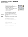
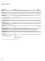
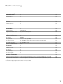
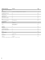
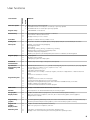
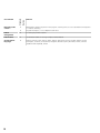
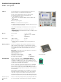
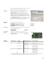
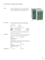
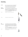
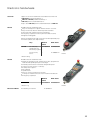
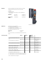
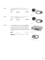
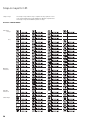
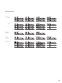
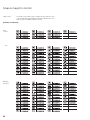
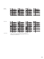
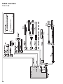
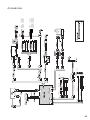
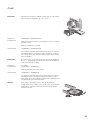
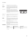
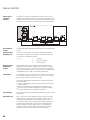
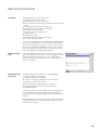
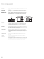
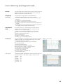
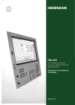
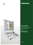
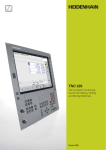
TNC 128 The Compact Straight-Cut Control for Milling, Drilling and Boring Machines Information for the Machine Tool Builder September 2015 TNC straight cut control from HEIDENHAIN General information TNC 128 • Straight cut control for milling, drilling and boring machines • Up to 5 axes and open-loop main spindle • Analog command interface to the drives (± 10 V) • Compact design: Screen, keyboard and main computer all in one unit • Dimensions: 400 mm x 450 mm x 91 mm • Integral 12.1-inch TFT color flat-panel display • Storage medium for NC programs: CompactFlash memory card • Programming in HEIDENHAIN conversational format • Standard milling, drilling and boring cycles • Touch probe cycles • Short block processing time System test Controls, motors and encoders from HEIDENHAIN are in most cases integrated as components in larger systems. In these cases, comprehensive tests of the complete system are required, irrespective of the specifications of the individual devices. Expendable parts In particular the following parts in controls from HEIDENHAIN are subject to wear: • Buffer battery • Fan Standards Standards (ISO, EN, etc.) apply only where explicitly stated in the catalog. Note Microsoft, Windows, Windows Vista and Internet Explorer are registered trademarks of Microsoft Corporation. Intel, Intel Core and Celeron are registered trademarks of Intel Corporation. Validity The features and specifications described here apply for the following control and NC software versions: TNC 128 with NC software version 771841-03 (no export license required) This catalog supersedes all previous editions, which thereby become invalid. Subject to change without notice. Requirements 2 Some of these specifications require particular machine configurations. Please note also that, for some functions, a special PLC program must be created by the manufacturer. Contents TNC straight cut control from HEIDENHAIN 2 Overview tables 4 Control components 12 Accessories 16 Cable overview 24 Technical description 26 Data transfer and communication 39 Mounting information 42 Overall dimensions 43 General information 52 Other HEIDENHAIN controls 54 Subject index 55 Please refer to the page references in the tables with the specifications. 3 Overview tables Overview of TNC 128 components Control system TNC 128 Page Main computer MC 128 12 Memory medium CFR CompactFlash memory card 12 NC software license On SIK component 12 Screen 12.1-inch color flat-panel display (integrated) Operating panel Integrated Machine operating panel Integrated 14 Encoder input board Necessary as of 4 axes and closed-loop spindle 13 Connecting cables ✓ 24 4 Accessories Accessories Electronic handwheels Workpiece touch probes Tool touch probes TNC 128 • HR 510 portable handwheel or • HR 520 portable handwheel with display or • HR 550 FS portable wireless handwheel with display or • HR 130 panel-mounted handwheel or • Up to three HR 150 panel-mounted handwheels via HRA 110 handwheel adapter • TS 2601) touch trigger probe with cable connection or • KT 130 edge finder with cable connection • TT 160 touch trigger probe Page 17 16 16 PLC input/output system For additional internal PLC inputs and outputs PL 510 consisting of PLB 51x basic module and I/O modules 15 USB hub ✓ 40 Snap-on keys For the control For handwheels 22 20 Accessories / Software TNC 128 Page PLCdesign1) PLC development software 36 KinematicsDesign1) Software for kinematic configuration 31 TNCremo2) Data transfer software 40 TNCremoPlus2) Data transfer software with “live” screen 40 ConfigDesign1) Software for configuring the machine parameters 33 CycleDesign1) Software for creating cycle structures 38 TNCkeygen1) Software for enabling SIK options for a limited time, and for day-by-day access to the OEM area 12 TNCscope1) Software for data recording 34 TeleService1) Software for remote diagnostics, monitoring, and operation 34 RemoTools SDK1) Function library for developing customized applications for communication with HEIDENHAIN controls 41 TNCtest1) Software for creation and execution of acceptance tests - 1) 1) 2) New generation of touch probes Available to registered customers for downloading from the Internet Available to all customers (without registration) for downloading from the Internet 5 Specifications Specifications TNC 128 Page Axes 3 closed-loop axes, optional: 4th and 5th axis 27 PLC axes ✓ 27 Central drive ✓ 27 Open-loop axes ✓ 27 Main spindle Max. 2; second spindle can be controlled alternately with the first Analog nominal speed value Up to 100 000 rpm Digital control over PLC outputs ✓ Position-controlled spindle ✓ 28 Oriented spindle stop ✓ 28 Gear shifting ✓ 28 NC program memory 1.8 GB 28 Input resolution and display step Linear axes 1 μm 27 Rotary axes 0.001° 27 Axis feedback control Analog speed command interface ± 10 V (X8) 30 With following error ✓ With feedforward ✓ Cycle times Block processing 6 ms Path interpolation 3 ms Permissible temperature range Operation: In electrical cabinet: 5 °C to 40 °C In operating panel: 0 °C to 50 °C Storage: –20 °C to 60 °C * 6 For further information, refer to the brochure TNC 128 Machine interfacing Machine interfacing TNC 128 Page Error compensation ✓ 32 Linear axis error ✓ 32 Nonlinear axis error ✓ 32 Backlash ✓ 32 Hysteresis ✓ 32 Thermal expansion ✓ 32 Static friction ✓ 32 Sliding friction ✓ 32 Integrated PLC ✓ 35 Program format Statement list 35 Program input at the control By external USB keyboard 35 Program input by PC ✓ 35 Symbolic PLC-NC interface ✓ 35 PLC memory 350 MB 35 PLC cycle time 9 ms to 30 ms (adjustable) 35 PLC inputs, 24 V DC 31 (expandable via PL); additional 25 on machine operating panel 15 PLC outputs, 24 V DC 31 (expandable by PL) 15 Inputs for PT 100 thermistors Via PL 15 PLC functions ✓ 35 Small PLC window ✓ 35 PLC soft keys ✓ 35 PLC positioning ✓ 36 PLC basic program ✓ 37 Integration of applications 36 High-level language programming Python programming language used in combination with the PLC (option 46) 36 User interfaces can be customdesigned 36 1) Inclusion of specific user interfaces from the machine tool builder (option 46) Further PLC inputs/outputs over PL 510 for connection to MC 7 Machine interfacing TNC 128 Commissioning and diagnostic aids Page 33 ConfigDesign Software for creating the machine configuration 33 Integrated oscilloscope ✓ 33 Trace function ✓ 34 API DATA function ✓ 34 Table function ✓ 34 OnLine Monitor (OLM) ✓ 33 Log ✓ 34 Commissioning wizard For analog axes 33 Data interfaces ✓ Ethernet 1000BASE-T 39 USB Rear: 2 x USB 3.0 Front: USB 2.0 39 RS-232-C ✓ 39 Protocols 39 Standard data transfer ✓ 39 Blockwise data transfer ✓ 39 LSV2 ✓ 39 Encoder inputs 29 Position 4 (optional: 5) 29 Incremental 1 VPP 29 absolute EnDat 2.1 29 1) 8 Further PLC inputs/outputs over PL 510 for connection to MC Short description TNC 128 Option User function Standard User functions ✓ 0 1 Basic version: 3 axes plus spindle 1st additional axis for 4 axes plus closed-loop or open-loop spindle 2nd additional axis for 5 axes plus open-loop spindle Program entry ✓ HEIDENHAIN conversational Position entry ✓ ✓ ✓ Nominal positions for lines in Cartesian coordinates Incremental or absolute dimensions Display and entry in mm or inches Tool tables ✓ Multiple tool tables with any number of tools Cutting data ✓ Automatic calculation of spindle speed, cutting speed, feed per tooth and feed per revolution Fixed cycles ✓ ✓ ✓ ✓ ✓ ✓ ✓ Drilling, conventional and rigid tapping Rectangular pockets Face milling Peck drilling, reaming, boring, counterboring, centering Multioperation machining of rectangular pockets Cartesian and polar point patterns OEM cycles (special cycles developed by the machine tool builder) can be integrated Program jumps ✓ ✓ ✓ Subprograms Program section repeats Calling any program as a subprogram Coordinate transformation ✓ Datum shift, mirror image, scaling factor (axis-specific) Q parameters Programming with variables ✓ Mathematical functions =, +, –, *, /, sin α, cos α, tan α, arc sin, arc cos, arc tan, an, en, ln, log, angle α of sin α and cos α, square root of a, square root of (a2 + b2) Logical operations (=, = /, <, >) Calculating with parentheses Absolute value of a number, constant π, negation, truncation of digits before or after the decimal point Functions for calculation of circles Programming aids ✓ ✓ ✓ ✓ ✓ ✓ Calculator Complete list of all current error messages Context-sensitive help function for error messages TNCguide: The integrated help system. User information available directly on the TNC Graphic support for programming cycles Comment and structure blocks in the NC program CAD viewer ✓ Display of standardized CAD data formats on the TNC Teach-In ✓ Actual positions can be transferred directly into the NC program Test graphics Display modes ✓ ✓ Graphic simulation before a program run, even while another program is running Plan view / projection in 3 planes / 3-D view, also in tilted working plane / 3-D line graphics Magnification of details ✓ ✓ ✓ ✓ ✓ Programming graphics ✓ In the Programming and Editing mode, the contour of the NC blocks is drawn on screen while they are being entered (2-D pencil-trace graphics), even while another program is running Program-run graphics Display modes ✓ ✓ Graphic simulation during real-time machining Plan view / projection in 3 planes / 3-D view Machining time ✓ ✓ Calculation of machining time in the Test Run operating mode Display of the current machining time in the Program Run operating modes 9 TNC 128 Option Standard User function Returning to the contour ✓ ✓ Mid-program startup in any block in the program, returning the tool to the calculated nominal position to continue machining Program interruption, contour departure and return Datum management ✓ For saving any reference points Datum tables ✓ Several datum tables for storing workpiece-related datums Conversational languages ✓ English, German, Czech, French, Italian, Spanish, Portuguese, Dutch, Swedish, Danish, Finnish, Norwegian, Slovenian, Slovak, Polish, Hungarian, Russian (Cyrillic), Romanian, Turkish, Chinese (traditional and simplified), Korean 10 Options Option number Option As of NC software 771841- ID Remark Page 0 Additional Axis 1 01 ID 354540-01 Additional control loop 1 1 Additional Axis 2 01 ID 353904-01 Additional control loop 2 17 Touch probe functions 01 ID 634063-01 Touch probe cycles • Reference-point setting • Tool and workpiece measurement • Touch probe input enabled for non-HEIDENHAIN systems 38 18 HEIDENHAIN DNC 01 ID 526451-01 Communication with external PC applications over COM component 41 46 Python OEM process 01 ID 579650-01 Execute Python applications 36 11 Control components Main computer TNC 128 The standard version of the TNC 128 features four inputs for position encoders. It can be enhanced with options. The TNC 128 includes the MC 128 main computer with: • Intel Celeron 1047 processor (1.4 GHz, dual-core) • 2 GB SDRAM main memory • 12.1-inch TFT color flat-panel display; resolution 1024 x 768 pixels • TNC keyboard • Machine operating panel • PLC • Interface to handwheel and touch probes • Further interfaces (PLC expansion, Ethernet, USB 2.0 on front, 2 x USB 3.0 on rear, RS-232-C/V.24 To be ordered separately, and installed in the main computer by the OEM: • CFR CompactFlash memory card with the NC software • SIK component (System Identification Key) for enabling control loops and options MC 128 Position inputs Mass Power supply Supply voltage1) Power consumption 1) Memory medium 4 x 1 VPP or EnDat (optional 5 x 1 VPP or EnDat) 8 kg ID 803344-xx 24 V DC 60 W PELV according to EN 61800-5-1 for low voltage electrical separation A CFR (= CompactFlash Removable) compact flash memory card is used as storage medium. It contains the NC software and is used to store NC and PLC programs. The storage medium is removable and must be ordered separately from the main computer. Please note: These CFRs use the fast SATA protocol (CFast) for significantly shorter access times. CFR CompactFlash 8 GB Free capacity for NC programs Free capacity for PLC programs No export license required SIK component 1.8 GB 350 MB ID 1038498-53 The SIK component contains the NC software license for enabling control loops and software options. It gives the main computer an unambiguous ID code—the SIK number. The SIK component is ordered and shipped separately. It must be inserted in a special slot in the MC main computer. The SIK component with the NC software license is available in various versions, depending on the enabled control loops and options. Further control loops can be enabled later by entering a keyword. HEIDENHAIN provides the keyword, which is based on the SIK number. When ordering, please indicate the SIK number of your control. When the keywords are entered in the control, they are saved in the SIK component. This enables and activates the options. Should service become necessary, the SIK component must be inserted in the replacement control to enable all required options. Master keyword (general key) 12 CFR CompactFlash There is a master keyword (general key) for putting the TNC 128 into service that will unlock all options for a duration of 90 days. SIK component After this period, only those options with the correct keywords will be active. The general key is activated via a soft key. TNCkeygen (accessory) TNCkeygen is a collection of PC software tools for generating time-limited enabling keys for HEIDENHAIN controls. OEM Key Generator is used to generate enabling keys for software options by entering the SIK number, the option to be enabled, the duration and a manufacturer-specific password. The enabling period is limited to 10 to 90 days. Each option can only be enabled once. Option enabling is independent of the general key. The OEM daily key generator generates an enabling key for the protected area of the machine tool builder. This grants the operator access to the area on the day the key was generated. NC software license SIK with software license and enabling for 4 control loops (3 axes and closed-loop spindle) 4 control loops and option 17 (Touch Probe) 5 control loops (4 axes and closed-loop spindle) 6 control loops (5 axes and open-loop spindle) Axis options With the NC software license for three axes, two additional control loops can be enabled retroactively: 1st additional axis 2nd additional axis Encoder input board ID 354540-01 ID 353904-01 An additional encoder input board is required for axis configurations with four or more axes plus closed-loop spindle. Encoder input board Possible configurations ID 822102-51 ID 822102-55 ID 822102-52 ID 822102-53 ID 554296-xx Closed-loop axes Spindle1) NC software license for Necessary options 3 Closed loop 4 control loops – 4 Open loop 4 control loops 1st additional axis 5 control loops – 4 control loops 1st additional axis Encoder input board 5 control loops Encoder input board 4 control loops 1st additional axis 2nd additional axis Encoder input board 5 control loops 2nd additional axis Encoder input board 4 5 1) Closed loop Open loop For the open-loop spindle, the TNC commands an analog nominal speed value for the spindle speed. For the closed-loop spindle, position feedback is provided, for example for oriented spindle stop. 13 Options The capabilities of the TNC 128 can also be adapted retroactively with options to meet new requirements. These options are described on page 11. They are enabled by entering keywords based on the SIK number, and are saved in the SIK component. Please indicate your SIK number when ordering new options. TNC keyboard The keys for the axes Z, 4 and 5 are designed as snap-on keys and can be replaced by keys with other symbols (see Snap-on keys). Export license An export license is generally not required for the TNC 128. Machine operating panel The TNC 128 features an integrated machine operating panel. • 24 snap-on keys, which can be addressed directly via the PLC, 3 snap-on keys can be wired as desired • Operating elements (pre-assigned according to PLC basic program): Control voltage on1); Emergency stop, NC start1); NC stop1); 4 axis keys; rapid traverse; unlock door; spindle start; spindle stop; coolant; rinse-water jet; chip removal (for other key symbols, see Snap-on keys) • Additional connections: Terminals for 8 PLC outputs (defaults pre-assigned) 1) 14 Keys illuminated, addressable via PLC PL 510 PLC input/output system PL 510 If the PLC inputs/outputs of the control do not suffice, additional PL 51x PLC input/output systems can be connected. These external modular I/O systems consist of a PLB 51x basic module and one or more PLD 16-8 and PLA 4-4 input/output modules. PL 510 Basic modules Basic modules feature slots for 4, 6 or 8 I/O modules. They are mounted on standard NS 35 rails (DIN 46 227 or EN 50 022). Supply voltage Power consumption Mass 24 V DC ≈ 20 W 0.36 kg (bare) Basic modules with HEIDENHAIN PLC interface PLB 510 Slots for 4 I/O modules PLB 511 Slots for 6 I/O modules PLB 512 Slots for 8 I/O modules ID 358849-01 ID 556941-01 ID 557125-01 Up to four PLB 510 modules, and up to two PLB 511 or PLB 512 modules can be connected to the control. The maximum cable length to the last PLB 51x is 30 m. I/O modules The I/O modules consist of one module with digital inputs/outputs and one analog module. For partially occupied basic modules, the unused slots must be occupied by an empty housing. PLD 16-8 ID 360916-11 I/O module for PL 5x0 with 16 digital inputs and 8 digital outputs. The maximum power output per module is 200 W. A load of up to 2 A can be placed on each output. No more than four outputs may be loaded with 2 A at any given time. Mass 0.2 kg PLA 4-4 ID 366423-01 Analog module for PL 5x0 with 4 analog inputs for PT 100 thermistors 4 analog inputs for ± 10 V Mass 0.2 kg Empty housing For unused slots ID 383022-xx 15 Accessories Touch probes Overview Before the TNC 128 leaves the factory, it is already prepared for the use of touch probes for workpiece or tool measurement. These touch probes generate a trigger signal that saves the current position value to the NC. For more information on the touch probes, ask for our brochure titled Touch Probes Workpiece measurement The TS touch trigger probes and the KT edge finders have a stylus for probing workpieces. The HEIDENHAIN controls provide standard routines for datum setting and workpiece measurement and alignment. The touch probes are available with various taper shanks. Assorted styli are available as accessories. Touch probes with cable connection for signal transmission for machines with manual tool change: KT 130 Edge finder for manual and controlled machines KT 130 TS 260 New generation touch probe for NC machines TS 260 Tool measurement The touch probes for tool measurement from HEIDENHAIN are suited for probing stationary or rotating tools directly on the machine. The TNC 128 has standard routines for measuring the length and diameter of the tool as well as the individual teeth. The TNC 128 automatically saves the results of measurement in a tool table. It is also possible to measure tool wear between two machining steps. With the triggering TT touch probes, the disk-type probe contact is deflected from its rest position upon contact with a stationary or rotating tool, sending a trigger signal to the TNC 128 control. TT 160 New generation touch probe; signal transmission to the control over connecting cable TT 160 16 Electronic handwheels Overview Support of electronic handwheels is standard on the TNC 128. • HR 550 FS wireless handwheel, or • HR 510 or HR 520 portable handwheel, or • HR 130 panel-mounted handwheel or • Up to three HR 150 panel-mounted handwheels via HRA 110 HR 510 Portable electronic handwheel with • Keys for actual-position capture and the selection of 5 axes • Keys for traverse direction and three preset feed rates • Three keys with machine functions (see below) • Emergency stop button and two permissive buttons (24 V) • Magnetic holding pads All keys are designed as snap-on keys and can be replaced by keys with other symbols (see Snap-on keys). Keys HR 510 Without detent With detent NC start/stop, ID 1119971-xx ID 1120313-xx spindle start (for PLC basic program) FCT A, FCT B, FCT C – ID 1099897-xx HR 510 Mass ≈ 0.6 kg HR 520 Portable electronic handwheel with • Display for operating mode, actual position value, programmed feed rate and spindle speed, error messages • Override potentiometer for feed rate and spindle speed • Selection of axes via keys or soft keys • Actual position capture • NC start/stop • Spindle on/off • Keys for continuous traverse of the axes • Soft keys for machine functions of the machine manufacturer • Emergency stop button HR 520 Without detent With detent ID 670302-xx ID 670303-xx Mass ≈ 1 kg Mount for HR 520 For fastening on machine HR 520 ID 591065-xx 17 HR 550 FS Electronic handwheel with wireless transmission. Display, operating elements and functions same as HR 520. In addition: • Functional safety • Wireless transmission range up to 20 m (depending on environment) HR 550 FS W/o detent With detent ID 598515-xx ID 606622-xx Replacement battery for HR 550 FS ID 623166-xx HR 550 FS with HRA 551 FS HRA 551 FS Handwheel mount for HR 550 FS • For docking the HR 550 FS on the machine • Integrated charger for HR 550 FS • Connections to the control and the machine • Integrated transmitter/receiver unit HRA 551 FS Mass ID 731928-xx ≈ 1.0 kg For more information, see the HR 550 FS Product Information sheet. Connecting cables HR 510 HR 520 HR 550 FS with HRA 551 FS Connecting cable (spiral cable) to HR (3 m) – ✓ – ID 312879-01 ✓ – – ID1117852-03 Connecting cable with metal armor – ✓ – ID 296687-xx ✓ – – ID 1117855-xx Connecting cable without metal armor – ✓ – ID 296467-xx ✓ – – ID 1117853-xx Adapter cable for HR/HRA to MC ✓ ✓ ✓1) ID 296466-xx Extension cable to adapter cable ✓ ✓ ✓1) ID 281429-xx Adapter cable for HRA to MC – – ✓2) ID 749368-xx – – ✓2) ID 749369-xx Dummy plug for standard handwheels ✓ ✓ – ID 271958-03 Dummy plug for handwheels with FS – – ID 271958-05 Extension cable to adapter cable 1) 2) For cable lengths up to 20 m between MB and HRA 551 FS For cable lengths up to 50 m between MB and HRA 551 FS See also Cable overview on Page 24. 18 – HR 130 Panel-mounted handwheel with ergonomic control knob. It is attached to the MB 7x0 or the TE 7x5 either directly or via an extension cable. HR 130 Mass W/o detent With detent ≈ 0.7 kg ID 540940-03 ID 540940-01 HR 130 HR 150 Panel-mounted handwheel with ergonomic control knob for connection to the HRA 110 handwheel adapter. HR 150 Mass W/o detent With detent ≈ 0.7 kg ID 540940-07 ID 540940-06 HR 150 HRA 110 Handwheel adapter for connection of up to three HR 150 panelmounted handwheels and two switches for axis selection and for selecting the subdivision factor. The first two handwheels are permanently assigned to axes 1 and 2. The third handwheel is assigned to the axes over a selection switch (accessory) or by machine parameters. The position of the second selection switch (accessory) is evaluated by the PLC, for example to set the proper interpolation. HRA 110 Mass Handwheel selection switch ≈ 1.5 kg ID 261097-xx HRA 110 With turning knob and cable ID 270908-xx Handwheel selection switch 19 Snap-on keys for HR Snap-on keys The snap-on keys make it easy to replace the key symbols. In this way, the HR handwheel can be adapted to different requirements. The snap-on keys are available in packs of 5 keys. Overview of HR 520/HR 550 Axis keys Orange Gray Machine functions Spindle functions Other keys 20 Overview of HR 510 Axis keys Orange Gray Machine functions Black Green Spindle functions Other keys Black Red Green Green Red 21 Snap-on keys for control Snap-on keys The snap-on keys make it easy to replace the key symbols. In this way, the keyboard can be adapted to different requirements. The snap-on keys are available in packs of 5 keys. Overview of control keys Keys Orange Gray Machine functions Black Green Black Red Black Black 22 Red Spindle functions Green Green Red Black Other keys Black Red ID 679843-F4 Orange Black ID 679843-F5 Black ID 679843-F6 Green Special keys Red Snap-on keys with customized symbols for special applications can also be manufactured. The laser labeling differs optically from the labeling of the standard keys. 23 TNC 128 15.05.2014 Cable overview TNC 128 24 1070793-xx 747400-xx 1070793-xx upon request TS 260 Adapter 15 pin 660042-xx 368330-xx 368330-xx 745454-xx 745454-xx 274543-xx X26 (Ethernet) TT 160 296466-xx 1117855-xx 1117853-xx 1117852-03 296687-xx 296467-xx 312879-01 3m 3m HR 510 FS 1119974-xx 1120311-xx 1120314-xx HR 520 FS 670304-xx 670305-xx 03.07.2015 HR 510 1119971-xx 1120313-xx 1099897-xx HR 520 670302-xx 670303-xx Accessories 25 Technical description Operating system HEROS 5 26 The TNC 128 runs HEROS 5 (HEIDENHAIN Real-time Operating System). This future-focused operating system features powerful functions: • Display of PDF files. Drawings, work instructions, etc. can be opened directly on the control. • Direct Internet access from the TNC 128 thanks to the integrated browser. The browser can be run in a Sandbox to increase data security. • Plays audio and video files (ogg) • You can open various file formats directly on the TNC 128 and also edit some of them with the appropriate editors: – Text files (.txt, .ini) – Graphic files (.gif, .bmp, .jpg, .png) – Tables (.xls, .csv) – Internet files (.html) • Standardized display format for operating system dialogs • Setting up a firewall for additional data security Axes Linear axes Depending on the options enabled, the TNC 128 can control linear axes with any axis designation (X, Y, Z, U, V, W ...). Display and programming –99 999.999 to +99 999.999 [mm] Feed rate in mm/min relative to the workpiece contour, or mm per spindle revolution Feed rate override: 0 % to 150 % Traverse range –99 999.999 to +99 999.999 [mm] The machine tool builder defines the traverse range. The user can set additional limits to the traverse range if he wishes to reduce the working space. Three different traverse ranges can be defined (selection by PLC). Rotary axes The TNC 128 can control a rotary axis with any axis designation (A, B, C, U ...). Special parameters and PLC functions are available for rotary axes with Hirth coupling. Display and programming 0° to 360° or –99 999.999 to +99 999.999 [°] Feed rate in degrees per minute [°/min] Traverse range –99 999.999 to +99 999.999 [°] The machine tool builder defines the traverse range. The user can set additional limits to the traverse range if he wishes to reduce the working space. Various traverse ranges can be defined per axis using parameter sets (selection by PLC). PLC axes Axes can be controlled by the PLC. They are programmed through M functions or OEM cycles. The PLC axes are positioned independently of the NC axes and are therefore designated as asynchronous axes. 27 Spindle Analog nominal speed value Up to 100000 min-1 Positioncontrolled spindle The position of the spindle is monitored by the control. Encoder HEIDENHAIN rotary encoder with sinusoidal voltage signals (1 VPP) or EnDat interface. Tapping There are special cycles for tapping with or without floating tap holder. For tapping without floating tap holder, the spindle must be operated under position control. Oriented spindle stop With a position-controlled spindle, the spindle can be positioned exactly to 0.1°. Spindle override 0 to 150 % Gear ranges A separate nominal speed is defined for each of the gear ranges. The gear stages are controlled by the PLC. Second spindle Up to two spindles can be alternately controlled. You can switch from spindle 1 to spindle 2 through the PLC. Because the second spindle is controlled instead of an axis, the number of available axes is reduced by one. 28 Encoders Overview For speed and position control of the axes and spindle, HEIDENHAIN offers both incremental and absolute encoders. Incremental encoders Incremental encoders have as measuring standard a grating consisting of alternate lines and spaces. Relative movement between the scanning head and the scale causes output of sinusoidal scanning signals. The measured value is calculated from these signals. Reference mark When the machine is switched on, the machine axes need to traverse a reference mark for an accurate reference to be established between measured value and machine position. For encoders with distance-coded reference marks, the maximum travel until automatic reference mark evaluation for linear encoders is only 20 mm or 80 mm, depending on the model, or 10° or 20° for angle encoders. Evaluation of reference marks The routine for traversing the reference marks can also be started for specific axes via the PLC during operation (reactivation of parked axes). Output signals Incremental encoders with sinusoidal output signals with ~ 1 VPP levels are suitable for connection to HEIDENHAIN numerical controls. Absolute encoders With absolute encoders, the position information is contained in several coded tracks. Thus, an absolute reference is available immediately after switch-on. Reference-mark traverse is not necessary. Additional incremental signals are output for highly dynamic control loops. EnDat interface The TNC 128 features the serial EnDat 2.1 interface for the connection of absolute encoders. Note: The EnDat interface on HEIDENHAIN encoders differs in its pin assignment from the interface on Siemens motors with integrated absolute ECN/EQN rotary encoders. Special adapter cables are available. Encoder inputs for position control Incremental and absolute linear, angular or rotary encoders from HEIDENHAIN can be connected to encoder inputs of the TNC 128. Channel inputs Signal level/Interface1) Input frequency1) Incremental ~1 VPP 33 kHz/350 kHz Absolute EnDat 2.1 ~1 VPP – 33 kHz/350 kHz 1) Switchable 29 Servo control Analog speed command interface The position controller is integrated in the TNC 128. The motor speed controller and the current controller are located in the servo amplifier. The TNC transmits the speed command signal through an analog ± 10 V interface (connection X8) to the servo amplifier. Axis feedback control The TNC 128 can be operated with following error or feedforward control. Operation with following error The term “following error” denotes the distance between the momentary nominal position and the actual position of the axis. The velocity is calculated as follows: v = kv · sa v kv sa = velocity = position loop gain = following error Operation with feedforward control Feedforward means that the speed and the acceleration are adjusted to fit the machine. Together with the values calculated from the following error, it forms the nominal value. This greatly reduces the following error (to within a few µm). The feedforward is adjustable from 0 to 100 % via a machine parameter. Central drive It is possible to use one common drive for several or all machine axes. The NC software allows the user to use the same nominal position value output for more than one axis. The most important basic requirements for realizing a machine with central drive: • Common drive package with an analog nominal position value input for all axes. • The PLC must handle the machine axes as clamping axes. • The PLC monitors the drive regarding movement in multiple axes and outputs an error message if necessary. Axis clamping The control loop can be opened through the PLC in order to clamp specific axes. Open-loop axes One or more axes can be defined as open-loop axes (manually operated axes, counter axes). They have position encoders for determining and displaying the current position value, but no nominal-value outputs. The target position is approached by the machine operator manually (e.g. via mechanical handwheels). When an NC block with an open-loop axis is reached during machining, a dialog window appears, prompting the machine operator to traverse the axis to the nominal coordinates. 30 Monitoring functions Description During operation the control monitors the: • Amplitude of the encoder signals • Edge separation of the encoder signals • Absolute position from encoders with distance-coded reference marks • Current position (following error monitoring) • Actual path traversed (movement monitoring) • Position deviation at standstill • Checksum of safety-related functions • Supply voltage • Buffer battery voltage • Operating temperature of the MC and CPU • Run time of the PLC program In the case of hazardous errors, an EMERGENCY STOP message is sent to the external electronics via the control-is-ready output, and the axes are brought to a stop. The correct connection of the TNC 128 in the machine’s EMERGENCY STOP loop is checked when the control system is switched on. In the event of an error, the control displays a message in plain language. Context-sensitive help The HELP and ERR keys provide the user with context-sensitive help. This means that in the event of an error message, the control displays information on the cause of the error and proposes solutions. The machine tool builder can also use this function for PLC error messages. KinematicsDesign (accessory) KinematicsDesign is a PC program for creating adaptable kinematic configurations. It supports: • Complete kinematic configurations • Transfer of configuration files between control and PC • Description of tool-carrier kinematics Kinematics descriptions developed for the iTNC 530 can also be converted to kinematics descriptions for the TNC 640/620/320/128. If KinematicsDesign is connected with a control online (operation is also possible with the programming station software), then machine movements can be simulated graphically along with axis traverse. Possible display views include a wire model or a pure listing of the transformation chain. The TNC 640 and iTNC 530 can also depict the entire work envelope. 31 Error compensation Overview The TNC 128 automatically compensates mechanical errors on the machine. Linear error Linear error can be compensated over the entire travel range for each axis. Nonlinear error The TNC 128 can compensate for ball-screw pitch errors and sag errors simultaneously. The compensation values are stored in a table. Backlash The play between table movement and rotary encoder movement on direction changes can be compensated in length measurements by spindle and rotary encoder. This backlash is outside the controlled system. Hysteresis The hysteresis between table movement and motor movement is also compensated in direct length measurements. In this case the hysteresis is within the controlled system. Static friction At very low feed rates, high static friction can cause the slide to stop and start repeatedly for short periods. This is commonly known as stick-slip. The TNC 128 can compensate for this problem condition. Sliding friction Sliding friction is compensated by the speed controller of the TNC 128. Thermal expansion To compensate thermal expansion, the machine’s expansion behavior must be known. The temperature can be recorded via thermistors connected to the analog inputs of the TNC 128. The PLC evaluates the temperature information and transfers the compensation value to the NC. 32 Commissioning and diagnostic aids Overview The TNC 128 provides comprehensive internal commissioning and diagnostic aids. It also includes highly effective PC software for diagnosis, optimization and remote control. ConfigDesign (accessory) PC software for configuring the machine parameters • Machine-parameter editor for the control; all support information; additional data and input limits are shown for each parameter • Configuration of machine parameters • Comparison of parameters from different controls • Importing of service files: easy testing of machine parameters in the field • Rule-based creation and management of machine configurations for multiple controls (together with PLCdesign) Online Monitor (OLM) The online monitor is a component part of the TNC 128 and is called over a code number. It supports commissioning and diagnosis of control components by: • Display of control-internal variables for axes and channels • Display of controller-internal variables (if a CC is present) • Display of hardware signal states • Various trace functions • Activation of spindle commands • Enabling control-internal debug outputs Oscilloscope The TNC 128 features an integrated oscilloscope. Both X/t and X/Y graphs are possible. The following characteristic curves can be recorded and stored in six channels: • Actual value and nominal value of the axis feed rate • Contouring feed rate • Nominal and actual position • Following error of the position controller • Nominal values for speed, acceleration and jerk • Actual values for acceleration and jerk • Nominal value of analog output • Content of PLC operands • Encoder signal (0° – A) and (90° – B) • Nominal velocity value Logic signals Simultaneous graphic representation of the logic states of up to 16 operands (markers, words, inputs, outputs, counters, timers) • Marker (M) (I) • Input • Output (O) • Timers (T) • Counter (C) • IpoLogik (X) 33 Commissioning wizard In order to simplify the adaptation of the axes and spindle, the Commissioning Wizard for analog axes guides you step-by-step through the commissioning of any axis parameter set. You can define the following machine parameters with the aid of the commissioning wizard: • Ascertain the algebraic sign of the axis • Ascertain the axis traverse direction • Ascertain the velocity at an analog voltage of 9 V • Ascertain the maximum acceleration of the axis • Ascertain the kv factor of the axis • Ascertain acceleration feedforward control for the axis TNCscope (accessory) PC software for transferring the oscilloscope files to a PC. With TNCscope you can record and save up to 16 channels simultaneously. Note: The trace files are saved in the TNCscope data format. API DATA The API DATA function enables the control to display the states or contents of the symbolic API markers and API double words. This function requires that your PLC program use the symbolic memory interface. Note: The API DATA function does not provide usable display values with the iTNC 530-compatible memory interface (API 1.0). Table function The current conditions of the markers, words, inputs, outputs, counters and timers are displayed in tables. The conditions can be changed through the keyboard. Trace function The current content of the operands and the accumulators is shown in the statement list in each line in hexadecimal or decimal code. The active lines of the statement list are marked. Log For the purposes of error diagnostics, all error messages and keystrokes are recorded in a log. The entries can be read using the PLCdesign or TNCremo software for PCs. TeleService (accessory) PC software for remote diagnostics, remote monitoring and remote operation of the control. For more information, please ask for the Remote Diagnosis with TeleService Technical Information sheet. 34 Integrated PLC Overview The PLC program is created by the machine manufacturer either at the control or with the PLC development software PLCdesign (accessory). Machine-specific functions are activated and monitored via the PLC inputs/outputs. The number of PLC inputs/ outputs required depends on the complexity of the machine. PLC expansion If the PLC inputs/outputs of the TNC 128 are insufficient, the external PL 510 PLC input/output system can be connected. Rated operating current MC main computer: 0.15 A per output PL 510: see PL 510 PLC input/output systems PLC programming Format Statement list Memory 350 MB Cycle time 9 ms to 30 ms (adjustable) Command set • Bit, byte and word commands • Logical operations • Arithmetic commands • Comparisons • Nested calculations (parentheses) • Jump commands • Subprograms • Stack operations • Submit programs • 952 timers • 48 counters • Comments • PLC modules • 100 strings PLC window PLC error messages can be displayed by the TNC in the dialog line during operation. Small PLC window The TNC can show additional PLC messages and bar diagrams in the small PLC window. Small PLC window PLC soft keys The machine manufacturer can display his own PLC soft keys in the vertical soft-key row on the screen. 35 PLC positioning All closed-loop axes can be also positioned via the PLC. PLC positioning of the NC axes cannot be superimposed on NC positioning. PLC axes Axes can be controlled by the PLC. They are programmed by M functions or OEM cycles. The PLC axes are positioned independently of the NC axes. PLCdesign (accessory) PC software for PLC program development. The PC program PLCdesign can be used for easy creation of PLC programs. Comprehensive examples of PLC programs are included with the product. Functions: • Easy-to-use text editor • Menu-guided operation • Programming of symbolic operands • Modular programming method • “Compiling” and “linking” of PLC source files • Operand commenting, creation of the documentation file • Comprehensive help system • Data transfer between the PC and control • Creation of PLC soft keys PC requirements: • Windows 2000 / XP / Vista / 7 / 8 operating system • At least 20 MB free memory on the hard disk • Serial interface; Ethernet interface recommended • Internet Explorer Python OEM Process (option 46) The Python OEM Process option is an effective tool for the machine tool builder to use an object-oriented high-level programming language in the control (PLC). Python is an easy-tolearn script language that supports the use of all necessary highlevel language elements. Python OEM Process can be universally used for machine functions and complex calculations, as well as to display special user interfaces. User-specific or machine-specific solutions can be efficiently implemented. Numerous libraries on the basis of Python and GTK are available, regardless of whether you want to create special algorithms for special functions, or separate solutions such as an interface for machine maintenance software. The applications created can be included via the PLC in the familiar PLC windows, or they can be displayed in separate free windows that can be expanded to the control’s full screen size. 36 PLC basic program The PLC basic program serves as a basis for adapting the control to the requirements of the respective machine. It can be downloaded from the Internet. These essential functions are covered by the PLC basic program: • Controlling all axes • Clamped axes • Homing the axes; reference end positions • Positioning the axes after reference run • Compensating the axis temperature • Feed rate control • Spindle control and orientation • Tool changer • Vertical PLC soft-key row • Displaying and managing PLC error messages • Status display in the small PLC window • Hydraulic control • Control of the coolant system (internal, external, air) • M functions • Lubrication • Chip conveyor • Operation of the second spindle alternately with the first • S-coded spindle • Positioning the spindle as an axis • Operation with clamped axes • Axes with central drive • Axes with Hirth grid • Indexing fixture • PLC log • Touch probes • PLC support for handwheels • Control of doors 37 Interfacing to the machine OEM cycles The machine tool builder can create and store his own cycles for recurring machining tasks. These OEM cycles are used in the same way as standard HEIDENHAIN cycles. CycleDesign (accessory) The soft-key structure for the cycles is managed using the CycleDesign PC program. In addition, CycleDesign can be used to store help graphics and soft keys in BMP format in the TNC. Graphic files can be compressed to ZIP format to reduce the amount of memory used. Tool management With integral PLC, the tool changer is moved either via proximity switch or as a controlled axis. Tool management including tool life monitoring and replacement tool monitoring is carried out by the TNC 128. Tool measurement Tools can be measured and checked using the TT tool touch probes (accessory). The control features standard cycles for automatic tool measurement. The control calculates the probing feed rate and the optimal spindle speed. The measured data is stored in a tool table. Touch-probe configuration All touch-probe data can be configured conveniently through a table. All HEIDENHAIN touch probe systems are preconfigured and can be selected through a drop-down menu. 38 Data transfer and communication Data interfaces Overview The TNC 128 is connected to PCs, networks and other data storage devices via data interfaces. Ethernet The TNC 128 can be interconnected via the Ethernet interface. The control features a 1000BaseT (Twisted Pair Ethernet) connection to the data network. Maximum transmission distance: Unshielded 100 m Shielded 400 m Protocol The TNC 128 communicates using the TCP/IP protocol. Network connection • NFS file server • Windows networks (SMB) Data transfer speed Approx. 400 to 800 Mbps (depending on file type and network utilization) RS-232-C Data interface according to DIN 66 020 or EIA standard RS-232-C. Maximum transmission distance: 20 m Data transfer rate 115 200; 57 600; 38 400; 19 200; 9600; 4800; 2400; 1200; 600; 300; 150; 110 bps Protocols The TNC 128 can transfer data using various protocols. Standard data transfer The data is transferred character by character. The number of data bits, stop bits, the handshake and character parity must be set by the user. Blockwise data transfer The data is transferred blockwise. A block check character (BCC) is used to ensure data integrity. This method improves data security. LSV2 Bidirectional transfer of commands and data as per DIN 66 019. Before being transferred the data is split into telegrams (blocks). Adapter block For connecting the interface to the electrical cabinet or operating panel. RS-232-C adapter 9-pin 25-pin ID 363987-xx ID 310085-xx USB The TNC 128 features USB ports for the connection of standard USB devices, such as a mouse, drives, etc. There are two USB 3.0 ports on the rear of the MC 128 One easily accessible USB 2.0 port is on the front of the unit. A cover cap protects it from contamination. The USB ports are rated for a maximum of 0.5 A. USB cables Cable length up to 5 m Cable length 6 m to 30 m with integrated amplifier; USB 1.1. ID 354770-xx ID 624775-xx 39 USB hub If you need further USB ports or if the supply current is not sufficient, a USB hub is required. The USB hub from HEIDENHAIN offers four free USB 2.0 ports. USB hub Voltage supply: DC 24 V/max. 300 mA Cover ID 582884-xx The USB hub can be installed in the operating panel in such a way that two USB ports can be accessed from the outside. An optionally available cover cap can be used to protect the ports from contamination. Cover ID 508921-xx Software for data transfer We recommend using HEIDENHAIN software to transfer files between the TNC 128 and a PC. TNCremo (accessory) This PC software package helps the user to transfer data from the PC to the control. The software transfers data blockwise with block check characters (BCC). Functions: • Data transfer (also blockwise) • Remote control (only serial) • File management and data backup of the control • Reading out the log • Print-out of screen contents • Text editor • Managing more than one machine Requirements: • Windows 2000 / XP / Vista / 7 / 8 operating system • At least 10 MB free hard-disk space • Serial or Ethernet interface TNCremoPlus (accessory) In addition to the features you are already familiar with from TNCremo, TNCremoPlus can also transfer the current content of the control’s screen to the PC (live screen). This makes it very simple to monitor the machine. TNCremoPlus 40 ID 340447-xx DNC applications Overview The development environments on Windows operating systems are particularly well suited as flexible platforms for application development in order to come to terms with the increasingly complex requirements of the machine’s environment. The flexibility of the PC software and the large selection of ready-touse software components and standard tools in the development environment enable you to develop PC applications of great use to your customers in a very short time, for example: • Error reporting systems that, for example, send the customer • • • a text message to his cell phone reporting problems on the currently running machining process Standard or customer-specific PC software that decidedly increases process security and equipment availability Software solutions controlling the processes of manufacturing systems Information exchange with job management software HEIDENHAIN DNC (option 18) The HEIDENHAIN DNC software interface is an attractive communication platform for this purpose. It provides all the data and configuration capabilities needed for these processes so that an external PC application can evaluate data from the control and, if required, influence the manufacturing process. RemoTools SDK (accessory) To enable you to use HEIDENHAIN DNC effectively, HEIDENHAIN offers the RemoTools SDK development package. It contains the COM components and the ActiveX control for integration of the DNC functions in development environments. RemoTools SDK ID 340442-xx For more information, refer to the HEIDENHAIN DNC brochure. 41 Mounting information Clearances and mounting Proper minimum clearance When mounting the control components, please observe proper minimum clearances, space requirements, length and position of the connecting cables. Air in Air out Leave space for air circulation and servicing Mounting and electrical installation Keep the following in mind during mounting and electrical installation: • National regulations for power installations • Interference and noise immunity • Operating conditions • Mounting position Degrees of protection The following components fulfill the requirements for IP 54 (dust protection and splash-proof protection): • TNC 128 (when properly installed) • Machine operating panel (when properly installed) • Handwheel Electromagnetic compatibility Protect your equipment from interference by observing the rules and recommendations specified in the Technical Manual. Intended place of operation This unit fulfills the requirements for EN 50370-1 and is intended for operation in industrially zoned areas. Likely sources of interference Interference is produced by capacitive and inductive coupling into electrical conductors or into device connections, caused by e. g.: • Strong magnetic fields from transformers or electric motors • Relays, contactors and solenoid valves • High-frequency equipment, pulse equipment and stray magnetic fields from switch-mode power supplies • Power lines and leads to the above equipment Protective measures • Keep a minimum distance of 20 cm from the MC, CC and its leads to devices that carry interference signals • Keep a minimum distance of 10 cm from the MC, CC and its • • • 42 leads to cables that carry interference signals. For cables in metallic ducting, adequate decoupling can be achieved by using a grounded separation shield. Shielding according to EN 50 178 Use equipotential bonding conductors with a cross section of 6 mm2 Use only genuine HEIDENHAIN cables and connecting elements Overall dimensions Main computer MC 128 Front panel opening Mounting surface Space for air circulation 43 PLC inputs and outputs PL 510 Space for air circulation 44 Electronic handwheels 3 46 76.5 HR 510 278 296 Adapter cable for HR 510 and HR 520 Montageausschnitt bis Wandstärke S = 4 Montageausschnitt ab Wandstärke S = 4 45 HR 520 Mount for HR 520 46 HR 550 FS HRA 551 FS Tolerancing ISO 8015 ISO 2768 - m H < 6 mm: ±0.2 mm 47 HR 130, HR 150 with control knob 48 HRA 110 Handwheel selection switch 49 Interface accessories Line-drop compensator for encoders with EnDat interface Connection to KTY USB hub Cover cap (accessory) Mounting surface 50 USB extension cable with hubs Ordering length 51 General information Documentation Technical documentation User documentation Other documentation 52 • TNC 128 Technical Manual • TS 260 Mounting Instructions • TT 160 Mounting Instructions ID 1109223-xx; in PDF format on HESIS-Web including Filebase ID 808652-9x ID 808654-xx TNC 128 • HEIDENHAIN Conversational Programming User’s Manual ID 819494-xx Miscellaneous • TNCremo User’s Manual • TNCremoPlus User’s Manual • PLCdesign User’s Manual • CycleDesign User’s Manual • KinematicsDesign User’s Manual As integrated help As integrated help As integrated help As integrated help As integrated help • TNC 128 brochure • Touch Probes brochure • HEIDENHAIN DNC brochure • Remote Diagnosis with TeleService Product Overview • Touch Probes CD-ROM • HR 550 FS Product Information ID 827137-xx ID 1113984-xx ID 628968-xx ID 348236-xx ID 344353-xx PDF Service and training Technical support HEIDENHAIN offers the machine manufacturer technical support to optimize the adaptation of the TNC to the machine, including on-site support. Replacement control system In the event of a fault, HEIDENHAIN guarantees the rapid supply of a replacement control system (usually within 24 hours in Europe). Hotline Our service engineers are naturally at your disposal by telephone if you have any questions on the interfacing of the control or in the event of faults. TNC support PLC programming NC programming Measuring systems Lathe controls +49 8669 31-3101 E-mail: [email protected] +49 8669 31-3102 E-mail: [email protected] +49 8669 31-3103 E-mail: [email protected] +49 8669 31-3104 E-mail: [email protected] +49 8669 31-3105 E-mail: [email protected] Machine calibration On request, HEIDENHAIN engineers will calibrate your machine’s geometry, e. g. with a KGM grid encoder. Seminars HEIDENHAIN provides technical customer training in the following subjects: • NC programming • PLC programming • TNC optimization • TNC service • Encoder service • Special training for specific customers For more information on dates, registration, etc. call in Germany: +49 8669 31-2293 or 31-1695 +49 8669 31-1999 E-mail: [email protected] www.heidenhain.de 53 Other HEIDENHAIN controls Examples TNC 320 Information: TNC 320 brochure • Compact contouring control for milling, drilling and boring machines • Up to 5 axes and closed-loop main spindle • Analog command interface to the drives (± 10 V) • Compact design: Screen, keyboard and main computer all in one • • • • • • • TNC 620 unit Dimensions: 400 mm x 470 mm x 105 mm Integrated 15-inch TFT color flat-panel display Storage medium for NC programs: CompactFlash memory card Programming in HEIDENHAIN conversational format Standard milling, drilling and boring cycles Touch probe cycles Short block processing time Information: TNC 620 brochure • Compact contouring control for milling, drilling and boring machines • Up to 5 axes and closed-loop main spindle • HEIDENHAIN inverter systems and motors recommended • Uniformly digital with HSCI interface and EnDat interface • Compact design: • • • • • • • TNC 640 – Screen, keyboard and main computer housed in one unit (MC 7410) – Screen and main computer housed in one unit (MC 7420) and separate keyboard with integrated ASCII keys Dimensions: 400 mm x 470 mm x 100 mm (MC 7410) Integrated 15-inch TFT color flat-panel display Storage medium for NC programs: CompactFlash memory card Programming in HEIDENHAIN conversational format or according to DIN/ISO Standard milling, drilling and boring cycles Touch probe cycles Short block processing time (1.5 ms) Information: TNC 640 brochure • Contouring control for milling/turning machines and machining centers • Up to 18 axes and closed-loop main spindle • HEIDENHAIN inverter systems and motors recommended • Uniformly digital with HSCI interface and EnDat interface • TFT color flat-panel display, 19-inch or 15-inch • Storage medium: HDR hard disk with 160 GB or SSDR solid state disk with 32 GB • Programming in HEIDENHAIN conversational format or according to DIN/ISO • Comprehensive cycle package for milling and turning operations • Constant surface speed for turning operations • Tool-tip radius compensation • Touch probe cycles • FK free contour programming • Special function for fast 3-D machining • Short block processing time (0.5 ms) 54 Subject index A I S Absolute encoders.............................. 29 Accessories........................................... 5 Analog nominal speed value................ 28 Analog speed command interface........ 30 API DATA............................................ 34 Axes................................................... 27 Axis clamping...................................... 30 Axis feedback control.......................... 30 I/O modules ....................................... 15 Incremental encoders.......................... 29 Integrated PLC.................................... 35 Second spindle.................................... 28 Servo control....................................... 30 SIK component................................... 12 Sliding friction..................................... 32 Snap-on keys................................. 20, 22 Software............................................... 5 Specifications........................................ 6 Spindle................................................ 28 Spindle override.................................. 28 Static friction....................................... 32 K KinematicsDesign................................ 31 L B Backlash.............................................. 32 Basic modules..................................... 15 Linear axes.......................................... 27 Linear error......................................... 32 Log..................................................... 34 C M Cable overview................................... 24 Commissioning and diagnostic aids...... 33 Commissioning wizard........................ 34 ConfigDesign...................................... 33 Connecting cables............................... 18 Context-sensitive help......................... 31 Control components............................ 12 Machine interfacing............................... 7 Master keyword.................................. 12 MC 128......................................... 12, 43 Memory medium................................ 12 Monitoring functions........................... 31 Mounting and electrical installation....... 42 N D Data interfaces.................................... 39 Degrees of protection......................... 42 DNC applications................................. 41 E Electromagnetic compatibility.............. Electronic handwheels........................ Empty housing.................................... Encoder inputs.................................... Error compensation............................. Ethernet.............................................. 42 17 15 29 32 39 F Feedforward control............................ 30 following error..................................... 30 G Gear ranges........................................ 28 H Handwheel selection switch................ HEROS 5............................................ HR 130......................................... 19, HR 150......................................... 19, HR 510......................................... 17, HR 520......................................... 17, HR 550 FS.................................... 18, HRA 110........................................ 19, HRA 551 FS.................................. 18, Hysteresis........................................... 19 26 48 48 45 46 47 49 47 32 Nonlinear error.................................... 32 Table function...................................... Tapping............................................... TeleService ........................................ Thermal expansion.............................. TNCkeygen......................................... TNCremo ........................................... TNCremoPlus ..................................... TNCscope .......................................... Tool measurement.............................. Touch probes....................................... Trace function...................................... 34 28 34 32 13 40 40 34 16 16 34 U USB.................................................... 39 USB hub....................................... 40, 50 O Online Monitor.................................... Operating system................................ Options............................................... Oriented spindle stop.......................... Oscilloscope........................................ T 33 26 11 28 33 W Workpiece measurement.................... 16 P PL 510................................................ PLA 4-4............................................... PLC axes...................................... 27, PLC basic program.............................. PLCdesign ......................................... PLC expansion.................................... PLC positioning................................... PLC programming............................... PLC soft keys...................................... PLC window....................................... PLD 16-8............................................. Position-controlled spindle................... Proper minimum clearance.................. Python OEM Process ......................... 15 15 36 37 36 35 36 35 35 35 15 28 42 36 R Rated operating current....................... RemoTools SDK.................................. Rotary axes......................................... RS-232-C............................................. 35 41 27 39 55 DE AR AT AU HEIDENHAIN Vertrieb Deutschland 83301 Traunreut, Deutschland 08669 31-3132 | 08669 32-3132 E-Mail: [email protected] ES FARRESA ELECTRONICA S.A. 08028 Barcelona, Spain www.farresa.es PLAPS 02-384 Warszawa, Poland www.heidenhain.pl FI PT HEIDENHAIN Technisches Büro Nord 12681 Berlin, Deutschland 030 54705-240 HEIDENHAIN Scandinavia AB 01740 Vantaa, Finland www.heidenhain.fi FARRESA ELECTRÓNICA, LDA. 4470 - 177 Maia, Portugal www.farresa.pt FR RO HEIDENHAIN Technisches Büro Mitte 07751 Jena, Deutschland 03641 4728-250 HEIDENHAIN FRANCE sarl 92310 Sèvres, France www.heidenhain.fr HEIDENHAIN Reprezentanţă Romania Braşov, 500407, Romania www.heidenhain.ro GB HEIDENHAIN (G.B.) Limited Burgess Hill RH15 9RD, United Kingdom www.heidenhain.co.uk RS Serbia BG RU MB Milionis Vassilis 17341 Athens, Greece www.heidenhain.gr OOO HEIDENHAIN 115172 Moscow, Russia www.heidenhain.ru SE HEIDENHAIN LTD Kowloon, Hong Kong E-mail: [email protected] HEIDENHAIN Scandinavia AB 12739 Skärholmen, Sweden www.heidenhain.se SG HEIDENHAIN PACIFIC PTE LTD. Singapore 408593 www.heidenhain.com.sg HEIDENHAIN Technisches Büro West 44379 Dortmund, Deutschland 0231 618083-0 HEIDENHAIN Technisches Büro Südwest 70771 Leinfelden-Echterdingen, Deutschland 0711 993395-0 HEIDENHAIN Technisches Büro Südost 83301 Traunreut, Deutschland 08669 31-1345 GR HK HR Croatia SL HU SK NAKASE SRL. B1653AOX Villa Ballester, Argentina www.heidenhain.com.ar HEIDENHAIN Kereskedelmi Képviselet 1239 Budapest, Hungary www.heidenhain.hu KOPRETINA TN s.r.o. 91101 Trencin, Slovakia www.kopretina.sk ID SL HEIDENHAIN Techn. Büro Österreich 83301 Traunreut, Germany www.heidenhain.de PT Servitama Era Toolsindo Jakarta 13930, Indonesia E-mail: [email protected] NAVO d.o.o. 2000 Maribor, Slovenia www.heidenhain.si IL TH FCR Motion Technology Pty. Ltd Laverton North 3026, Australia E-mail: [email protected] NEUMO VARGUS MARKETING LTD. Tel Aviv 61570, Israel E-mail: [email protected] HEIDENHAIN (THAILAND) LTD Bangkok 10250, Thailand www.heidenhain.co.th IN HEIDENHAIN Optics & Electronics India Private Limited Chetpet, Chennai 600 031, India www.heidenhain.in TR IT HEIDENHAIN ITALIANA S.r.l. 20128 Milano, Italy www.heidenhain.it TW HEIDENHAIN Co., Ltd. Taichung 40768, Taiwan R.O.C. www.heidenhain.com.tw JP HEIDENHAIN K.K. Tokyo 102-0083, Japan www.heidenhain.co.jp UA Gertner Service GmbH Büro Kiev 01133 Kiev, Ukraine www.heidenhain.ua KR HEIDENHAIN Korea LTD. Gasan-Dong, Seoul, Korea 153-782 www.heidenhain.co.kr US HEIDENHAIN CORPORATION Schaumburg, IL 60173-5337, USA www.heidenhain.com MX HEIDENHAIN CORPORATION MEXICO 20290 Aguascalientes, AGS., Mexico E-mail: [email protected] VE Maquinaria Diekmann S.A. Caracas, 1040-A, Venezuela E-mail: [email protected] MY ISOSERVE SDN. BHD. 43200 Balakong, Selangor E-mail: [email protected] VN AMS Co. Ltd HCM City, Vietnam E-mail: [email protected] ZA MAFEMA SALES SERVICES C.C. Midrand 1685, South Africa www.heidenhain.co.za BE HEIDENHAIN NV/SA 1760 Roosdaal, Belgium www.heidenhain.be BG ESD Bulgaria Ltd. Sofia 1172, Bulgaria www.esd.bg BR DIADUR Indústria e Comércio Ltda. 04763-070 – São Paulo – SP, Brazil www.heidenhain.com.br BY GERTNER Service GmbH 220026 Minsk, Belarus www.heidenhain.by CA HEIDENHAIN CORPORATION Mississauga, OntarioL5T2N2, Canada www.heidenhain.com CH HEIDENHAIN (SCHWEIZ) AG 8603 Schwerzenbach, Switzerland www.heidenhain.ch CN DR. JOHANNES HEIDENHAIN (CHINA) Co., Ltd. Beijing 101312, China www.heidenhain.com.cn NL HEIDENHAIN NEDERLAND B.V. 6716 BM Ede, Netherlands www.heidenhain.nl NO HEIDENHAIN s.r.o. 102 00 Praha 10, Czech Republic www.heidenhain.cz HEIDENHAIN Scandinavia AB 7300 Orkanger, Norway www.heidenhain.no PH Machinebanks` Corporation Quezon City, Philippines 1113 E-mail: [email protected] CZ DK TP TEKNIK A/S 2670 Greve, Denmark www.tp-gruppen.dk *I_827228-23* 827228-23 · 3 · 9/2015 · H · Printed in Germany · T&M Mühendislik San. ve Tic. LTD. ŞTI. 34775 Y. Dudullu – Ümraniye-Istanbul, Turkey www.heidenhain.com.tr Zum Abheften hier falzen! / Fold here for filing! Vollständige und weitere Adressen siehe www.heidenhain.de For complete and further addresses see www.heidenhain.de