1
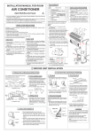
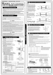
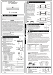
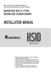
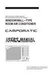
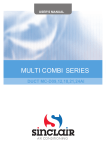
Keep Well This Manual.
Read Rules for Safe Operation and Instructions Carefully.
WINDOW TYPE
AIR CONDITIONER
USER'S MANUAL
CS0094(B)
CONTENTS
1.
FEATURES............................................................................................1
2.
ELECTRICAL SAFETY RULES.............................................................2
3. UNIT PARTS IDENTIFICATION.............................................................3
4.
POINTS FOR ATTENTION WHEN OPERATING..................................3
5. OPERATION PANEL..............................................................................4
6. OPERATION INSTRUCTION.................................................................5
7. CARE AND MAINTENANCE..................................................................9
8. TROUBLESHOOTING GUIDE..............................................................11
9. INSTALLATION.....................................................................................13
ELECTRICAL SAFETY RULES
CAUTION
F All wiring must comply with local and national electrical codes and
be installed by a qualified electrician. If you have any questions
regarding the following instructions, contact a qualified electrician.
F Never insert your fingers or any foreign objects into the air outlet.
Take special care to warn children of these dangers.
F To avoid the possibility of personal injury, be sure to disconnect
power to the unit before installing and/or servicing and/or cleaning.
F If the supply cord is damaged, it must be replaced by the manufacturer or its service agent or a similar qualified person in order to
avoid a hazard.
10. SPECIFICATIONS................................................................................16
1. This window-type air conditioner can adjust your room temperature automatically
and dehumidify the room which provide you with all of the "Home Comfort" requirements.
2. Adopts six advanced patent techniques and has the reliable performance.
3. Your air conditioner is a multi-functional room air-exchanging, air-processing
appliance with highly efficient in energy savings.
4. Providing two ways for your choice to deal with the condensed water, which
prolongs the unit life.
5. This unit is applied to all kinds of places including factories, mines, restaurants,
hospitals, hotels, home laboratories, computer rooms etc., Where adjustment and
control of room temperature and humidity are needed.
1
N
FEATURES
E
The air conditioner you purchased may be slightly different from the pictures in this
manual, the actual shape shall prevail. See the relative operations.
POWER
CORD
L
NOTE
1. The power cord is distinguished
according to the cord color just as follows
(see fig. 1):
2. For your safety and protection, this unit is
grounded through the power cord .(see
fig. 2). Please contact the manufacturer
or its service agent or a similar qualified
person if you want to replace it.
3. Be sure that the unit being correctly
grounded. The wall outlet (Air-break
switch)should be provided with reliable
earth wire.
4. The unit should be provided with an
individual branch circuit and the fuse size
should be same as that of the power cord
and wall outlet.(Air-break switch).
E-Ground wire, yellow/green
N-Neutral wire, blue
Fig. 1
L- Live wire, red/brown
Wall outlet
Air-break switch
Fig. 2
2
UNIT PARTS IDENTIFICATION
2
1
3
4
5
6
7
1. Front panel
2. Air filter
3. Frame
4. Cabinet
5. Air inlet grille (outdoor side)
6. Air outlet grille
7. Operation box
8. Power supply cord
2. Attaching the Air Filter
Before starting the air conditioner operation, make
sure that the air filter is well attached. If the unit has
not been used for a long time, it is recommended to
clean the air filter before your using the unit. For
continuous use, clean the air filter at least once every
two weeks.
3. Before turning on the unit, make sure that the air inlet
grille and air outlet grille are not obstructed by
anything.
4. This air conditioner is designed to be operated under conditions as follows:
8
O
O
Outdoor temp.: 18-43 C(T1Environment) 21-52 C(T3Environment)
Indoor temp.: 18-32 C(T1Environment) 18-32 C(T3Environment)
O
O
Cooling Operation
ACCESSORIES
Seal
1
Wooden screw
8
Drain Plug
(option)
Drain Pan
(option)
1
1
Screw(Fasten
the front panel)
2
Note: The relative humidity of home should be less
than 80%. If the unit is used in a condition with a
relative humidity over 80%, there will be condensed
water on the appearance of the unit.
O
O
Heating Operation Indoor temp.: -5 C-30 C
5 If the unit is operated beyond the conditions specified above, it may cause a failure
of the unit.
6. Relocation of the unit:
When changing the installation location of the air conditioner, consult the selling
agent from which you bought your unit.
OPERATION PANEL(Cooling only type)
POINTS FOR ATTENTION WHEN OPERATING
1. During the course of operating, if you have turned off
the unit or changed operation mode from COOLING
MODE to FAN MODE, be sure to keep that state for
at least three minutes before switching to COOLING
MODE again.
The operation panel would look like one of the following:
AUTO LOUVER
THERMOSTAT
0
COOLER
OFF
ON
LOW
FAN
WAIT THREE MINUTES
BEFORE RESTARTING
TEST RUN
3
SELECTOR
4
LOW
COOL
HIGH
FAN
HIGH
COOL
AUTO SWING
THERMOSTAT
SELECTOR
OFF
6
ON
OFF
3
9
HIGH
COOL
POWER
MED
COOL
Note
HIGH
FAN
LOW
FAN
When turning the SELECTOR knob from "LOW COOL" to "HIGH COOL", keep your speed slow as far
as possible. Do not change the operation mode between "LOW COOL" and "HIGH COOL" too often.
THERMOSTAT
THERMOSTAT
1
LOW
COOL
COOLER
COOLER
WAIT THREE MINUTES BEFORE RESTARTING
POWER indicator(some models without): This indicator light remains on when the unit
is on and goes off when the SELECTOR is on OFF position.
NOTE: The outline of the operation panel is based on typical model, the function is the
same with your air conditioner while some difference may exist in appearance.
OPERATION INSTRUCTION
OPERATION COVER
To set desired cooling temperature, simply rotate
the SELECTOR knob to the appropriate setting.
SELECTOR
HIGH FAN will circulate the air at a maximum
speed without cooling.
0
LOW FAN will circulate the air at a minimum
speed without cooling.
LOW
FAN
LOW
COOL
HIGH
FAN
HIGH
COOL
The operating method is as follows: turn along the arrow,
the temperature setting becomes lower, when you feel it is
too cool, rotate the knob to the"original" direction. When
you feel it is too heat, rotate the knob to the COOLER
direction.
Note
(some models without)
Note: Don't press or swing the opened
operation cover.
SELECTOR
TEST RUN
The thermostat automatically starts and stops the running
of the compressor in the air conditioner in order to control
and maintain a comfortable room temperature. When the
room temperature reaches the desired setting, cooling will
automatically stop. When the room temperature rises
above, cooling resumes. This results in efficient use of
power and economical cooling.
HIGH COOL provides cooling, automatically
with maximum air circulation.
LOW COOL provides cooling, automatically
with minimum air circulation.
0
will completely shut off the unit.
5
TEST RUN is used to test the compressor and make sure unit is working properly. When the
knob is rotated to this position, the unit is kept in cooling mode and automatic temperature control
is cut off. Do not use this position for regular operation.
During the cooling operation of the unit, when the thermostat knob is rotated clockwise, allow at
least three minutes before turning back the knob to the COOLER direction. Otherwise the fuse
may blow due to an overload of the unit.
AUTO LOUVER(/AUTO SWING)
Horizontal air flow adjustment (automatically)
OFF
ON
AUTO
LOUVER
(/AUTO SWING)
When the AUTO LOUVER(/AUTO SWING) switch is
turned to
ON
position, the vertical louvers
automatically oscillate right and left sweeping the cold
air alternately to obtain comfortable cooling. The
vertical louvers may be stopped at any position when
the AUTO LOUVER(/AUTO SWING) switch is
turned OFF .
6
& FUNCTION SELECTION(Cooling/Heating type)
Vertical air flow adjustment (manually)
To adjust vertical air flow direction, adjust any one of
the horizontal louver blades. When turning up or down
the horizontal louver blades, always keep horizontality
the top or bottom blades. This can effectively prevent
water drops condensed on the front panel of the unit.
SELECTOR
OFF
LOW
FAN
HIGH
FAN
LOW
COOL
LOW
HEAT
HIGH
COOL
HIGH
HEAT
(
9000Btu/h Model)
OPERATION PANEL(Cooling/Heating type)
OFF
The operation panel would look like one of the following:
AUTO LOUVER
(/AUTO SWING)
THERMOSTAT
SELECTOR
6
ON
LOW
HEAT
3
9
HIGH
FAN
1
SELECTOR
AUTO SWING
OFF
ON
OFF
9
LOW
FAN
HIGH
FAN
LOW
COOL
LOW
HEAT
12
COOLER
CAUTION
+ When the switch is set to HIGH FAN or LOW FAN , the air conditioner
only blows air, without cooling or heating.
+ Slowly turn the knob from LOW COOL (LOW HEAT) to HIGH COOL
(HIGH HEAT), do not turn it too often.
+ When room temperature drops below 21 C and the unit is cooling frost may form
on the evaporator. If this occurs, operate the air conditioner on the FAN(HIGH
FAN) setting to defrost.
& THERMOSTAT
POWER
1
9000Btu/h Model)
HIGH
COOL
HIGH
HEAT
12
6
HEATER
(
LOW
COOL
LOW
HEAT
WAIT THREE MINUTES BEFORE RESTARTING
3
HIGH
HEAT
COOLER
HEATER
THERMOSTAT
HIGH
COOL
OFF
LOW
FAN
OFF
LOW
COOL
FAN
The function selection knob controls fan speed or
cooling speed.
(1) When it is set to HIGH FAN , strong air flow
comes out.
(2) When it is set to LOW FAN , air flow becomes
weaker.
(3) When it is set to HIGH COOL , fast cooling is
achieved.
(4) When it is set to LOW COOL , tender cooling
can keep the temperature.
(5) When it is set to HIGH HEAT , fast heating is
achieved.
(6) When it is set to LOW HEAT , tender heating
can keep the temperature.
(7) When it is set to OFF , the air conditioner
does not run.
(8) When it is set to FAN , strong air flow comes
out.
HIGH
HEAT
HIGH
COOL
THERMOSTAT
WAIT THREE MINUTES BEFORE RESTARTING
6
POWER indicator(some models without): This indicator light remains on when the unit
is on and goes off when the SELECTOR is on OFF position.
NOTE: The outline of the operation panel is based on typical model, the function is the
same with your air conditioner while some difference may exist in appearance.
3
9
HEATER
Operate the thermostat knob as shown. The
temperature you are setting gets higher, from 6 to
1 , lower from 6 to 12 .
COOLER
1
7
The thermostat automatically starts and stops the
operation in order to keep the room temperature at a
proper level, and this results in efficient use of power
and economical cooling.
12
8
CAUTION
& During cooling operation, if you have turned the Thermostat knob in the direction
from (12) to (1), be sure to wait at least three minutes before returning the knob
back toward (12). Immediate returning of the knob may cause undue load to be
applied to the machine, resulting in a blown fuse.
& The knob does not go over the range between (1) and (12).
& For the type adopts PTC heater, when the SELECTOR is set to "HIGH HEAT" or
"LOW HEAT",the THERMOSTAT is out of function.
FRESH AIR VENTILATION
CLOSE
VENT
This is usually kept in the closed position and
use only when clearing smoke and/or odors
from the room. When the ventilation lever is
pushed to "CLOSE", the fresh air ventilation is
closed; when the ventilation lever is pushed
to "OPEN", the fresh air ventilation is opened.
Note: There is a little difference from the
operation method between the different
models. For some models, when the
ventilation lever is pushed forward, the fresh
air ventilation is closed; when it is pulled
outward, the fresh air ventilation is opened.
OPEN
VENTILATION LEVER
Do Not use gasoline, benzene, thinner
or any other chemicals, or any liquid
insecticide on the air conditioner, as
these substances may cause flaking
off of the paint, cracking or deformation
of plastic parts.
Never attempt to clean the unit by
pouring water directly over any of the
surface areas, as this will cause
deterioration of electrical components
and wiring insulation.
CLEANING THE AIR FILTER
If the air filter becomes clogged with dust, air flow is obstructed and reduces cooling
efficiency. The air filter should be cleaned every two weeks.
AIR FRESHER
Note
& The VENTILATION LEVER should
normally be kept in the CLOSED
position during cooling for maximum
cooling effect. The "OPEN" position is
used only for ventilation.
CARE AND MAINTENANCE
CAUTION
To avoid the possibility of personal injury, be sure to disconnect power to the unit
before servicing and/or cleaning.
9
1) The air fresher is fixed on the
backside of the air filter, clean it
together with the air filter.
2) Rinse the filter and fresher well using
clean water. Allow timer to dry it
completely.
4. Attaching the Air Filter
See INSTALLATION INSTRUCTION,
Step 5, on Page 15.
1. Removal of Air Filter
See INSTALLATION ,
Step 1, on Page 14.
2. Cleaning of Air Filter
1) Remove the dust clogged in the filter
by tapping it or vacuum clean it.
2) Wash the filter well with lukewarm
water or a neutral cleaning agent.
3. Cleaning of Air Fresher
10
Note
O
O
Never use hot water over 40 C(104 F) to clean the air filter and air fresher.
Never attempt to operate the unit without the air filter.
FRONT PANEL
& Dust may accumulate on the front panel, use soft wet cloth with a neutral cleaning
agent to wipe it.
& Never use water over 50 C, alcohol, gasoline, acid, solvent or brush to clean the
O
front panel as this will damage the surface of the part.
In-Season Care
End-of-Season Care
3
1. Operating the fan alone for half a day
to dry out the inside of the unit.
2. Turn off power and disconnect the
power supply.
See POINTS FOR ATTENTION
WHEN OPERATING on page 3.
TROUBLESHOOTING GUIDE
Ventilation lever is set at "OPEN".
No Air Flow
Poor Cooling Though Air Flows Out Normally
11
12
INSTALLATION
& Select The Best Location
F Install the unit at a place having sufficient strength to support the unit securely.
F For maximum efficiency, install the air conditioner on a side of a house or building
which favors more shade than direct sunlight.
F Provide sufficient clearance or space around the air inlet and air outlet so that air
flow will not be obstructed, following figures give detailed requirements.
F Only trained and qualified service personnel should install, repair or service air
conditioning equipment. Users should not install the air conditioner by themselves.
The Treatment of Condensed Water
To meet different requirement of different type of
air conditioner, there are two kinds of methods for
your choice to treat the condensed water.
For Cooling Only Models:
1. If no need to drain off water, seal the drain hole
at the bottom of the cabinet with a rubber
stopper. This will increase efficiency, but the
noise might be louder.
2. If need to drain off water, install the drain plug
and connect with drain hose. The drain hose is
available in local market (see Fig.A).
For Cooling and Heating Models:
1. Install the drain plug and connect with drain hose.
The drain hose is available in local market
(see Fig. A)
Another way to drain off water:
1. Install the drain pan over the area of the cabinet
where you removed the plug, and secure with 2
screws provided.
2. Connect the drain hose to the outlet located at
the bottom of the drain pan. You can purchase the
drain hose or tubing locally to satisfy your particular
needs (Drain hose is not supplied)(see Fig.B) .
Fig.A
CABINET
DRAIN
PAN
DRAIN HOSE
OUTLET
RUBBER
PLUG
SCREW
Fig.B
Installation Step
Step 1. Remove the front panel and the air filter.
Fig.3
1. Hold the slot under the front panel, then uplift it onwards, and remove the front panel
later. (see Fig.1)
2. Pinch the handle under the air filter and make the air filter arched, remove it from
the slot from underside to upside. (see Fig.2)
13
14
SPECIFICATIONS
MODEL
(Btu/h)
Step 2. Remove the frame.
5000~6000
1. Remove the two fixed screws from the frame. (see Fig.3)
2. Grasp the left corner in the frame's underside, the loosen the frame. (see Fig.4)
7000~9000
Step 3. Installation
1. Remove the screws fix the chassis-fixing board and cabinet. some Models have
two more screws on the back of the cabinet. (see Fig.5)
2. Grasp the handle on the chassis and carefully slide the air conditioner out of the
cabinet. (see Fig.6)
3. When need to drain off water, in tall the drain pluq on the Chassis board. Then fix
the cabinet on the supporter (provide for yourself or contact the dealer)(see Fig.7).
4. Push the unit chassis into the cabinet. (see Fig.8)
5. Fix the chassis and cabinet.. (see Fig.5)
BODY DIMENSION(mm)
(W X H X D)
445X320X400
450X350X540
520X340X560
3*1.0
15000~16000
660X435X640
3*1.5
18000~28000
660X430X770
3*2.5
SUPPORTER
SCREWS
Fig.9
Step 4. Install the frame
1. Install the frame. (see Fig.9)
2. Fix the screws on the frame. (see Fig.3)
Step 5. Install the front panel and the air filter.
1. Install the air filter into the frame's slot from upside to
underside. (see Fig.2)
2. Hang the front panel on the frame's buckle, then press
the front panel into the frame's slot until hear a click.
(see Fig.10)
15
3*1.0
560X400X650
CABINET
Fig.8
3*1.0
10000~12000
WALL
Fig.7
WIRING SIZE
(mm2 )
Fig.10
16