1
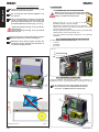
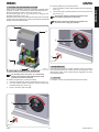
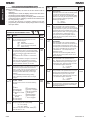
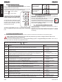
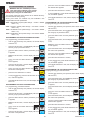
To lock the gearmotor, proceed as follows:
1. Turn the release system anti-clockwise until it stops (Fig.
Once operator installation has been completed, carefully check
25 ref. b).
operation of all the connected accessories and safety devices.
2.
Turn the key anti-clockwise and then remove it from the lock
Refit the transparent guard covering the control unit.
(Fig. 25 ref. a).
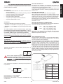
Fit the housing (Fig. 23 ref. b) and secure it using the four
provided screws (Fig. 23 ref. a).
Turning the release system knob clockwise will
Give the customer the “User’s Manual” and show how to correctly
prevent any movement of the motor.
operate and use the gearmotor, pointing out the areas of potential
danger of the automated system.
Operator releasing and locking operations can
be carried out in any gate position.
a
a
b
b
a
a
Fig. 25
a
9 MAINTENANCE
Fig. 23
We recommend checking system operation every six months,
with special attention to the safety devices (including the motor
thrust power, which must comply with the regulations in force)
and release devices.
8 RELEASING/LOCKING THE OPERATOR
To manually move the gate, we recommend
cutting off electrical power. Rotating the knob
prevents any motor movement.
10 REPAIRS
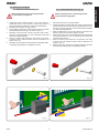
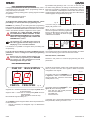
To release the gearmotor, proceed as follows:
1. Insert the provided key and turn clockwise (Fig. 24 ref. a).
2. Turn the release system clockwise until it reaches the
mechanical stop (Fig. 24 ref. b).
3. Open or close the gate manually.
For repairs, contact an authorised FAAC Service Centre.
b
a
Fig. 24
C850
13
532015 Rev. A
ENGLISH
7 TESTING THE AUTOMATED SYSTEM