1
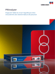
FRAnalyzer
Reliable Core and Winding Diagnosis for Power Transformers
Sweep Frequency Response Analysis (SFRA)
The OMICRON FRAnalyzer detects mechanical and electrical changes of the core and winding assembly of power transformers. By
finding winding or core defects after faults, mechanical shocks (e.g. earthquakes) or transportation, it offers a valuable opportunity to
improve the reliability of transformers, to reduce maintenance costs and, most of all, to avoid expensive unexpected outages.
What Is FRA?
Frequency Response Analysis (FRA) is a powerful and
sensitive method to evaluate the mechanical integrity of
core, windings and clamping structures within power
transformers by measuring their electrical transfer
functions over a wide frequency range. OMICRON uses
the SFRA principle (sweep frequency response analysis)
– a worldwide proven method for measurements in
frequency domain. The SFRA is a comparative method,
i.e. an evaluation of the transformer condition is done
by comparing an actual set of SFRA results to reference
results. Three methods are commonly used to assess the
measured traces:
SWEEP FREQUENCY RESP
Sine generator
Transformer
5.0
3.0
1.0
-1.0
0.2
0.4
0.6
0.8
1
1.2
-3.0
5.0
>> time-based
variable frequency
(current SFRA results will be compared to previous
results of the same unit)
>> type-based
(SFRA of one transformer will be compared to a typeequal one)
>> phase comparison
(SFRA results of one phase will be compared to the
results of the other phases of the same transformer)
complex
RLCM-network
Amplitude
When to Use SFRA?
Typical applications of SFRA measurements are:
>> Transformer check after short circuit testing
The FRAnalyzer injects a sinusoidal excitation
voltage with a continuously increasing frequency
into one end of the transformer winding and
measures the signal returning from the other
end. The comparison of input and output
signals generates a unique frequency response
>> Integrity verification of transformers after transport
>> Condition assessment after the occurrence of high
transient fault currents
>> Routine diagnostic measurement
>> Diagnosis after transformer alarm or protection
tripping
>> Testing after significant changes of monitored values
(e.g. combustible gases)
>> Further inspection after the observation of unusual
routine test results
>> Scientific investigations
2
Why OMICRON FRAnalyzer?
>> Use of the SFRA principle – the industry standard for
measurements in frequency domain
>> Extremely small size and weight using leading edge
>>
>>
PONSE ANALYSIS (SFRA)
>>
>>
5.0
>>
3.0
1.0
-1.0
0.2
0.4
0.6
0.8
1
>>
1.2
technology, for easy handling
Highest convenience resulting from battery operation
Best repeatability due to an innovative connection
technique based on the latest scientific findings
Easy-to-use creative software with implemented
standard-based assessment solution
World-class OMICRON customer support and valuable
trace assessment help by technology experts
Free access to the OMICRON SFRA-User Forum
Effective, practice-oriented trainings offered at
OMICRON training centers or on-site at your location
-3.0
5.0
Phase
which can be compared to reference data.
Deviations indicate geometrical and/or electrical
changes within the transformer. No additional
data processing is required due to a direct
measurement in the frequency domain.
Your Benefits :
>> SFRA is a non-intrusive test method, easy and fast
to perform
>> SFRA also covers low frequencies and thus can
detect core faults, shorted or open turns
>> Direct measurement in frequency domain (as
opposed to the time domain measurement
method) – thus no further mathematical
handling of data is necessary
>> Increasing possibilities for SFRA knowledge
transfer and improvement of method through
growing number of users and scientific research
efforts
3
Power Transformer Core & Winding Diagnosis
What Problems Can Be Detected?
How Does It Work?
>> The FRAnalyzer can detect problems such as: winding
Each electrical network has got its unique frequency response.
Therefore it is usually called a fingerprint. Geometrical changes
within and between the elements of the network cause
deviations of its frequency response.
>>
>>
>>
>>
>>
>>
>>
deformation – axial & radial, like hoop buckling, tilting,
spiraling
displacements between high and low voltage windings
partial winding collapse
shorted or open turns
faulty grounding of core or screens
core movement
broken clamping structures
problematic internal connections
Deformed core
Collapsed tap winding
Damaged main winding
Displaced internal connections
Differences between an SFRA fingerprint and the result of an
actual measurement are an indication of positional or electrical
variations of the internal components. Different failures are
directly related to different sections of the frequency range and
can usually be discerned from each other.
4
windings
C
core
C
R
L
LR
C
C
C
C
R
L
C
C
tank
wall
LR
C
C
C
C
The core-and-winding-assembly of power transformers
can be seen as a complex electrical network of
capacitances, inductances and resistors.
Your Benefits:
>> High reliability of test results due to the applied
measurement method and high repeatability
of test results due to sophisticated connection
technique
>> SFRA can detect winding and core problems
which remain hidden using any other diagnostic
method
>> Valuable and cost-effective tool for deciding
whether a transformer can be powered up again
after protection tripping or not
>> Informative failure analysis helps avoid expensive
defueling of transformer's active part
5
Unique Connection Technique
The OMICRON FRAnalyzer uses an innovative connection technique to enable exceptional repeatability of the test results.
Exceptional Repeatability with Advanced
Connection Technique
Since SFRA is a comparative method, it is of vital
importance that measurements on the same object under
the same conditions produce identical results regardless
of the external noise level.
Only a very high degree of repeatability can ensure that
even small deviations of compared SFRA-traces are related
to changes within the observed transformer and not to
inaccuracies within the measurement setup.
According to the standard of knowledge, the connections
between the measuring device and the transformer
terminals, as well as the grounding technique, have a key
influence on reproducibility.
Unique Connection Technique
In close cooperation with leading Universities in the field
of FRA testing on power transformers, OMICRON has
developed a sophisticated connection solution to achieve
highest possible repeatability of the results.
Specially designed screw-type-connection clamps
provide reliable electrical contact to the transformer. The
FRAnalyzer uses double shield coax cables (RG223U) to
ensure the highest available signal-to-noise-ratio (SNR).
6
To enable the grounding of the coaxial cable shields at the
transformer housing, which is the reference potential, an
additional connection from the terminal adapter to the
transformer tank is required.
A poor grounding technique can lead to unreproducible
and therefore unusable SFRA results. In order to achieve
the best possible SFRA measurements, the grounding
connections should be of lowest inductance and provide
a large surface area.
Therefore the use of braids, which are less sensitive to
interferences and make the measurement independent
from the cable positioning is strongly recommended.
The Double-Braid Concept
OMICRON provides a double-braid solution which forms a
shield around the bushing arranged in a defined position.
In order to achieve a high degree of repeatability, the
extension leads should run tightly along the body of the
bushings. This is ensured by screw clamps which connect
the braids always with ideal length to the base of the
bushing.
Due to their high flexibility the tester can lay the braids
tightly to the bushing. This clamp-and-braid arrangement
complies with the strict demands of engineers around
the globe requiring a "ground extension as short as
possible and with the smallest achievable loop" – only the
FRAnalyzer provides this in such an exceptional manner.
Your Benefits:
>> True-value results due to accurate reproducibility
>> High-end clamps for exceptional repeatability
>> Minimal noise interference due to the use of
two broad ground braids
>> Time saving because of cutting functionality of
screw-type clamps
7
Fast, Easy and Efficient Software
The FRAnalyzer software is specially designed to fit the needs of the on-site testing personnel as well as the requirements
of the engineers analyzing the data. The tests are easy to establish and fast to perform. The software suggests useful test
sequences according to transformer type and vector group. An implemented assessment algorithm gives the user a powerful
tool for a fast analysis of the results. The auto-report functionality generates a complete report within seconds.
Getting Started
Usually the test sequence starts with the establishment of
the transformer to be tested. The nameplate data will be
stored with all measured data. The terminal markings can
be chosen from different templates such as IEC or ANSI.
If there is older data of the same transformer (fingerprint)
available in the database, this test can be used as a
template.
Based on transformer type and vector group, a test
sequence is suggested. Other sequences can also
be added and changed freely and individually. The
new Connection Scheme (shown in the upper right
screenshot) is an ideal, easy-to-use graphical support
for unexperienced users for a proper assignment of the
connections. The preview pane gives a quick overview of
curves.
Sweep Settings
Any test with the FRAnalyzer is performed with a sweep
settings profile. These profiles are fully customizable and
can be set for any test individually. In contrast to other
instruments, the spacing of the FRAnalyzer measurement
points (sweep mode) can be logarithmic or linear, there
can also be generated as many frequency sub-ranges
as needed. In addition to the number of points, the
receiver bandwidth can be adjusted to achieve an optimal
signal-to-noise ratio (SNR).
Your
Comp
an
Heade y
r
With one look, the user can get an overview of the
magnitude (gain) and phase angle of the transformer's
transfer function. It is possible to group the shown traces,
e.g. just HV measurements, or just the results of the
tertiary winding. Cursors are available as well as an easy
to use zoom functionality. A copy-to-clipboard function
allows a fast insertion of full or zoomed trace pictures
into office documents, etc. Despite the predefined sweep
mode, the traces can be displayed in linear or logarithmic
scaling to observe every part of the trace in a useful way.
8
The Reference Principle
After the measurement a reference test can be defined.
This can be a fingerprint of the same transformer or
measured data of various sister transformers. Of course
it is also possible to compare the traces measured on
different phases of a transformer without setting a
reference test.
Implemented Assessment Tool
The FRAnalyzer provides the user a mathematical solution
for a comparison of the traces based on the standard DL
911/2004.
Assessment tool confirms healthy winding status
Scientific investigations and experience have proven
this method to be reliable and sensitive. Therefore the
implemented algorithm provides a powerful tool for a fast
assessment of the test data.
Data Storage, Export/Import
All measured data is stored within a supplied database.
This ensures a time-effective data handling and avoids
the problems typically arising with file storage systems
for a large number of tests. These stored data can easily
be arranged and sorted by several parameters. An easyto-handle export function enables the user to store the
data additionally in different formats such as CIGRE
Exchange Format (.xfra) or .csv (which can be imported
into MS Excel™). The FRAnalyzer software also allows
the import of other manufacturers data in their specific
formats such as Doble, FRAMIT, FRAX, etc.
Failure clearly identified by the assessment tool
Your Benefits:
>> Fast, easy, efficient handling through the user
interface
>> High flexibility due to freely selectable sweepsettings
>> Cost saving due to included database solution
>> Included assessment tool saves money otherwise
spent on expert analyses
>> Easy localization to global market via different
language packages
>> Effective work due to the fast auto-reporting
>> Helpful connection schemes support the
unexperienced user to make the right
connections
>> Easy to use comparison of multiple tests
>> Increased import and export functionality
The Auto-Report Function
The FRAnalyzer software automatically generates a test
report within seconds. It can be printed out or stored
in .pdf format or MS Excel™. It contains all information
about the transformer, the test, all traces and assessment
results.
9
The 'one box' Solution
The complete FRAnalyzer package comes in a firm arrangement – every component has its place. The complete package
is designed for field use and has successfully passed vibration-, shock- and climatic resistance tests by an independent
and accredited test laboratory.
Technical Data
General
Enviromental
Frequency range
10 Hz bis 20 MHz (selctable)
Meas. point spacing
logarithmic, linear, or both
Calibration interval
every 3 years
Operating ambient
temperature
Operating relative
humidity
Source Output
-10...+55 ºC / +14...+131 ºF
20... 95 %, non-condensing
Mechanical data / supply voltage
FRA method
Sweep frequency
Weight
< 2 kg without measuring cables
Output impedance
50 Ω
26 x 5 x 26.5 cm / 10.25 x 2 x 10.5 in
Connector
BNC (double shielded)
Amplitude
2,83 V p-p = 1 Vrms at 50 Ω load
Dimensions
(W x H x D)
DC power supply
Number of meas. points max. 3,201 (user-selectable)
AC power supply
AC 100 V to 240 V / 50 to 60 Hz
Inputs (Reference – CH 1, Measurement – CH 2)
PC requirements (minimum)
DC 10 V to 24 V / 10 W
Interface
USB 1.1
Connector
low 50 Ω, or high impedance 1 MΩ
(selectable)
BNC (double shielded)
PC operating system
Dynamic range
> 120 dB
Processor
Windows™ 2000, Windows XP™ or
Windows Vista™ 32bit
Pentium™ 1 GHz
Accuracy
< 0,1 dB (down to -50 dB) and
±1 dB (between -50 dB und -80 dB)
Memory
256 MB RAM
Drive
CD-ROM
Impedance
PC Software 'OMICRON FRAnalyzer' for
10
>
Operation of the FRAnalyzer
>
Measurements with test templates
>
Advanced visualization and analysis of test results
>
Assessment of the measuring results
>
Database handling
>
Reporting
Ordering Information
VE000660
FRAnalyzer complete set
The set consists of the following accessories (can also be ordered separately; one piece per order no):
Order No.
Qty. Description
VEHK0660
1
Coaxial-Cable Red with Cable Drum (18 m / 59 ft)
VEHK0661
1
Coaxial-Cable Blue with Cable Drum (18 m / 59 ft)
VEHK0662
1
Coaxial-Cable Yellow with Cable Drum (18 m / 59 ft)
VEHZ0661
4
Aluminum Braid Rolls (5 m / 16 ft)
VEHK0615
1
Grounding Cable 6 mm² gn/ye (6 m / 20 ft)
VEHZ0662
4
Screw-Clamps for Aluminum Braid
VEHZ0664
2
Bushing-Clamps
VEHZ0667
1
BNC Adapter Set
VESD0662
1
User Manual
VEHZ0659
1
Power Supply and Battery Charger
VEHZ0657
1
Crank Handle
-
1
FRAnalyzer Software
Additional Accessory for FRAnalyzer:
VEHZ0673
Clamps Set for Short Bushings
(consisting of 2 short aluminum braids (1.5 m / 5 ft), 2 clamps and 1 carry bag)
VESM0661
FRAnalyzer Software Upgrade to 2.0
(for users of older software versions than 2.0)
11
OMICRON is an international company serving the electrical power
industry with innovative testing and diagnostic solutions. The
application of OMICRON products provides users with the highest
level of confidence in the condition assessment of primary and
secondary equipment on their systems. Services offered in the
area of consulting, commissioning, testing, diagnosis, and training
make the product range complete.
Customers in more than 130 countries rely on the company’s
ability to supply leading edge technology of excellent quality.
Broad application knowledge and extraordinary customer support
provided by offices in North America, Europe, South and East Asia,
Australia, and the Middle East, together with a worldwide network
of distributors and representatives, make the company a market
leader in its sector.
For a detailed list of literature currently available please visit the Literature & Videos section of our website.
Americas
OMICRON electronics Corp. USA
12 Greenway Plaza, Suite 1510
Houston, TX 77046, USA
Phone: +1 713 830-4660
+1 800-OMICRON
Fax:
+1 713 830-4661
[email protected]
© OMICRON L179, Mai 2010
Subject to change without notice
Asia-Pacific
OMICRON electronics Asia Limited
Suite 2006, 20/F, Tower 2
The Gateway, Harbour City
Kowloon, Hong Kong S.A.R.
Phone: +852 2634 0377
Fax:
+852 2634 0390
[email protected]
Europe, Middle East, Africa
OMICRON electronics GmbH
Oberes Ried 1
6833 Klaus, Austria
Phone: +43 5523 507-0
Fax:
+43 5523 507-999
[email protected]
www.omicron.at • www.omicronusa.com