1
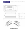
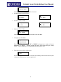
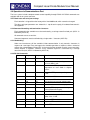
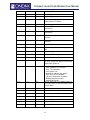
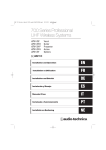
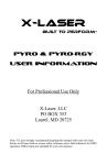
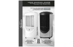
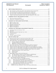
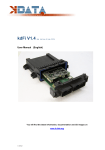
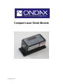
Compact Laser Diode Module
115-80040-001 Rev 2
Compact Laser Diode Module User Manual
Contents
1 Safety Precautions ..................................................................................................................................... 3
2 Application and Features ........................................................................................................................... 4
3 Specifications ............................................................................................................................................. 4
4 Operating Procedures ................................................................................................................................ 7
5 Maintenance............................................................................................................................................. 13
6 Service ..................................................................................................................................................... 13
2
Compact Laser Diode Module User Manual
1 Safety Precautions
This instruction manual explains how to use the Compact Laser Diode Module.
Before use, please read this manual thoroughly. After reading, keep it together with the product for
reference when necessary. Please retain packaging material in the event the unit is stored or shipped in
the future.
1.1 Explanation of Warning Symbols
The meaning of the symbols used in this manual and attached to the product follows.
Warning messages are intended to prevent accidents to operating personnel such as burns and electrical
shocks.
Caution messages are intended to prevent damage to the module.
Precaution for handling electrostatic sensitive devices.
Laser emission port, DO NOT STARE INTO BEAM OR VIEW DIRECTLY WITH OPTICAL
INSTRUMENTS.
Warranty void if removed
Warranty void if removed. Do not open the module.
Warning
To prevent permanent damage, observe these precautions:
1. Protect against electrostatic discharge.
2. Avoid external damage to the enclosure.
3. Use supplied power supply or power supply
meeting specifications.
4. Do not drop the module or operate it at extreme
temperatures or humidity.
3
Compact Laser Diode Module User Manual
2 Application and Features
2.1 Applications
This device is a compact laser diode module with integrated laser diode current driver and temperature
control for high precision equipment and instrumentation. It plays a pivotal role in testing or
manufacturing, and can be used in various applications such as Flow Cytometry, Confocal Microscopy,
Protein Crystallography, DNA Sequencing, Semiconductor Defect Detection, Thin Film Analysis, High
Density Data Storage, and Raman Spectroscopy.
2.2 Standard Features
•
Plug & Play Operation
•
Remote Computer Control Capability
•
ESD Protection
•
Built-in User Interface Panel
•
Constant Current Driver
•
Temperature Stabilized
•
Adjustable Output Power
•
LCD Display with Buttons for Adjusting Settings
•
Adjustable Temperature Setpoint
•
Compact Size
3 Specifications
OPTICAL
Power Stability (over 1 hr)
< 1%
Laser Noise ( 10 to 1Mhz) RMS
< 1%
Laser Class
Class 1, 2, 3a and 3b
Laser Operation
CW
Spatial Mode
TEM00
Beam Divergence (full)
< 1 mrad
Beam Size at Aperture (FWHM)
< 1 mm
Beam Pointing Stability
< ± 10 µrad
Polarization (typical)
> 100:1, vertical or horizontal
Warm-up Time
< 5 min
ELECTRICAL
Operating Voltage
3.3 V DC
Operating Current
1.5 A max
MECHANICAL
Laser Dimension
40 mm x 42.5 mm x 100 mm
Weight
< 1 lb
Operating Temperature
+10ºC to +40°C
Storage Temperature
-40ºC to +80°C
4
Compact Laser Diode Module User Manual
Figure 2: Mechanical Dimensions
5
Compact Laser Diode Module User Manual
7
6
1
Pins
1
2
3
4
5
6
7
8
9
Definition
VCC
TXD
RXD
GND
TTL CON
GND
2
8
3
9
4
5
Description
Positive Power Pin +3.3V.
Send data to computer (RS232)
Receive data from computer (RS232)
Not used
GND for power and RS232 communication
Outside TTL modulation
Not used
Not used
GND for power and RS232 communication
Note: Pinout is compatible with standard RS232 cable for interfacing with computer port or USB-RS232
adapter. Unit mates with a female DB9 connector.
2.1 x 5.5mm Center Positive Standard Jack for supplying operating voltage and current
GND
VCC
Figure 2 – Electrical Connections
Power LED: LED on indicates power on
Laser LED: LED on indicates laser on
Status LED:
Meaning
Rapid flashing (30 ms on / 30 ms off)
Waiting for temperature to be stable after power
on
Fast flashing (100 ms on / 100 ms off)
Waiting for 30 seconds
Flash 1 time (200 ms on / 200 ms off) every 2 s (LED
off)
Running normally
Flash 1 time (200 ms off / 200 ms on) every 2 s (LED
on)
Over current shut down
Flash 2 times (20 0ms off / 200 ms on) every 2 s
(LED on)
Over temperature shut down
Solid
Waiting for settings change using push buttons
6
Compact Laser Diode Module User Manual
4 Operating Procedures
4.1 Standard CW Operation
Laser module can be operated with or without RS232 communication port. Settings can be accessed
via push buttons on the laser module as well as RS232 port.
User Startup Procedure:
•
Properly mount laser module on a heat sink
•
If necessary, connect DB9 interface cable
•
Connect power supply
Laser Module Startup Process:
Laser module controller will follow/indicate the following process after power on:
•
System will ask to enter password. Default password is 0000.
•
The power LED on indicates the controller has received power. Default operating conditions
are stored in onboard flash.
•
The TEC activates to stabilize temperature to temperature setpoint. Setpoint can be changed
via RS232 or push button interface. It will take a few seconds depending on the setting point
and environmental conditions. During this period the status LED will flash rapidly.
•
Wait 30 seconds before the laser diode emits the power and the status LED will keep flashing
fast. Laser controller only operates in constant current mode. Status LED flashes according
to table above.
Warning: Laser module will emit light 30 seconds after providing power.
4.3 Push Buttons and LCD Display
The laser controller has 4 push buttons (“MENU”, “UP”, “DOWN”, “ENTER”) and a 2x16 LCD
alphanumeric information display. . The pushbuttons are used to change various controller settings
and laser operation parameters. “MENU” is used to enter or to exit the menu level. “UP” and
“DOWN” are used for navigation and change values. “ENTER” chooses menu levels and confirms
settings.
•
Version display. The LCD shows the software version information for 5 seconds when the unit power
is on.
Ondax
SN:B099999 V3.27
•
Entering password. If password is entered incorrectly for three times, the unit would be locked until
power is cycled (unplug and reconnect power cord). Default password is 0000.
Ondax
Password: 0000
7
Compact Laser Diode Module User Manual
•
Wait for temperature stability after the unit power is on. Temperature setpoint is based on stored
setpoint. Display shows actual temperature and TEC current:
Wait TEC Setup
22.00ºC 100.00mA
•
Wait 30 seconds for temperature stability. Display shows time countdown:
Wait (sec):30.0
22.00ºC 100.00mA
•
Main parameter display during normal operation.
Display different operating parameter:
•
Normal run mode (constant current).
Laser(I): 100.0mA
22.00ºC 200.0mA
100.00mA: laser operating current
22.00ºC: temperature, 200.00mA: TEC current
•
The parameter display can be cycled through the following modes by pressing “ENTER”
Temp: 22.00ºC
TEC Cur:200.00mA
.
Current:100.00mA
Temp: 22.00ºC
•
Error Messages. Laser will display appropriate message if it reaches conditions that are unsafe.
•
Laser over current. Press “MENU”, and then press “ENTER” to reset the unit.
Over Current
Shutdown Restart
•
Over temperature shut down. Press “MENU”, and then press “ENTER” to reset the unit.
Over temperature
Shutdown Restart
•
Switching off
8
Compact Laser Diode Module User Manual
•
Both the laser and TEC drivers can be switched off by pressing “DOWN” while in normal
mode.
TEC,LD Operation
Enter OFF_
After confirmation, the controller stops both drivers and it changes the screen to the
following one.
TEC & Laser OFF
Any key restart
The system will restart by pressing any pushbutton.
•
Settings Display
The setting menu block is selected by pressing “MENU” in a normal running mode. Within
the menu block, pressing “UP” or “DOWN” navigates between menu items. Press “ENTER”
to select the item. Pressing “MENU” will exit the setting menu without saving the changes to
flash. All the settings will go back to the previous setting after the unit is reset or re-powered.
•
Set TEC temperature
Set TEC Temp
10-50ºC: 22.00
22.00: The previous set point
Press “ENTER” to change the temperature set point. Otherwise press “UP” or “DOWN”
to change the setting menu
After pressing “ENTER” the unit will enter the parameter setting mode and the cursor will
change from “S” to “2” which is the first digit of the parameter. Then press “UP” or
“DOWN” to change the digit from “0” to “9” or “.”. After finished setting this digit, press
“ENTER” to move to next digit. When you finish setting the last digit and press “ENTER”
the parameter will affect right away then the cursor will revert to “S” at the same time. All
the following parameter settings are the same.
Set TEC Temp
10-50ºC: 22.00
•
TEC Operation
TEC Operation
TEC Operation
State: ON
State: OFF
Press “ENTER” to select TEC operation and the cursor will go down to the “O”. Then
pressing the “UP” or “DOWN” will set TEC on or off. The TEC will not turn on or off until
pressing “ENTER” to confirm the operation. Pressing “MENU” will cancel the change.
All the following setups for selecting ON/OFF or Disable/Enable are the same as the TEC
operation.
•
Set ACC Current
9
Compact Laser Diode Module User Manual
Set ACC Current
<=100.0mA:100.00
The maximum ACC current is the ACC full current.
•
•
•
Disable/Enable Laser ACC Driver
ACC Operation
ACC Operation
State: Disable
State: Enable
On/Off Laser ACC Driver
ACC Operation
ACC Operation
State: ON
State: OFF
Set Laser Current Limit
Max Current Limit
(mA): 400.00
If the laser current is over this value the laser will be shut down.
•
Change Laser Run Mode
Change Run Mode
Run Default Mode
Press “ENTER”, and then press “UP” or “DOWN” to change the run mode to “Internal
Modulation” or “Default”. Settings change only takes effect when exiting the setting
menu. “Internal Modulation” is unsupported and should not be used.
•
Save to flash and exit the setting menu
Save to Flash
and Exit
All the setting parameters will be saved to flash memory. So the laser will keep this
setting even when the unit is reset or repowered.
10
Compact Laser Diode Module User Manual
4.4 Operation via Communications Port
The laser system includes complete remote control capability through RS232. All RS232 commands are
available after laser system auto start.
4.4.1 Baud rates and serial port settings
Each controller is shipped from the factory with a fixed 9600 baud, which cannot be changed.
The other serial port parameters are: 8 data bits, 1 stop bit and no parity. A hardware flow control is
not supported.
4.4.2 Command formatting and termination characters
Each command to the controller must be terminated by a carriage return/line feed pair (ASCII 13
followed by ASCII 10).
All commands are case-sensitive.
Command arguments must be delimited by a single colon ‘:’ character (ASCII 58).
4.4.3 Handshaking
Under no circumstances will the controller initiate communication. It only transmits characters in
response to a message. Every message to the controller generates a response, either a numerical
value or the acknowledgment string “OK”. In the event that the controller receives a message that it
cannot interpret, it responds: “ERROR”. Every controller response is terminated by a carriage
return/line feed pair (ASCII 13 followed by ASCII 10).
4.4.4 RS-232 Commands
Commands
Argument
Response
Function
rlp?
No
**.**
Return the laser output power in mW
rli?
No
**.**
Return the present operating current of
the laser diode in mA
rtt?
No
**.**
Return the TEC present measured
temperature of laser diode in degrees
Celsius
rti?
No
**.**
Return the TEC present operating current
in mA
len
No
OK
Enable laser APC driver
ldis
No
OK
Disable laser APC driver
lon
No
OK
Turn on the laser emission output power
loff
No
OK
Turn off the laser emission output power
stt:
**.**
OK
Set the TEC temperature in degrees
Celsius(Default:22 Degree)
slc:
**.**
OK
Set ACC driver current in mA
clfp:
**.**
OK
Calibrate the laser power/Set the laser full
power value in mW
stm
No
OK
Start inner TTL modulation
ctm
No
OK
Stop inner TTL modulation
tecon
No
OK
Enable TEC control
11
Compact Laser Diode Module User Manual
tecoff
No
OK
Shut down TEC control
sps
No
OK
Start APC power scan
cps
No
OK
Stop APC power scan
slp:
**.**
OK
Set the laser output power from 0.0 to full
power(Default: Full power)
rsv?
No
******
Return the laser system firmware version
stont:
**.**
OK
Set inner TTL modulation on time, no less
than 0.01ms
stofft:
**.**
OK
Set inner TTL modulation off time, no less
than 0.01ms
stsont:
**.**
OK
Set power scan on time in ms, no less
than 0.01
stsofft:
**.**
OK
Set power scan off time in ms, no less
than 0.01
ssps:
***
OK
Set APC power scan step
rslp?
No
**.**
Return the present laser setting power in
mW
rclp?
No
**.**
Return the present laser full power
rstt?
No
**.**
Return the TEC set up temperature
rstli?
No
**.**
Return the ACC set up current in mA
ssc
No
OK
Save the setting to the flash memory so
the laser system can operate in the same
setting after repower it
rlrs?
No
*
smlc:
**.**
OK
Read laser controller run status
1, Laser controller runs normally
2, Inner TTL modulation
3, Laser power scan
4, Waiting for calibrate laser power
5, Over laser current shutdown
6, TEC over temperature shutdown
7, Waiting temperature stable
8, Waiting 30 seconds
Set the maximum laser diode current in
mA, if the current is over the limit the laser
will shut down.
rlcm?
No
**.**
Read the maximum laser current in mA
reset
No
OK
Reset the laser controller
rsn?
No
*******
Return the laser controller serial number
lcen
No
OK
Enable ACC laser driver
lcdis
No
OK
Disable ACC laser driver
lcon
No
OK
Turn on ACC laser driver
lcoff
No
OK
Turn off ACC laser driver
12
Compact Laser Diode Module User Manual
5 Maintenance
5.1 Maintenance and Inspection
Routine maintenance is not required. If the unit appears to be operating incorrectly or with low output
power, check the following:
•
Inspect the enclosure for scratches, dings, dents, or other signs of damage due to handling.
•
Verify that the module enclosure has not been opened and the factory seal is intact.
•
Verify power source connections to the laser module.
•
Ensure that the operating environment is within specifications.
6 Service
6.1 Repair
If the module fails during use, check the items in section 5.1 before requesting an RMA.
Defective modules that are beyond the warranty period will be repaired at cost, if possible. An RMA must
be requested before sending it to Ondax. When shipping, please use a box at least five times as large as
the module with enough packaging material to prevent any movement of the module within the box.
6.2 For Information or Enquiries
If you need information regarding purchase or repair, or for any other Sales related questions, please
contact the distributor or selling agent from whom the module was purchased.
6.3 Ondax Limited Warranty
TM
Ondax warrants that all SureLock integrated laser modules (RO, FCLM, LM) will be free from defects
in material and workmanship for 12 months from the date of shipment. This limited warranty covers only
those defects that arise as a result of normal use of the product, and does not cover any other problems,
including those that arise as a result of: (i) improper handling, maintenance or modification, (ii) operation
outside the product’s specifications; or (iii) unauthorized modification or misuse.
If Ondax receives, during the applicable warranty period, notice of a defect in any product which is
covered by this warranty, Ondax shall either repair or replace the product, at Ondax's option. Ondax shall
have no obligation to repair, replace or refund until the customer returns the defective product to Ondax.
Any replacement product may be either new or like-new, provided that it has functionality at least equal to
that of the product being replaced. Ondax products may contain remanufactured parts, components, or
materials equivalent to new in performance.
Limitations of Liability
1. TO THE EXTENT ALLOWED BY LOCAL LAW, NEITHER ONDAX NOR ITS THIRD PARTY
SUPPLIERS MAKES ANY OTHER WARRANTY OR CONDITION OF ANY KIND, WHETHER
EXPRESS OR IMPLIED WARRANTIES OR CONDITIONS OF MERCHANTABILITY,
SATISFACTORY QUALITY, AND FITNESS FOR A PARTICULAR PURPOSE.
2. TO THE EXTENT ALLOWED BY LOCAL LAW, EXCEPT FOR THE OBLIGATIONS
SPECIFICALLY SET FORTH IN THIS WARRANTY STATEMENT, IN NO EVENT SHALL
ONDAX OR ITS THIRD PARTY SUPPLIERS BE LIABLE FOR DIRECT, INDIRECT, SPECIAL,
INCIDENTAL OR CONSEQUENTIAL DAMAGES, WHETHER BASED ON CONTRACT, TORT,
OR ANY OTHER LEGAL THEORY AND WHETHER ADVISED OF THE POSSIBILITY OF SUCH
DAMAGES.
3. To the extent allowed by local law, the remedies provided in this Limited Warranty Statement
are the customer’s sole and exclusive remedies.
13
Compact Laser Diode Module User Manual
6.4 Contacting Ondax
Ondax, Inc.
850 E. Duarte Rd.
Monrovia, CA 91016
Tel: 626-357-9600
Fax: 626-357-9321
Web: http://www.ondax.com
Email: [email protected]
14