1
Application Note 1370
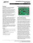
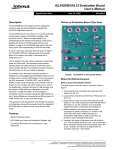
Using The Board (Refer to Figure 2)
Lab Equipment
The equipment, external supplies and signal sources
needed to operate the board are listed below:
1. +1.8V to +6.5V DC Power Supply
3. Connect the Audio Signal Oscilloscope to the COMx BNC
outputs.
4. Connect the Logic Control generator to the INx logic
inputs.
5. Set the EN pin to logic “HIGH” to have the switches
active.
NCx Switches Active
2. Audio Signal Generator
3. Audio Signal Oscilloscope
1. Drive the INx pins to logic “LOW”.
4. Logic Control Generator and/or Pulse Generator
2. The NCx switches are now connected to the COMx
terminals.
Initial Board Setup Procedure
1. Attach the evaluation board to the DC power supply at J1
(VCC) and J2 (GND). Positive terminal at J1 and negative
terminal at J2. The supply should be capable of delivering
+1.8V to +6.5V and 100µA of current.
2. Connect the Audio Source Signal to the NOx or NCx BNC
inputs . The analog input voltage range can be from
VCC-6.5V up to VCC.
3. The NOx switches have shunt resistors on the terminals
to ground.
NOx Switches Active
1. Drive the INx pins to logic “HIGH”.
2. The NOx switches are now connected to the COMx
terminals.
3. The NCx switches have shunt resistors on the terminals
to ground.
Intersil Corporation reserves the right to make changes in circuit design, software and/or specifications at any time without notice. Accordingly, the reader is cautioned to
verify that the Application Note or Technical Brief is current before proceeding.
For information regarding Intersil Corporation and its products, see www.intersil.com
4
AN1370.0
February 3, 2009