1
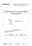
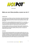
DC MOTOR CONTROLLER
Things to be aware of
with your new Speed
Controller!
1.
The controller has limited
protection against reverse
polarity! If you hook it up
incorrectly, you may render the
device unusable.
2.
The voltage jumper is set by
default at 12-24V, if you plan to
run 24v-48v you will need to
correctly set the jumper.
3.
Double check all connections
before applying power and always
turn off the power supply before
making any wiring changes.
4.
Unless you have the Mosfet isolation
User Manual
Connecting the Speed Control
The connections to the speed control are
The controller has a few settings that
straight forward. Just use the illustrative
need to be addressed prior to first power
diagrams on the next page for your
up!
reference.
Please make sure you SET THE
It is beneficial for currents over 25A to
VOLTAGE JUMPER to the voltage range
utilise both of the terminals (even applying
you plan to use.
links between the connections helps) but
make sure your wiring is capable of
carrying the current your application
requires or the links will serve no purpose.
wires brush against the case, or
that the case is earthed.
If the motor makes an audible noise, you
can lessen or remove this by adjusting
Speed Controller, it’s always good practise
the frequency trim pot (VR3) until the
to add a fuse between the Positive (+)
noise is reduced or gone.
Battery and the motor. Use a fuse rated
slightly higher than the current your motor
If you have any queries regarding your
draws.
new controller please feel free to contact
your place of purchase for help and
The speed controller works by switching the
negative terminal of the Battery to the
Negative input of the Motor very quickly
(PWM). It does not change the voltage at
Warranty:
all, i.e. if your supply input is 12V, then your
All controllers are naturally covered by a
output from the Speed controller will also be
warranty against defects in manufacturing
12V regardless of the motor speed setting.
for one year. If there is a manufacturing
This is a more efficient way of varying a
defect - then we will repair it, free of charge.
resistive load like a motor without losing
Unfortunately there are some failures that
when you change the voltage (VR2)
While it is not necessary for operation of the
option, the motor (-) is ground to the
case chassis. Ensure no stray
You may need to adjust the start position
support.
In standard form, this speed controller is
NOT insulated, meaning if you have the
case earthed on a common ground, the
controller will be constantly on, and will
not vary the speed. This is due to the
metal case used on the controller acting
as a bridge.
torque or efficiency.
are not caused by manufacturing defects
but are due to motor or wiring issues and
problems outside the controller.
This type of failure is not caused by a fault
in the controller and is therefore not under
warranty!
Unless you explain how you consider the
failure to be under warranty we have to
assume you have abused it or
The voltage jumper is by default set at
12-24V, If this is not the voltage you need
please make sure you CHANGE it
Always add wire links as shown if the current is above 25 Amps!
This helps carry current for loads greater than 25 Amps.
Speed Control Connections:
(1) Motor or HHO Negative Terminal (To the Motors Negative – connection)
(2) Link to (1) to help carry high currents (shown above)
(3) Link to (4) to help carry high currents (shown above)
(4) To the Battery Negative – Terminal
(5) Positive goes to the Battery Positive Terminal (This can be a thin wire, it’s
not a load carrying wire)
This shows the internal connections and adjustments of the speed controller.
This is looking at the controller case internals
Please note: On the 12-36V controller the highest voltage is 36V, only the
12-48V Version will go up to 48 Volts!
Note that on standard controllers 40V is the uppermost limit!
After this point the standard controller will fail.