1
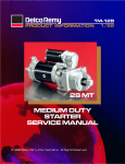
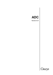
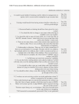
Chassis Mount
PTO Generators
OWNERS MANUAL
INSTALLATION AND OPERATION INSTRUCTIONS
ECV2510-3
ECV2512-3
SIDE VIEW
TOP VIEW
Note: Unit shown is the ECV2512 the only
dimension that changes on the ECV2510 is
the location of the input shaft
DRIVE END VIEW
SAFETY FIRST
READ THIS MANUAL BEFORE OPERATING YOUR GENERATOR.
60706-130
Read and understand all instructions in this
manual before starting and operating the
generator set.
USING THIS MANUAL
PROPER USE AND INSTALLATION
Congratulations on your choice of a Winco generator.
You have selected a high-quality, precision-engineered
generator set designed and tested to give you years of
satisfactory service.
To get the best performance from your new generator, it
is important that you carefully read and follow the operating
instructions in this manual.
Should you experience a problem please follow the
“Things To Check” near the end of this manual. The warranty
listed in this manual describes what you can expect from
WINCO should you need service assistance in the future.
You must be sure your new generator set is:
*
Properly serviced before operating
*
Operated in a well ventilated area
*
Exhaust gases are dispersed safely
*
Wired by a qualified electrician
*
Operated only for its designed purposes
*
Used only by operators who understand its operation
*
Properly maintained
TABLE OF CONTENTS
INTRODUCTION
GUIDE TO PRODUCT SAFETY
BASIC INFORMATION
Description
PREPARING THE UNIT
Unpacking the unit
Assembly
INSTALLATION
Plan the Installation
Mounting
Ventilation
Drive Line & Lubrication
Pre-Wire Checklist
Initial Start
ELECTRICAL CONNECTIONS
FINAL SYSTEM CHECK
MAINTENANCE
General Information
Periodical Maintenance
Generator Maintenance
Lubrication
TROUBLE SHOOTING TABLE
PART LIST
Automatic Voltage Regulator
Generator Parts List
Gear Box Part List
WIRING DIAGRAM
12 MONTH WARRANTY
i
1
2
2
2
2
3
3
3
4
4
4
5
5
5
5
7
8
9
10
12
13
14
COPY YOUR MODEL AND SERIAL NUMBER HERE
No other WINCO generator has the same serial number as
yours. It is important that you record the number and other
vital information here, if you should ever need to contact us on
this unit it will help us to respond to your needs faster.
MODEL____________________________________
SERIAL NUMBER____________________________
PURCHASE DATE____________________________
DEALER___________________________________
3.
SAFETY INFORMATION
This generator set has been designed and manufactured to
allow safe, reliable performance. Poor maintenance,
improper or careless use can result in potential deadly
hazards; from electrical shock, exhaust gas asphyxiation, or
fire. Please read all safety instructions carefully before
installation or use. Keep these instructions handy for future
reference. Take special note and follow all warnings on the
unit labels and in the manuals.
a.
b.
4.
b.
5.
b.
d.
Use only factory approved replacement parts.
Do not work on this equipment when fatigued.
Use extreme caution when working on electrical
components. High output voltages from this
equipment can cause serious injury or death.
Always avoid hot mufflers, exhaust manifolds, and
engine parts. They all can cause severe burns
instantly.
ELECTRIC SHOCK- The output voltage present in this
equipment can cause a fatal electric shock. This
equipment must be operated by a responsible person.
INSTALLATION- Installing a PTO generator is not a “do-ityourself” project. Consult a qualified, licensed electrician
or contractor. The installation must comply with all
national, state, and local codes.
a.
a.
b.
c.
d.
e.
f.
g.
2.
Remove all grease, ice, snow or materials that
create slippery conditions around the unit.
Remove any rags or other material that could
create potential fire hazards.
SERVICING EQUIPMENT- All service, including the
installation or replacement of service parts, should be
performed only by a qualified technician.
a.
b.
c.
7.
1.
Use hearing protection equipment when
working around this equipment for long periods of
time.
Keep your neighbors in mind when permanently
installing this equipment.
CLEANLINESS- Keep the generator and surrounding area
clean.
a.
6.
Operate only in well ventilated areas.
Never operate indoors.
NOISE HAZARD - Excessive noise is not only tiring, but
continual exposure can lead to loss of hearing.
a.
ANSI SAFETY DEFINITIONS
______________________________________________________
DANGER:
DANGER indicates an imminently hazardous situation which,
if not avoided, will result in death or serious injury. This signal
word is to be limited to the most extreme situations.
______________________________________________________
______________________________________________________
WARNING:
WARNING indicates a potentially hazardous situation which, if
not avoided, could result in death or serious injury.
______________________________________________________
______________________________________________________
CAUTION:
CAUTION indicates a potentially hazardous situation
which, if not avoided, may result in minor or moderate injury. It
may also be used to alert against unsafe practices.
______________________________________________________
NOTE:
CAUTION is also used on the unit labels and in this
manual to indicate a situation that could result in serious
damage or destruction of the equipment and possible
personal injury.
______________________________________________________
DEADLY EXHAUST GAS - Exhaust fumes from any engine
contain carbon monoxide, an invisible, odorless and
deadly gas that must be mixed with fresh air.
Do not allow anyone to operate the generator
without proper instruction.
Guard against electric shock.
Avoid contact with live terminals or receptacles.
Use extreme care if operating this unit in rain or
snow.
Use only three-prong grounded plugs and
extension cords.
Be sure the unit is properly grounded to an
external ground rod driven into the earth.
Do not make or break electrical connection under
load.
b.
c.
8.
OPERATION - PTO drive shafts (Tumbling Bars) have
many inherent dangers, extereme caution must be
exercised when using them.
a.
FIRE HAZARD- Gasoline, diesel and other fuels always
present a hazard of possible explosion and/or fire.
b.
a.
c.
Keep a fire extinguisher nearby and know its
proper use. Fire extinguishers rated ABC by
NFPA are appropriate.
d.
e.
f.
60706-130
Page 1
Never operate the PTO drive generator without having
it properly mounted.
Never connect the PTO generator to an existing
electrical system without installing an isolation
transfer switch.
Always insure the drive shaft is straight and level
before operating the generator.
NEVER allow children around a drive shaft when it is
in operation.
Keep all safety guards and shields in place and
securely tightened.
Never operate a drive shaft that has been damaged
or had the safety shield removed.
Never step over a drive shaft while it is running.
Never wear a necktie, loose articles of clothing, or
anything else that can be caught in moving parts.
Never try to stop a turning drive shaft with your hand
or your foot.
7150-01
DESCRIPTION
The WINCO ECV2510/2512 PTO drive generator will
provide 120/240V single phase, 60Hz electrical service
when direct-driven. The ECV2510 requires a 1000 RPM
input shaft speed and the ECV2512 requires a 1182 RPM
input shaft speed.
NOTE: The prime mover which drives the generator must
be capable of delivering approximately 2 HP per 1000
watts output from the generator. Observe input RPM
specifications.
When loss or damage is noted after delivery, segregate
the damaged material, and contact the carrier for claim
procedures.
“Concealed damage” means damage to the contents of a
package which is not evident when the package is delivered by the carrier, but which is discovered later. The
carrier or carriers are responsible for merchandise lost or
damaged in transit. The title to the goods rests with the
consignee when the goods are shipped FOB factory, and
only the consignee can legally file claims. Two years are
allowed in which to file suit after a claim is disallowed in
writing by the carrier.
The generator may be under chassis mounted and driven
from a truck transmission with a PTO drive installed in it.
This generator is a rotating armature design with compound field coil windings. Normal excitation is accomplished via the "Q" winding in the armature and a full wave
bridge rectifier. An automatic voltage regulator is installed
on the generator to maintain the correct voltage when the
unit is under load.
To reduce maintenance problems, the coupling between
the generator input shaft and rotor consists of precision
helical gearing rather than a chain link drive. The input
shaft is 1-1/8 in diameter smooth shaft with a key way and
center drilled for a roll pin. Both must be used at all times.
WINCO thoroughly tests each of these generators before
shipment. All are continuous duty rated.
IMPORTANT: THE MANUFACTURER STRONGLY
RECOMMENDS RUNNING THE GENERATOR UNDER
LOAD AT LEAST ONCE A MONTH IN ORDER TO EVAPORATE ANY ACCUMULATED MOISTURE CONDENSATION
INSTALLATION
********************
********WARNING* *********
*********************
Before proceeding with the installation, be sure the drive
line and engine are disabled and cannot accidentally
operate while the generator is being installed.
Before beginning the installation process recheck the voltage
power rating and physical size and drive line rating and
speed, horsepower etc. Be certain they can handle the
intended load and are compatible with the required vehicle
equipment voltage, phase and current ratings. Plans for
installation should be prepared with proper attention to mechanical and electrical engineering detail to assure a satisfactory system installation. The information in this manual is
offered as a guide to finalizing your installation plans. The
installation sequence is summarized below:
A.
Plan the installation :
1. Space required for installation and service
access.
2. Protected location, close to electrical connections.
3. Mounting frame.
4. Clear of moisture and dirt.
5. Shielded from excess heat and cold.
B.
C.
D.
E.
F.
G.
H.
Mounting the generator system.
Clear, protected source of ventilation of generator.
Drive line aligned within 5 degrees (10 degrees max).
Pre-wire system check.
Initial system start-up.
Generator electrical power connections.
Final system check
UNPACKING
CAUTION: Equipment Damage
DO NOT invert generator during unpacking. The Gearcase contains oil which will leak out if inverted during
unpacking.
Unpack the generator as follows:
1. Remove the carton.
2. Inspect the generator carefully for freight loss or damage. If loss or damage is noted at time of delivery,
require that the person making the delivery make note
of the loss or damage on the freight bill, or sign the
consigner’s memo of the loss or damage. Contact the
carrier for claim procedures.
3. Remove the four bolts which hold down the generator
feet to the pallet.
4. Lift the generator from the pallet by means of the lifting
eye on the top of the generator.
7150-01
A. PLAN THE INSTALLATION
1. Space Required. The space required should allow for
ample working room around and in back of generator.
A general rule to follow is 12 inches minimum clearance all around the unit. This allows a service person
to repair and remove generator parts in the event
service is needed. In general, all service can be
performed from the rear generator cover or the front
gear case.
Page 2
60706-130
2. Location. Locate as close to electrical service as possible. This will reduce the cost of electrical and minimize
the losses in the power conductors. Position the unit to
keep clear of the drive line and exhaust runs.
3. Mounting Support. Frame loading, frame type and
strength should be taken into consideration when
installing an emergency rescue generator under a
truck.
4. Moisture and Dirt. Protection from adverse weather
conditions and road spray must be provided without
restricting adequate ventilation for cooling. All
electrical equipment should be protected from
excessive moisture. Failure to do so will result in
deterioration of the insulation and will result in short
circuits and grounds. Foreign materials such as
dust, sand, tint and abrasive materials have a
tendency to cause excessive wear, particularly the
brushes. It is important that the unit be installed in a
reasonably clean location for best service life. Careful
planning will eliminate costly rework.
5. Heat and Cold. All generators radiate considerable heat
when they are running. In addition, these units are
generally mounted in a somewhat restricted location
which precludes natural cooling. Allow space for cooling air to sweep across the generator shell. It is important that the temperature of the ambient air around the
unit not exceed 105 degrees Fahrenheit while operating. Additional cooling louvers or fans may be necessary if adequate cooling flow is not naturally provided.
B. MOUNTING THE GENERATOR SYSTEM
The generator should be bolted solid to a heavy steel
cross channel or plate. It is recommended that the
generator be mounted on a steel sub-frame which
facilitates easy removal of the generator for better service
access to the chassis or for generator repair.
Shock mounting the generator or mounting frame is
generally not recommended do to possible harmonic
vibration, drive misalignment and mounting stress.
Make sure the drive shaft (tumbling bar) is assembled with
its universal joint knuckles “synchronized,” as illustrated in. If
knuckles are not synchronized, the bar will chatter when
rotating, which will cause the generator output voltage to
flicker.
C. VENTILATION OF GENERATOR
This is an air cooled generator. This unit is equipped
with a suction fan to cool the armature and field coils.
Therefore it will be necessary to insure that the hot air
discharge plume gets out of the mounting area.
D. DRIVE LINE AND LUBRICATION
Check gear case oil level. Case should be filled with oil
to plug marked “OIL LEVEL.” Fill or remove oil as required.
NOTE: EITHER TOO LITTLE OR TOO MUCH OIL CAN
HARM THE EQUIPMENT.
See “Lubrication” portion of Maintenance for oil specifications.
60706-130
Page 3
7150-01
The PTO drive shaft should be maintained in as straight a line
as possible. Install the generator so the drive line is aligned to
within 5 degrees (10 degrees Max). The 2510/2512 PTO units
will require about 50 Hp to maintain full output, be sure that
the auxiliary drive on the vehicle transmission and the gear
reduction box is capable of the expected mechanical load. It
is generally recommended that the drive shaft be balanced to
minimize drive line vibration and stress. Make sure no binding
exists in generator or gear box. If binding is found, locate the
cause and correct it before proceeding
*****Notice *****
E. PRE-WIRE SYSTEM CHECK:
G. GENERATOR ELECTRICAL POWER CONNECTIONS
WARNING: Personal Injury
When working on or around these generators, do not wear
loose fitting clothing or any articles that may get caught in
moving parts.
ALL wiring should be done by a licensed electrician, and
should conform to the national electrical code and with state
and local regulations.
Before wiring the generator to the distribution load circuits,
the installation and operation of the drive system and
generator should be checked to insure proper drive line,
engine and generator operation.
Use the following check List to verify correct installation
before starting the engine:
1.
2.
3.
4.
5.
Drive line straight and tight.
Unit mounting base and hardware solid and bolts
properly torqued.
Ventilation clear and protected.
Clearance on all sides and service access on both
ends
Generator output leads protected from grounding.
F. INITIAL START AND TEST PROCEDURE
CAUTION:
Make sure that all tumbling bar lock pins are engaged and
that all safety shields are in place before operating the
PTO generator.
2.
See vehicle manufacturers instructions for operating
procedures. The generator should be turning at
specified rpm and producing correct voltage and
frequency. If the generator fails to operate as specified, stop the engine and refer to the trouble shooting
section of this manual.
With the engine running smoothly, and at the desired
speed, check the no-load voltage and frequency.
Generator leads G1 to G3, should read 240 Volts
nominal(240 TO 255 volts). Leads G1 to GN, and G3 to
GN both should read a nominal 120 volts(120 to 127
volts) at 60 Hz. It may be necessary to adjust the
voltage regulator to obtain the proper voltage. The
voltage regulator is located on the left hand side of the
generator end cover. Final voltage adjustments must
be done on the voltage regulator. The regulator may
not effect the no-load voltage to any degree.
7150-01
After verifying the voltage and frequency are correct, prepare
for final wiring of the generator by disabling the drive system
and or engine. The generator can now be connected to the
load circuits.
The generator power output leads are marked G1(A & B) ,
G3(A & B) and GN(A & B). We use parallel leads from the
generator to reduce the wire size and make them eaiser to
handle. The A & B wires are always paired together.
A main line circuit breaker must be installed in the load
distrubution panel on the vehicle. The G1 and G3 wires are
routed to the mainline circuit breaker in the distribution panel.
The neutral lead GN is run to the neutral terminal in the
distribution panel.
Note! Most codes require that the neutral conductor be
“bonded”’ (grounded directly to the frame of the generator).
Check local codes to insure compliance. Refer to the national
electrical code NEC for portable/ mobile equipment. No
further electrical connections are required.
After completing the above checklist, the generator is ready
for the initial start-up test.
1.
If for any reason during the check-out procedure the
voltage and frequency are not correct, stop the engine and
refer to the troubleshooting procedures.
The load current carrying wires must be sized to handle
the maximum load current without excessive voltage drop.
By NEC code, conductors must be heavy enough to handle
the full current rating of the main line circuit-breaker (or
fuse) in the load distribution panel protecting the conductors.
All wires should be installed in rigid or flexible conduit.
Because of the many different types of wiring service,
feeder, and distribution panels used on rescue equipment,
no specific wiring instructions can be provided.
*************
*****WARNING******
************
If auxiliary (shore/commercial) power may also be connected to the load for demonstration, training or alternate
source power, an isolation switch must be installed. An
isolation switch will prevent feed back of commercial power
into the generator or generator power into commercial line.
When the load is connected to the generator there must be
absolutely no feedback from the generator to the power line
or from the power line to the generator during any operating
condition. When correctly connected, the design of the wiring
control system prevents an possibility of feedback. Improper
installation can create a serious hazard that could result in
equipment damage, serious personal injury or death.
Page 4
60706-130
H. FINAL SYSTEM CHECK
1.
2.
3.
4.
5.
6.
Recheck voltages at mainline circuit breaker. Voltages
should match readings taken at the pre-wire checkout. If problems are noted, consult troubleshooting
section or factory.
Turn on the mainline circuit breaker.
Turn on each load individually first, to insure that each
load will work properly.
Turn on all the loads and recheck voltages. It may be
necessary at this time to adjust the voltage using the
voltage regulator mounted on the generator end cover to
obtain the proper full load voltage.
Turn off all the loads and make sure that the no-load
voltage has stayed within the proper range.
If all voltages and frequencies stay within the proper
range, this completes your initial start up procedure.
is recommended that the generator be operated at least
monthly under normal loads to familiarize operators with the
procedures and controls as well as to dry out any accumulated condensation or other moisture in the generator electrical windings. The maintenance and service attention invested will insure getting the peak performence that was
designed into the unit.
Routine preventive maintenance minimizes costly repairs
and generator down-time. Before each use, inspect the
generator: gear case oil level should be correct, cooling
vents and screens should be clear, and generator mounting hardware should be tight. Clean and inspect the
generator after storing it for long periods, and after using it
in extremely dusty conditions or in severe weather, such as
rain or blowing snow.
Generator Maintenance
OPERATION
A. Brushes
Since the generator is self excited and externally regulated,
there is no need for operational controls for the generator.
Once the regulator is set it should never have to be
adjusted. The vehicle manufacturer will provide operation
manual for the governor operation and control panel
operation.
MAINTENANCE
General Information
The main components of the generator are: armature, field
coils, cooling fan, brushes, brush holder assembly, end
brackets, rectifier and voltage regulator. Before performing
any maintenance on the generator, isolate and/or disable the
drive system so the unit can not be accidentally started while
being repaired.
Under ordinary circumstances, brushes will operate for extremely long periods without requiring replacement. They
should be inspected after the first 500 hours of operation, and
after every 200 hours of operation thereafter. Remove brushes
one at a time and check for length; be sure that each moves
freely in the brush holder. Brushes should be replaced when
worn down to 3/8”. Replace brushes in complete sets, never
singly. When replacing brushes, be careful to reconnect the
lead wires properly.
Poor contact (or “skipping”) between brush and slip ring is
caused by oil and grit, flint, or other hard substance on the
brush, or by the brush not being properly shaped to fit the slip
rings. Remedy these defects by fitting the brushes to the slipring curvature. Place # 00 sandpaper under the brushes with
the abrasive side to the brushes, and work it back and forth
until the brushes are the same shape as the slip-rings.
B. Slip rings
The troubleshooting chart lists various symptoms of poor
generator operation with possible causes and the appropriate corrective action. You will need a volt-ohm meter or
test light to check some of the causes. For some of the
other causes you will need to check generator speed. To
check generator speed you can use a frequency meter, a
tachometer, or a 120V-60Hz electric clock and a correctly
operating wrist watch. (Run the electric clock on generator
power and compare the clock’s second hand movement
with that of the wrist watch. They should run at the same
speed. If clock runs faster, generator speed is too high,
and vice versa.)
CAUTION: Equipment Damage
Most electrical equipment in North America operates
satisfactorily at frequencies between 59 and 61 Hz (cycles
per second.) Operating the generator at frequencies
outside that range may cause damage to the generator
and/or to electrical equipment driven by the generator.
The four continuous copper rings located on the end of the
armature are the generator output slip rings. For proper
generator output, the surface of the slip rings must have a
smooth, shiny, highly polished finish. Normal brush
seating will transfer a shiny black finish that will seat the
copper surface. This finish should not be removed unless
it becomes dull or begins to build up. Under sustained
use, it is advisable to check and if necessary, polish the
ring surfaces with a crocus cloth to maintain the smooth
finish.
C.
Testing generator fields for opens and grounds.
1.
2.
Periodical Maintenance
Service/maintenance items include periodic external physical inspection for missing hardware or damage to mounting
or drive system and checking the oil level in the gear case. It
60706-130
Electrical Testing
3.
Page 5
Disconnect field leads from rectifier.
Set multimeter to read resistance, and connect the meter
leads to the field leads. If field is open, meter will read
infinite resistance (very high ohms). Repair or replace field
if it is open. Typical resistance for these fields vary from
17.1 to 18.8 ohms.
Leaving one meter lead connected to the field, connect the
other meter lead to the field shell. If meter indicates
7150-01
1.
Remove all brushes.
2.
Ground fault test - set multimeter to read high resistance
(meg-ohms).Holding one meter lead against a clean spot
on the armature shaft, touch the other lead to each of the
slip rings (one at a time) while observing the meter. If
meter indicates continuity (any reading lower than one
meg- ohm), the armature is grounded. Dirt between the
slip rings and on the insulator surface can cause grounding. If grounding was indicated, carefully clean all dirt off
the slip rings and their insulators and then recheck it.
Replace the armature if it is grounded and unrepairable.
3.
Open Test. Set meter to read low resistance (R x 1
ohms). Holding one meter lead on surface of slip ring
No. 1, touch other meter lead to surface of slip ring No.
2 while observing the meter. Meter should indicate
continuity (low resistance - less than one ohm is
typical). If the meter indicates open circuit (infinite
resistance) part of armature winding is open. This may
be caused by a repairable defect in the connection at
the slip ring, however generally an open armature will
have to be replaced. Continue reading the continuity
between slip ring No. 2 to No. 3 and No.2 and No.4. All
the slip rings should have continuity to slip ring number
2, the neutral ring.
continuity (any reading -should be infinite resistance). The
field is grounded and should be repaired or replaced. To
determine which of the fields is grounded, cut the connec
tor between the two coils and retest to determine which
coil has the low resistance path.
Testing Rectifiers
4.
Disconnect field leads (F1 & F2) from regulator.
5.
Set multimeter to read resistance, and connect the meter
leads to the field leads. If field is open, meter will read
infinite resistance (very high ohms). Repair or replace
field if it is open. Typical resistance for these fields vary
from 11.2 to 12.1 ohms.
6.
Leaving one meter lead connected to the field, connect the
other meter lead to the field shell. If meter indicates
continuity (any reading -should be infinite resistance) the
field is grounded and should be repaired or replaced. To
determine which of the fields is grounded, cut the connec
tor between the two coils and retest to determine which
coil has the low resistance path.
The field excitation is supplied through a full wave bridge
rectifier. This type of rectifier has four terminals, two AC, a
DC positive and a DC negative.
A rectifier may be tested in the following manner:
1.
Disconnect all leads from rectifier.
2.
Connect the red ohmmeter lead to the positive DC (+)
terminal.
3.
Connect the black lead to each of the AC terminals in turn.
Either a high or low resistance reading will be obtained.
Testing the Armature for Opens and Grounds
7150-01
Page 6
60706-130
4.
Reverse the meter leads, (black lead to the DC POS (+)
and red to the AC terminals, each in turn. An opposite
reading should be observed.
The drive shaft (tumbling bar) requires greasing. Keep the
universal joints in the coupling shaft free from grease and dirt
buildup.
5.
Connect the red ohmmeter lead to the negative DC (-)
terminal.
NOTE:
Do not over lubricate the universal joints.
6.
Connect the black lead to each of the AC terminals in turn.
Either a high or low resistance reading will be obtained.
7.
Reverse the meter leads, (black lead to the DC NEG (-) and
red to the AC terminals, each in turn. An opposite reading
should be observed.
Check each terminal to the case. An open circuit (very high
resistance) reading should be observed. A battery pow
ered test light is used. Follow the same procedures
described above. A good diode element will allow current
to pass to the light in the test lamp when the leads are
connected in the forward direction.
Check the generator gear case oil level before each use of
the generator. Maintain the oil level at oil level plug height.
(See page 3 for oil level plug location.) The generator is
shipped with lubricant in the gear case. Specifications for
gear case lubricant are:
8.
9.
If the rectifier fails any of the above tests, it should be
considered defective and replaced.
API Service: GL-5
Grade: SAE 85W-9O-140
Amount: 1 pint
The following kinds of oil are recommended for use in the
generator gear case: Mobil SAE 85W90-140 API Service GL5, Sunoco/DX XL80W90-140 Kendal Three Star 85W-140,
Amoco 85W140 or equivalent.
CAUTION: Equipment Damage
Condenser Testing
Condensers are built into the generator circuit to minimize
radio interference during operation. If a condenser shorts
out, it will also short out the generator output. To determine
whether a condenser is shorted, stop the generator and
disconnect the condenser lead wire from the brush holder.
Using a multimeter on the R x 100 scale, check the resistance of the condenser. Normal response is a sharp swing
of the meter towards low resistance and then a steady rise
towards high resistance (open circuit). If the capacitor is
shorted it will show as a constant low resistance.
Otherwise, restart the generator without the capacitor connected to recheck the generator for output. If the generator then
provides power, the condenser was at fault and should be
replaced. (If the generator doesn't provide power, the problem
was not caused by that condenser, reconnect the lead wire).
If these tests have not located the trouble, remove the
armature and have it tested for opens, shorts, and grounds
on a growler.
Do not overfill generator gear case. Overfilling causes
overheating and oil seal failure.
Change the oil at least once every six months. Change it
more often if you use the generator in bad weather. Use the
following procedure to change generator gear case oil:
1.
Remove gear case breather. Soak breather in cleaning
solvent, then allow it to dry.
2.
Remove oil level check plug.
3.
Remove the oil drain plug, drain the oil into a clean oil
resistant container, 1 quart or larger. Check the oil for
metal. Fine metal dust in the oil does not indicate
trouble, but metal chips do. Dismantle the gear case and
look for damaged gears if you find metal chips in the oil.
4.
Replace the oil drain plug. Refill the gear case through
the breather port with new oil of the recommended type.
Fill the case up to oil level check plug height. (It will take
about 1 pint.)
5.
Replace the oil level check plug.
6.
Replace the breather.
4. Lubrication
The generator bearings are factory lubricated and sealed,
and require no further lubrication.
The generator input shaft should be cleaned and lubricated
with a thin film of grease before installing the drive shaft and
each time it is removed.
60706-130
Page 7
7150-01
TROUBLE SHOOTING TABLE
SYMPTOM
CAUSE(S)
No output
voltage.
CORRECTIVE ACTION
1. Circuit breaker open.
2. Defective voltmeter.
3. Short circuit in the load.
4. Loose (or broken) wires or
connections in control box.
5. Defective rectifier.
6. Dirty slip rings.
7. Brushes binding in holders.
8. Shorted or open field coils.
9. Shorted or open armature.
Low voltage.
1. Engine speed too slow.
2. Generator overloaded.
3. Inadequate engine
horsepower.
4. Incorrect field excitation.
(No-load output low.)
5. Defective voltage regulator.
1. Reset circuit breakers, replace if defective.
2. Check output with another meter, replace meter if defective.
3. Disconnect the load. Check voltage at cord set.
Check motors, appliances and load leads for short circuit.
Repair short.
4. Remove panel cover and check all wiring and connections.
Tighten and/or repair where necessary.
5. Test rectifier. Replace if defective.
6. Clean and polish. Use 00 sandpaper or crocus cloth,
never use emery paper.
7. Check brushes for swelling; replace defective brushes;
clean brush holders.
8. Measure coil resistance. Replace coils if open or shorted.
9. Measure between slip rings for open or shorts. Replace arm if
defective.
1. Check engine speed. Increase RPM if necessary.
2. Reduce load if it is higher than the rated capacity of the
generator. (See generator nameplate).
3. Generator requires 2 HP/1000 watts output.
4. Check for worn brushes and weak or broken brush springs;
replace as required. Check input AC voltage to rectifier.
Check rectifier output DC voltage to positive DC brush. If no
DC voltage is present at the brush, replace the rectifier.
Check for dirty slip rings. Clean them if they are dirty.
5. Check regulator for output. Repair or replace as required.
High voltage.
1. Engine speed too fast.
1. Check engine speed for correct input RPM.
2. Voltage regulator set too high. 2. Have qualified service technician adjust the regulator.
Output voltage
flickering or
fluctuation.
1. Tumbling bar (coupling shaft) 1. Reduce tumbling bar misalignment to less than 15 degrees.
misalignment.
2. Engine speed not constant.
2. Engine governor may be worn or improperly adjusted. Set or
repair defective governor.
3. Tumbling bar U-joints not
3. Reassemble tumbling bar.
synchronized.
Excessive
vibration.
1. Power take-off misalignment 1.
excessive.
2. Loose mounting nuts and bolts 2.
or hold-down studs.
3. Universal joints in coupling
3.
shaft worn or dry.
4. Defective bearings.
4.
Correct misalignment. It should be less than 15 degrees.
Tighten mounting nuts and bolts; repair hold-down stud
mountings.
Repair or replace defective parts.
Check for possible causes. Replace defective bearings.
Generator
overheating.
1. Poor ventilation.
2. Generator overloaded.
3. Shorted turns in field or
stator windings.
1. Clean ventilation and cooling fan screens.
2. Reduce load, then check voltage and current.
3. Replace defective components.
Oil leak.
1. Loose plug in gear case.
2. Defective seal, gasket, or
plug in gear case.
1. Tighten plug.
2. Replace seal(s), gaskets or plugs. Maintain correct oil level.
.
7150-01
Page 8
60706-130
AUTOMATIC VOLTAGE
REGULATOR ASSEMBLY
REF
DESCRIPTION
QTY
PART NBR
001
002
Voltage Regulator
Mounting Bracket
1
1
98884-002
64790-000
003
004
Grommet
Machine Screw
1
2
9336-000
16165-000
005
006
Lockwasher
Flat Washer
2
2
484-000
598-000
007
008
Hex Nut
Sleeving
2
2
6372-000
64620-002
009
010
Circuit Breaker
Cover
1
1
91286-003
64791-001
60706-130
Page 9
7150-01
GENERATOR ILLUSTRATION
7150-01
Page 10
60706-130
GENERATOR REPLACEMENT PARTS LIST
REF
DESCRIPTION
QTY
001
002
003
Cap Screw 5/16”-18x2 3/4
Lockwasher 5/16”
Lockwasher Split Type ¼”
4
4
3
004
005
006
Machine Screw
Lockwasher 11/16 Int.
Flat Washer
007
008
009
PART NBR.
REF
DESCRIPTION
51101-000
480-000
479-000
420
430
431
Hex Nut
Armature Assembly
Armature
1
1
1
20160-000
64794-000
64794-001
3
1
1
45633-000
40552-000
21867-000
432
Bearing
440
Field Shell & Coil Assembly
441A Field Coil
1
1
1
50215-000
61368-002
64787-000
Lockwasher
Hex Nut 1/2-20
Lockwasher
1
1
2
20039-000
9549-000
636-000
441 B Field Coil
442
Pole Shoe
443
Pole Shoe Retainer
1
2
2
64787-001
43473-000
43474-000
010
011
012
Cap Screw 1/2-13 x 1
Machine Screw
Lockwasher
1
4
5
48178-000
44342-000
6376 -000
444
447
448
1
12
1
61153-001
24981-000
23478-000
013
014
015
Hex Nut 8-32
Machine Screw
Cap Screw 7/16-20 x1 3/4
5
28
7
5113-000
40746-000
43781-000
449
Brush “Q”
460T Brush Rack Assembly
460B Brush Rack Assembly
2
1
1
53949-000
53977-000
53977-001
016
400
401
Cap Screw 7/16 -20 x 1 1/2
Generator
Fan Assembly
1
1
1
54806-000
61367-002
23404-000
462
463
467
Brush Holder
Condenser
Rectifier
12
3
1
23500-002
41221-000
91452-000
411
412
413
End Bracket
Oil Seal
Bearing
1
1
1
51046-003
46912-000
46913-000
468
469
470
Ground Strap
Spacer
Brush Holder Spacer
1
14
2
41387-007
23532-000
52559-000
414
415
416
Retainer Plate
Gasket
Spacer
1
1
1
44318-000
20136-000
20137-000
471
472
491
Mounting Plate
Brush Holder “Q”
End Cover
6
2
1
53975-000
23500-000
55438-023
417
418
419
Pinion Gear
Key
Lockwasher
1
1
1
46545-000
20159-000
20139-000
610
N/I
Base
Wiring Harness
1
1
51147-000
64543-000
Field Shell
AC Brush
Lead Shield
QTY
PART NBR.
N/I - Not Illustrated
TECHNICAL DATA
Generator Specifications:
kW - 20; Volts -120/240; Amps - 83; PH - 1; Hz -60;
Input - 1000/1182 RPM; Generator - 3600 RPM
Resistances:
Field Coils (rectifier circuit) 17.1 - 18.8 Ohms; Excitor Volts - 92, Amps 2.4
Field Coils (regulator circuit) 11.2 - 12.6 Ohms; Excitor Volts - 55, Amps 2.8 (full load)
Armature (Q Winding) .080 - .088 Ohms, (G1 to N & G3 to N) .025 - .0275 Ohms
60706-130
Page 11
7150-01
1000 RPM
1181 RPM
PART NBR.
54661-001
44833-000
20029-000
64562-000
PART NBR
64557-000
N/A
20029-000
64562-000
1
4
1
1
46296-000
1774-000
44832-000
20016-000
64556-000
1774-000
46546-000
20016-000
N/A
N/A
N/A
N/A
REF
130
134
137
138
DESCRIPTION
Gear Box Assembly
Pinion Gear
Seal
Bearing
140
141
142
144
Shaft (Input Drive)
Woodruff Key
Gear (input Drive)
Gasket (Cover)
146
147
148
149
Backing Plate
Safety Shield
Gear (Driven)
Bearing
1
2
N/A
N/A
46546-000
54665-000
150
151
152
153
Gasket
Retainer
Gasket
Retainer
1
1
1
1
46299-000
46295-000
46298-000
46286-000
46299-000
64580-000
N/A
N/A
154
155
156
Snap Ring
Gear Case & Cover (Matched)
Breather
1
1
1
20133-000
54662-000
40716-000
N/A
64558-000
40716-000
157
158
Shaft (Driven)
Roll Pin
1
1
20128-000
4133-000
N/A
4133-000
7150-01
QTY
1
1
1
2
Page 12
60706-130
60706-130
Page 13
7150-01
WINCO CHASSIS MOUNT
PTO GENERATORS
12 MONTH/500 HOUR STANDARD
LIMITED WARRANTY
WINCO, Inc., warrants for 12 months or 500 hours which ever occurs first from date of shipment, that
it will repair or replace at its option, for the original user, the whole or any part of the product found
upon examination, by WINCO at its factory at 225 South Cordova Avenue, Le Center, Minnesota,
or by any factory-authorized service station, to be defective in material or workmanship under normal
use and service.
For warranty service, return the product within 12 months from the date of shipment, transportation
charges prepaid, to your nearest factory-authorized service station or the WINCO factory.
There is no other express warranty. To the extent permitted by law, any and all warranties, including
those of merchantability and fitness for a particular purpose, are limited to 12 months from date of
shipment, and liability for incidental or consequential damages or expenses is excluded. Some
states do not allow limitations on the duration of an implied warranty, and some states do not allow
the exclusion or limitation of incidental or consequential damages, so that above limitation or
exclusion may not apply to you. This warranty gives you specific legal rights; you may have other
rights which vary from state to state.
This warranty is limited to bench labor and parts only, no allowance will be made for travel time, or
removal and reinstallation in the truck body.
This warranty covers only the generator as it was delivered to the Original Equipment Manufacturer.
WINCO does not warrant drive lines, or certain other component parts of the product installed by
others, since such items are warranted by their manufacturers.
WINCO does not warrant modifications or alterations which were not made or authorized by the
WINCO factory and which affect the stability or reliability of the product.
WINCO does not warrant products which have been exposed to misuse and/or negligence or have
been involved in an accident.
WINCO does not warrant products which have been installed in such a manner as not to protect them
from the adverse environmental conditions (water, mud, insects, etc.) or have not been kept clean.
WINCO reserves the right to change or improve its products without incurring any obligations to
make such changes or improvements on products purchased previously.
60706-130
225 South Cordova Avenue
Le Center, Minnesota 56057
507-357-6821