1
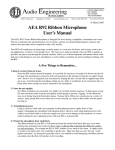
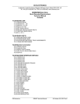
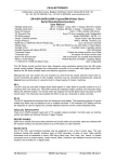
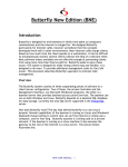
CB Electronics RM-6 Synchroniser Getting Started Guide 2004 CB Electronics Version 1.1 SR/MR CB Electronics has made every effort to ensure the accuracy of information contained within this document, which is nevertheless supplied for information purposes only and does not constitute any form of warranty or guarantee. All trademarks acknowledged. The information in this document is subject to change without notice. CB Electronics Loddonside, Lands End House Beggars Hill Road Charvil Berkshire RG10 0UD Tel: +44 (0)118 9320345 Fax: +44 (0)118 9320346 Email: [email protected] Tech Support: +44 (0)118 9320345 CB web site: www.colinbroad.com This guide will introduce the RM-6 synchroniser-controller . The user guide can be found at: www.colinbroad.com/cbsoft/manuals/sr-user.pdf in English and at www.colinbroad.com/pdf/sruserfr.pdf in French. The technical manual may be found at: www.colinbroad.com/cbsoft/manuals/sr-tech.pdf in English and at www.colinbroad.com/pdf/srtechfr.pdf in French. 2002 CB Electronics SR/MR Contents INTRODUCTION 1 Time synchronisation 2 Digital sample rate synchronisation 3 INSTALLATION Connecting Machines OPERATION 4 4 6 CONTROLLING MACHINES FOR THE FIRST TIME 6 MAKING A TEST RECORDING ON A SINGLE MACHINE 7 CONTROLLING MULTIPLE MACHINES 8 Defining the Master 8 Defining Slaves 8 Entering an Offset 9 Defining Offsets: Chase Here 9 SYSTEM SETUP 11 CHOSING THE CORRECT CB SYSTEM 13 MR OR SR 13 RM-6 13 SR-4 AND SR-424 13 SR-24 AND SR-32 14 RM-6-4 AND RM-6-24 14 GRAPHICAL USER INTERFACE 14 XMC 15 GLOSSARY 2002 CB Electronics 16 SR/MR Introduction The RM-6 Controller/Synchronisers are designed to control and synchronise multiple machines simultaneously. The RM-6 will recognize most Sony protocol machines and automatically configure themselves for the connected machines. Either the SR’s synchroniser or the built-in chase features of modern machines can be used for device synchronisation. • 1 U Rack mounting unit with 6 Serial Ports • • Optional Front Panel Control including setup and transport control May be used with Sr-4, SR-24, SR-32, SR-424 or Custom keyboards and/or CBServer Software. • Simple RS-422 serial connetion to remote keyboard • • Default serial protocol: Sony P2 protocol. Optional protocols supported include AK ES Bus, Studer TLS400, Studer D820, Timeline LYNX I & II, Ampex, Midi via P2MMC, and Pioneer (DVD) via P2DVD, Biphase via BS-1/2 or MC-1. • Plug and play auto-configuration for Sony P2 compliant machines and many other RS422 controlled devices • Support for simultaneous multiple record/un-record commands • Virtual Machine Mode – Perfect Machine as Tapeless Master • • Timecode output follows master position and offset Separate Play Timecode Output (Master is in locked forward play) for automation/outboard systems • Timecode input for lock machines to remote code source or as timecode reader that may be assigned to any machine. • GPI’s: 6 parallel outputs and 6 parallel inputs • Biphase Output via BS-1/2 - for projector and sep mag sound. • • Parallel remote control ‘S29 Remote’ with Commands and Tally’s. Biphase Input Option via FC-1 - slave multiple Video Recorders to a telecine. 2004 CB Electronics 1 Version 1.1 SR/MR Figure 1: RM-6 block diagram The RM-6 has six 9-pin ports to control up to a maximum of five machines. Port E may be configured as an input or output. Port F is always an input. CB Electronics equipment has been described as digital glue for film and TV post sound. Applications are wide ranging and include tape or hard disk based video and audio post production, film sound synchronisation, sound dubbing and DVD mastering Time synchronisation The Video and Audio Post Production process requires the playback and record machines involved to be kept in controlled time synchronisation. This can be achieved using SMPTE/EBU timecode, MIDI timecode, RS422 position or Biphase clock. Timecode was devised by the Society of Motion Picture and Television Engineers (SMPTE) to enable synchronisation between video and audio devices. The resulting standard was also adopted by the European Broadcasting Union (EBU). The original ‘longitudinal’ version or LTC records clock information divided into hours, minutes, seconds and frames as a separate audio track onto tape along with the video or audio signal. VITC or Vertical Interval Timecode takes advantage of the ability of video machines with rotating heads to read thye timecode at low speed or stop. This allows position information to be available even when the tape transport is stopped. 2004 CB Electronics 2 Version 1.1 SR/MR The SR controllers have been developed from the MR remote control system using RS422 control and synchronisation facilities to enable video, audio and film equipment to be kept in time synchronisation. It is normal in a synchronised system to provide a master video reference to the system and for one machine such as a video recorder to be Master and all others to be Slaves or ‘Chase’ machines. A time offset may exist between the Master and one or more Slave machines depending on the ‘start’ timecode chosen when the playback material on the ‘Slave’ was created. Digital sample rate synchronisation Digital audio has the further requirement that the digital data sample rate is kept in step throughout the digital process. Digital data rate synchronisation requires that all digital audio machines be supplied with a sample rate reference such as wordclock or digital silence or a reference from which a sample rate can be derived such as video. Clicks and pops will result in recordings unless the same sample clock rate and phase is maintained in a system. When Wordclock is used as the machine reference and not video sync the machine must be slaved to timecode for absolute phase accuracy as there are approximately 2000 samples in one timecode frame. A Rosendahl nanosyncs or similar reference generator may be used to supply wordclock and video syncs from the same reference crystal or derive wordclock from a video sync source. 2004 CB Electronics 3 Version 1.1 SR/MR Installation All CB systems have a similar architecture; this document describes the RM-6 installation. The RM-6 is housed in a 1U 19 » Rack unit’. Connecting Machines The controlled Machines are connected to ports A to E on the RM-6 using standard 9 pin cables (SR-Tech T5.03). Figure 3: RM-6 exemple System using the XSR-4 as a remote control Port E on the RM-6 may be connected to a controlled machine only if Port E has been configured as an output port in the set-up. Note that the pin-out of port E 2004 CB Electronics 4 Version 1.1 SR/MR is configured by 4 links inside the unit, it may be necessary to use a Tx-Rx invert lead SR-Tech T5.04). Figure 4: RM-6 Input and Output connectors Video syncs MUST be connected to the RM-6 and to all video machines, the system will not work correctly without an appropriate reference. Audio machines may be used with wordclock and master timecode instead of video syncs. Ensure that timecode is connected from the RM-6 to any machines that have built-in synchronisers and to any outboard equipment that needs timecode. The Play output should be used when connecting outboard equipment that is confused by Stationary Timecode. Tip: It is preferable to use a distribution amplifier to distribute timecode. Tip: It may be preferable to use the Separate locked-play timecode output of the RM-6 for any machine or outboard equipment that will not read stationary timecode Connect Power to the RM-6 and power all connected machines. The RM-6 will attempt to recognize and auto-configure for all known devices. The name and current position of each machine should be displayed on the left of the LCD display. If the incorrect name is shown, then the SR unit will not configure correctly. Check the machine set-up as some machines have selectable ID. Refer to section T4 of the SR-Tech Manual for further help. For connector pin-outs refer to section T5.00 of the SR-Tech Manual. Machines may be selected and controlled as explained in the Operation chapter once configuration is complete. Please contact your CB retailer or email [email protected] for help with new or un-recognized machines. 2004 CB Electronics 5 Version 1.1 SR/MR Operation The RM-6 front panel provides access to all the available machine commands and synchroniser features.. Figure 5 RM-6 Fron Panel Controls Controlling machines for the first time To use without a frontpanel access is available only from the remote control see the SR-4 manual for further information. The five keys labled A to E are used to select individual machines The name and current position of the selected machine will be shown on the upper left of the LCD display. If any machine is not recognised refer to the Installation chapter for further help. The Key labled [CMD] switches the left keyboard between Command keys or Numeric keys. The [CMD] key may be locked using [Shift] followed by [Cmd}.. The timecode reader is selected by depressing keys [A] and [B] symultaineously. The timecode Generator is selected by depressing keys [D] and [E] symultaineously. To confirm proper machine control proceed as follows: 1. Select a recognised machine. 2. Ensure that the selected machine is remote enabled. 3. Depress the play key; the machine should enter play, check that the timecode display is correct. 4. Depress the stop key, the machine should enter pause. 5. Enter a valid timecode number. 6. Depress the Locate key. 7. When the locate point is reached, the locate key illumination is cancelled and the Stop key will be illuminated. 2004 CB Electronics 6 Version 1.1 SR/MR The selected machine should locate to the timecode position entered or to ‘pre-roll’ before the entered position. The user may select to locate with or without pre-roll. Alternatively using Shift followed by Locate will reverse the user selection. This demonstrates one of the main principles of operation, enter the timecode number first, and then press the appropriate action key. Note: The Locate with Pre-roll is defined in system set-up: Unit\ Generic \ Locate with Pre–Roll. Making a test recording on a single machine Before a recording is made the selected record machine must be Record Enabled and chosen record tracks must be Track Armed or ‘Record Readied’. To Record Enable a machine, Stop the system then hold down the Record button and select a machine (in Stop mode) using one of the green machine select buttons (A to D). Whilst the Record key is down the machine select LED's indicate the current record enable status of the machines. To record - ready one or more tracks, press one or more of the Track Arm buttons. If no remote control is connected it is not possible to track arm machines directly from the RM-6. Either connect a Remote or use CBServer software. Note: When fitted the Bank macro button provides access to further tracks on multitrack machines with more than eight tracks up to a maximum of 48. Refer to the SR/MR Serial Remote/Synchronisers User Manual section 2.07 for further details. Now that a machine has been selected, record readied and tracks have been selected for record, a test recording can be made. To make a test recording using the SR3/4 as a simple controller with a single record readied and track armed machine proceed as follows: 1. 2. 3. 4. 5. Select a machine Ensure the machine has appropriate video or audio inputs Press Play – wait for the ‘Lock’ tally in the display then press record Press Play again to exit record mode Press ‘Stop’ to stop the machine If the recording has been successful the recording it may be reviewed by locating to the in-point and pressing play. 2004 CB Electronics 7 Version 1.1 SR/MR Note When the Record key is depressed the in point will be marked transferred to the keyboard displayed. Depressing the locate key after a recording will locate the in point. There is a 64 Mark store built into the system, the <- and -> keys may be used to select different mark points. Controlling multiple machines Ensure that timecode, video syncs and wordclock have been connected correctly as described in the Installation chapter. When multiple machines are controlled, one machine is normally chosen to be a Master machine with the rest of the machines acting as Slaves or Chase Machines. Locate commands are then sent only to the Master and the Slaves literally ‘chase’ or follow the Master. This is the reason why accurate time sync information such as video reference or timecode is supplied to all machines. Defining the Master Any machine on the system may be defined as the master including the timecode generator or reader. The master is the machine over which the user has total control. Reasons for selecting a particular machine as master include the following: • Film because it is the slowest • • Video so that the user can jog the picture directly The record machine so that it is the first to lock • • A machine that slaves badly or not at all The timecode generator as a ‘Perfect Machine’ • The timecode reader where the master is not directly controlled The term ‘Perfect Machine’ or ‘Virtual Master’ is used for a timecode generator as master since there are no timecode dropouts and locates are instant. To define a master machine proceed as follows: • • Press the Shift key Press a machine key (A, B, C, D, E, Reader or Generator) within 5 seconds • The machine key LED will flash when selected to indicate its Master status Note: The system will only operate correctly if the selected master is resolved (locked) to video syncs. Defining Slaves 2004 CB Electronics 8 Version 1.1 SR/MR To select a machine as a slave proceed as follows: • Select the machine (A, B, C, D) • • Press the Chase/Offset key The Chase/Offset key will illuminate • The Master key will illuminate and flash, all other slave machine LED’; will illuminate. Note: To take a machine off-line (cancel slave status) repeat steps 1 and 2 in the above procedure and the Chase/Offset key illumination will be cancelled. To disable/enable the chase group select the Master and depress the Chase/Offset key. Entering an Offset The next task is to decide on the timecode Offsets for the Slave or Chase machines. An Offset is the positional difference expressed in timecode values between a location on the master machine and a specific location on the slave. This will only be 00:00:00:00 if the timecode values are identical. To enter an offset proceed as follows: • Select the machine (A, B, C, D, E) • • Type in the required offset The offset is shown in the lower right hand of the LCD display • • Press the Store key – the Store key illuminates Press the Chase/Offset key within 5 seconds – the Store key illumination is cancelled The display will provide confirmation by showing the offset in the upper right of the LCD display whenever it is not zero. Defining Offsets: Chase Here When the Master and Slave are both located at the required ‘in-points’, it may be easier to have the SR/MR calculate the required offset: • Select the machine (A, B, C, D, E) • • Press the Shift key – the Shift key illuminates Press the Chase/Offset key within 5 seconds – the Shift key illumination is cancelled and the slave chase key will illuminate The current Master and Slave positions are used to calculate the Slave Offset as follows: Offset = Master Timecode – Slave Timecode 2004 CB Electronics 9 Version 1.1 SR/MR Note: Transport commands to any chase-enabled (slave) machine such as Play, Stop, Wind, Shuttle and Jog are always redirected to the master. Only Record, Track Arming and Offset commands can be sent to Slave machines. 2004 CB Electronics 10 Version 1.1 SR/MR System Setup Many of the RM-6 functions are defined using the setup menus. The following section provides an introduction to the powerful commands available. Once a connected machine is identified correctly the machine interface software (IFace) parameters will be set up automatically. The setup for the machine may then be customised and any changes will be stored in battery backed RAM until a hard reset or a different machine is connected to the port. There are three setups available • The same as the last time used, volatile stored in battery backed RAM • Factory Setup, Non volatile • User Setup, Non Volatile user adjustable setup The user can select between these setups from the Setup / Unit / Generic / Macro Protection Menu The range of machines that can be auto-configured is constantly updated and the most up to date software may be downloaded from our web site www.colinbroad.com. After switch-on and entering setup, the Root Menu will be displayed, at other times entering setup will access the last menu displayed. To leave the setup menu use the [Setup] key from the Root Menu, if not in the Root Menu, the first depression of the [Setup] key will return to the Root Menu, a second depression of the [Setup] key will exit Setup. The SR/MR Setup menu is split into three sections: MENU 01:- ROOT: Select Setup Required 0= Unit, 1= Auto/ADR 2= Iface 3=Ext 0 UNIT Global, non-machine specific, system operation parameters 1 AUTO/ADR Auto Record/ADR Loop entry and Option selection 2 IFACE Configure currently selected serial port protocol and its connected machine control parameters 3 Ext Configure the Sony 9-pin input options 2004 CB Electronics 11 Version 1.1 SR/MR Note: Once setup is entered it is not possible to change the selected port. Whilst the setup mode is active the Setup LED will be illuminated. Once within the setup menu the key functions are modified as follows: [0] – [9] Select next menu or the setting within the current menu Store Save the current setting and select Next menu Recall Save the current setting and select Previous menu Setup If the ROOT MENU is displayed then exit Setup if any other menu is displayed then Goto the ROOT MENU Figure 6 SR3/4 Setup menu structure Note: Windows overview software is now available to simplify Track Arming and System Setup. 2004 CB Electronics 12 Version 1.1 SR/MR Chosing the Correct CB System All CB systems are built from the same components and have the same user interface; systems may be upgraded by purchasing extra components and software upgrades. MR or SR The basic hardware of the MR and SR systems is identical; the main difference between the two is the expansion possibilities built into the MR system. The MR system uses one serial port as an expansion port enabling the system to be fitted with up to 18 Machine ports, 64 GP inputs, 64 GP outputs and a serial interface to the Video Streamer (in video Timecode Display and cueing system). The SR system has a maximum of 5 Machine ports, 6 GP inputs, 6 GP Outputs. RM-6 The RM-6 is a 1U Rack mounting Hub normally installed in the machine room, the optional front panel display and keyboard allow the system to be controlled in the machine room whist testing, setting up, or fault finding the system. Any of the SR/MR keyboards may be used with the RM-6 using the CB Xmc protocol, the remote keyboards are fitted with either 2 or 4 ports, port B is used to connect to port F on the RM-6, the other ports are used as one or three inputs to the system. Multiple independent remotes may be connected to the system. The RM-6 has 6 serial ports and may be used with the SR-4, SR-24, SR-32, SR-424 or custom keyboards. SR-4 and SR-424 Four port self contained systems containing keyboard, display, and synchroniser. Advantages • Lowest cost • Small compact remote with keyboard and display 2004 CB Electronics 13 Version 1.1 SR/MR • Single Self Contained unit • 2 line 40 character 5mm tilting display Disadvantages • All cables have to be connected directly to the remote control • Maximum of 4 ports SR-24 and SR-32 Four or Six port systems with keyboard and combined display/hub. Advantages • Low profile keyboard with 24 character LED display • Single 25 way cable between keyboard and Display • 2 line 40 character 8mm display can be read from a distance Disadvantages • All cables must be connected to the Display • Five metre maximum distance between keyboard and display. • Two separate boxes RM-6-4 and RM-6-24 Six port systems consisting of a RM-6 with either SR-4 or SR424 remotes Advantages • Rack mounting hub may be fitted in machine room • Single 5 way RS-422 cable between keyboard and Hub • 2 line 40 character 5mm tilting display • Self contained remote with both keyboard and display • Optional keyboard and display may be fitted to the RM-6 • Up to 1km between keyboard and Hub Graphical User Interface CB Electronics windows software suit may be run on any Windows 98, 2K, XP computer with a free serial port. The interface may be used in place of or with the two line 40 character LCD 2004 CB Electronics 14 Version 1.1 SR/MR display. We have currently tested the software on the Studer Vista, Soundtracs, Lawo and API consoles. The following functions are provide by the software:: • • Master Position Display Machine Details • Track Arming • • Snapshot cue list System Setup • Macro commands For further details see the Windows Software Suite pdf file on our web site Xmc Xmc is an open source multi-machine protocol developed by CB Electronics. This protocol is available to anyone who wants. Currently used by Harrison and Lawo to provide a multi-machine record interface. The Xmc protocol is used by Harrison for timecode position and system status. 2004 CB Electronics 15 Version 1.1 SR/MR Glossary Master Machine When controlling a group of machines the commands are sent directly to the Master Machine Normally the video or film machine for fine control when jogging. Perfect Machine/Virtual Master The timecode generator when used as the Master machine, called perfect, as there are no timecode dropouts and locates are instantaneous. Slave/chase Machines These machines follow/chase the master machine, the only user commands sent directly to these machines are record, track arming and offset. Offset The positional difference between the master position and required slave normally 00:00:00:00 when the time-codes are identical. Master Position + Master Offset = Slave Position + Slave Offset Difference The difference between the slave machine position and required position including the offset. 2004 CB Electronics 16 Version 1.1