1
User’s Manual
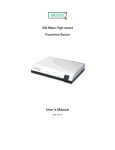
Powerline 85M
Wireless-G Extender
Index
FCC Part 68..............................................................................................................................................................2
FCC Part 15..............................................................................................................................................................3
Chapter 1 Introduction ..............................................................................................................................................4
1.1 Overview ...........................................................................................................................................4
1.2 Features ............................................................................................................................................4
1.3 System Requirements .......................................................................................................................5
Chapter 2 Installation................................................................................................................................................6
2.1 Checklist............................................................................................................................................6
2.2 The Front LEDs .................................................................................................................................7
2.3 The Rear Ports ..................................................................................................................................7
2.4 The Bottom Port ................................................................................................................................8
Chapter 3 Configuration............................................................................................................................................9
3.1 Determine your connection settings..................................................................................................9
3.2 Connecting the Powerline Extender to your network ........................................................................9
3.3 Configuring with Web Browser..........................................................................................................9
3.3.1 LAN Interface Configuration.........................................................................................................11
3.4.1 Wireless Settings......................................................................................................................... 12
3.4.2 Wireless Security......................................................................................................................... 13
3.4.3 Wireless Advance........................................................................................................................ 14
3.4.4 Wireless MAC ACL...................................................................................................................... 15
3.5.1 System Setup .............................................................................................................................. 16
3.6.1 TCP/IP Settings for Windows Operating System ........................................................................ 17
Chapter 4. Powerline Networking Utility ................................................................................................................ 24
4.1 Configuration Utility Setup.............................................................................................................. 24
4.1.1 Installation of the Utility ............................................................................................................... 24
4.2 Windows Configuration Utility ........................................................................................................ 25
4.3 User Interface................................................................................................................................. 26
4.3.1 Main Screen ................................................................................................................................ 26
4.3.2 Privacy Screen ............................................................................................................................ 30
4.4 Diagnostics Screen ........................................................................................................................ 31
4.4.1 About Screen............................................................................................................................... 33
4.4.2 Preferences ................................................................................................................................. 33
4.5 Troubleshooting.............................................................................................................................. 34
4.5.1 When the remote Powerline devices can not connect or access? ............................................. 34
Appendix A Glossary.............................................................................................................................................. 36
Appendix B Cabling / Connection.......................................................................................................................... 43
1
FCC Part 68
This equipment complies with Part 68 of the FCC Rules. On the bottom of this equipment is a label that contains
the FCC Registration Number and Ringer Equivalence Number (REN) for this equipment. You must provide this
information to the telephone company upon request.
The REN is useful to determine the quantity of devices you may connect to the telephone line and still have those
entire devices ring when your number is called. In most, but not all areas, the sum of the REN of all devices
connected to one line should not exceed five (5.0). To be certain of the number of devices you may connect to
your line, as determined by the REN, you should contact your local telephone company to determine the
maximum REN for your calling area.
If the modem causes harm to the telephone network, the telephone company may discontinue your service
temporarily.
If possible, they will notify you in advance. But if advance notice isn't practical, you will be notified as soon as
possible.
You will be advised of your right to file a complaint with the FCC.
The telephone company may make changes in its facilities, equipment, operations, or procedures that could
affect the proper operation of your equipment. If they do, you will be notified in advance to give you an opportunity
to maintain uninterrupted telephone service.
If you experience trouble with this modem, please contact your dealer for repair/warranty information. The
telephone company may ask you to disconnect this equipment from the network until the problem has been
corrected or you are sure that the equipment is not malfunctioning.
This equipment may not be used on coin service provided by the telephone company. Connection to party lines is
subject to state tariffs.
2
FCC Part 15
The modem generates and uses radio frequency energy. If it is not installed and used properly in strict
accordance with the user's manual, it may cause interference with radio and television reception. The modem has
been tested and found to comply with the limits for Class B computing devices in accordance with the
specifications in Subpart B, Part 15 of the FCC regulations. These specifications are designed to provide
reasonable protection against such interference in a residential installation. However, there is no guarantee that
interference will not occur in a particular installation. FCC regulations require that shielded interface cables be
used with your modem.
If interference does occur, we suggest the following measures be taken to rectify the problem:
1) Move the receiving antenna.
2) Move the modem away from the radio or TV.
3) Plug the modem into a different electrical outlet.
4) Discuss the problem with a qualified radio / TV technician.
CAUTION:
Changes or modifications not expressly approved by the party responsible for compliance to the FCC Rules could
void the user's authority to operate this equipment.
Cable connections:
All equipment connected to this modem must use shielded cable as the interconnection means.
Notes:
Operation is subject to the following two conditions:
1) This device may not cause harmful interference, and
2) This device must accept any interference received including interference that may cause undesired
operation.
3
Chapter 1 Introduction
Congratulations on your purchase of an Instant Powerline 85M Wireless Extender. The Powerline Extender is the
perfect option to connect a small group of PCs or small wireless clients. Integrated Wireless to Powerline
networks, the device can extend large coverage and less dead space for your home network.
1.1 Overview
Integrated with 4 10/100M ports, it will very easy to use as a switch, and combine the wireless and Powerline
function inside. Using Powerline and wireless benefit, you can connect the pc to internet in anywhere of your
home..
1.2 Features
z
Internet Access
‧TCP/IP, UDP, ICMP, ARP, RARP, Static IP assignment
z
Standard
‧IEEE 802.3, 802.3u Ethernet standards
‧HomePlug 1.0
‧IEEE 802.11b and 802.11g Wireless standards
z
QoS
‧Prioritized random access, contention-free access and segment bursting
‧CSMA/CA with prioritization and ARQ for reliable delivery of Ethernet packets via Packet
Encapsulation Security Features
z
Powerline Modulation
‧OFDM (Orthogonal Frequency Division Multiplexing) with patented signal processing
techniques for high data reliability in noisy media conditions
‧Supports QAM 256/64/16, DQPSK, DBPSK and ROBO modulation schemes
z
Security
‧Provide 56-bit DES link encryption for Powerline network
z
Wireless Features
‧Support 802.11b/g Wireless Access Point
‧Support 128-Bit and 64-Bit WEP encryption , 802.1x, WPA, WPA2
z
Other
‧High-Speed Powerline adapter with Ethernet interface for fast data transfer over the
existing household power supply
‧The high-speed transfer rates of 85Mbps even make it possible to transmit video in DVD quality
‧No need new wires and use at any power socket with up to ranges of 200 meters
4
z
HTTP Web-Based Management
‧Firmware upgrade by UI
‧Password protected access
1.3 System Requirements
1) Personal computer (PC)
2) Pentium II 233 MHz processor minimum
3) 32 MB RAM minimum
4) 20 MB of free disk space minimum
5) Ethernet Network Interface Controller (NIC) RJ45 Port
6) Internet Browser
5
Chapter 2 Installation
This chapter offers information about installing your router. If you are not familiar with the hardware or software
parameters presented here, please consult your service provider for the values needed.
2.1 Checklist
Check the shipping box carefully to ensure that the contents include the items you ordered. If any of the items are
missing or damaged, contact your local distributor. The contents of your carton may vary depending on your
service provider.
Contents description
1) Powerline Router for home/office use
2) Powerline Router Installation and Operation Guide (this publication)
3) Power Cord
4) Ethernet cable Ethernet category 5 twisted pair cable (6 ft)
Application for this device
6
2.2 The Front LEDs
LED
State
POWER
ON
Description
Press the button to power one the router.
OP
Flashing The router running well.
PL
Flashing When the device detect other Powerline devices
ON
Link
Flashing TX or RX activity
LAN
No Link
1-4
OFF
These four LAN (Local Area Network) ports are where you will connect networked
devices, such as PCs, print servers remote hard drives, and anything else you want to
put on your network.
ON
WLAN
Wireless On
Flashing Data transfer between AP and wireless clients
OFF
No link.
2.3 The Rear Ports
7
Connector
POWER
LAN (1-4)
Antenna
Description
Connect to power cord.
Router is successfully connected to a device through the corresponding port (1, 2, 3 or 4).
If the LED is flashing, the Router is actively sending or receiving data over that port.
There are two kind of connecter, fixed or R/SMA connecter.
2.4 The Bottom Port
Connector
Reset Switch
Description
The reset button, the router restore default settings when press until reboot.
8
Chapter 3 Configuration
3.1 Determine your connection settings
Before you configure the router; you need to know the connection information supplied by your service provider.
3.2 Connecting the Powerline Extender to your network
Unlike a simple hub or switch, the setup of the Powerline Extender consists of more than simply plugging
everything together.
3.3 Configuring with Web Browser
It is advisable to change the administrator password to safeguard the security of your network.
To configure the router, open your browser, type 'http://192.168.16.168' into the address bar and click 'Go' to get
to the login page. Save this address in your Favorites for future reference.
At the Password prompt, the User name is 'admin' and the password is ’admin’. You can change these later if
you wish. Click 'OK' to login.
9
You can use "Quick Setup" to setup the device, and choose the connect mode you prefer.
10
3.3.1 LAN Interface Configuration
You can set static IP address at here..
11
3.4.1 Wireless Settings
Wireless Mode
Support Auto, 802.11b only, 802.11g only, Disable modes.
SSID
The identifier set for the wireless network. You can change the SSID. Only devices with the same SSID can
interconnect.
Channel ID
The channel number is used for wireless network. The channel setting of the wireless devices within a network
should be the same.
12
3.4.2 Wireless Security
The Authentication type supports “Open system”, “Shared key”, “WPA-PSK”, “WPA2-PSK” and
"WPA-PSK/WPA2-PSK".
13
3.4.3 Wireless Advance
You can change some wireless advanced parameters at this page. Keep the setting as the default if you are not
the professional user.
14
3.4.4 Wireless MAC ACL
You can set which wireless client’s MAC addresses is allowed or rejected to link to the router via wireless. For
advanced security issue, you can enable this function.
15
3.5.1 System Setup
1) The user account can rename or password can reset here.
2) You can upgrade the new firmware here while you download the latest firmware via our website. Click browser
to choose the new firmware and press the Update button to start.
3) To retrieve the factory default settings please press the factory default button.
4) Press System Restart button to restart the device.
16
3.6.1 TCP/IP Settings for Windows Operating System
1. How can I find my IP Address in Windows 95, 98, or Me? ‧Click on Start, then click on Run.
‧The Run Dialogue Box will appear. Type winipcfg in the window as shown then click OK
‧The IP Configuration window will appear, displaying your Ethernet Adapter Information.
‧Select your adapter from the drop down menu.
‧If you do not see your adapter in the drop down menu, your adapter is not properly installed.
‧After selecting your adapter, it will display your IP Address, subnet mask, and default router.
‧Click OK to close the IP Configuration window.
17
2. How can I find my IP Address in Windows 2000/XP?
‧Click on Start and select Run.
‧Type cmd then click OK.
‧From the Command Prompt, enter ipconfig. It will return your IP Address, subnet mask, and default
router.
‧Type exit to close the command prompt.
‧Make sure you take note of your computer´s Default Router IP Address. The Default Router is the IP
Address of the router. By default, it should be 192.168.0.1
18
3. How can I assign a Static IP Address in Windows 98/Me?
‧From the desktop, right-click on the Network Neighborhood icon (Win ME - My Network Places) and
select Properties.
‧Highlight TCP/IP and click the Properties button. If you have more than 1 adapter, then there will be a
TCP/IP “Binding” for each adapter. Highlight TCP/IP > (your network adapter) and then click Properties.
19
‧Click Specify an IP Address.
‧Enter in an IP Address that is on the same subnet as the LAN IP Address on your router. Example: If the
router´s LAN IP Address is 192.168.0.1, make your IP Address 192.168.0.X where X is between 2-99.
Make sure that the number you choose is not in use on the network.
‧Click on the Router tab.
‧Enter the LAN IP Address of your router here (192.168.0.1).
‧Click Add when finished.
20
‧Click on the DNS Configuration tab.
‧Click Enable DNS. Type in a Host (can be any word). Under DNS server search order, enter the LAN IP
Address of your router (192.168.0.1). Click Add.
‧Click OK twice.
‧When prompted to reboot your computer, click Yes. After you reboot, the computer will now have a static,
private IP Address.
21
4. How can I assign a Static IP Address in Windows 2000?
‧Right-click on My Network Places and select Properties.
‧Right-click on the Local Area Connection which represents your network card and select Properties.
‧Highlight Internet Protocol (TCP/IP) and click Properties.
22
‧Click Use the following IP Address and enter an IP Address that is on the same subnet as the LAN IP
Address on your router. Example: If the router´s LAN IP Address is 192.168.0.1, make your IP Address
192.168.0.X where X = 2-99. Make sure that the number you choose is not in use on the network.
‧Set the Default Router to be the same as the LAN IP Address of your router (192.168.0.1).
‧Set the Primary DNS to be the same as the LAN IP address of your router (192.168.0.1).
‧The Secondary DNS is not needed or enter a DNS server from your ISP.
‧ Click OK twice. You may be asked if you want to reboot your computer. Click Yes.
5. How can I assign a Static IP Address in Windows XP?
‧Click on Start > Control Panel > Network and Internet Connections > Network connections.
‧See the steps for assigning a static IP address in Windows 2000 and continue from there.
‧Access the Web management. Open your Web browser and enter the IP Address of your router device in
the address bar. This should open the login page for the Web management. Follow instructions to login
and complete the configuration.
23
Chapter 4. Powerline Networking Utility
Note. The device can auto detect the other powerline bridges which plug in the same power circuit, you don’t
need to use this powerline utility except you want to encryption all the powerline devices as the same group or
you can not access the other computers .
Introduction of Configuration Utility
The Configuration Utility for Windows OS enables the user to find Powerline Ethernet devices on the Powerline
network; measures data rate performance, ensures privacy, performs diagnostics and secures Powerline
networks.
4.1 Configuration Utility Setup
4.1.1 Installation of the Utility
Please verify that no other Powerline Management Utilities are installed before installing this product. If other
utilities are installed, uninstall them and restart before installing this software.
To install, insert the Windows OS Configuration Utility Setup utility CD-ROM into the computer's CD-ROM drive.
The Setup utility shall run automatically. Alternatively this can also be done manually by double clicking the
setup.exe file on the CD. The CD will launch an installation utility similar to the one shown in Figure 1.
Click the Next button to continue.
Figure 1: Install Shield Screen
24
4.2 Windows Configuration Utility
In order to run the utility, double-click the utility icon. Figure 2 shows the main screen of the configuration utility.
This screen shot shows a Powerline Ethernet device connected as a local device and other Powerline Ethernet
devices as remote devices.
Figure 2: Main Screen with High-Speed Powerline Ethernet device Local
25
Figure 3 : Main Screen with Low-Speed Powerline Ethernet device Local
4.3 User Interface
4.3.1 Main Screen
The Main screen essentially provides a list of all Powerline Ethernet devices logically connected to the computer
where the utility is running. The top panel shows all local Powerline Ethernet devices found connected to the
computer's NIC (Network Interface Card). In most cases, only one device will be seen. In situations where there
are more than one device connected, such as a USB and also an Ethernet device, the user may click to select the
one to manage through and then click the Connect button to its right. The status area above the button indicates
that your PC is connected to that same device. Once connected to the chosen local device, the utility will
automatically scan the power line periodically for any other Powerline Ethernet devices. If no local Powerline
Ethernet devices are discovered, the status area above the connect button will indicate that accordingly.
Figure 4 illustrates the presence of two local devices in the computer.
26
Figure 4: Multiple Local Device Connection
27
The lower panel displays all the Powerline Ethernet devices, discovered on the current logical network (remote
devices). Displayed immediately above this panel is the number of remote devices found, the type of logical
network (Public or Private), and a message area that reports connectivity and scan status. The following
information is displayed for each of the devices discovered that appear in the lower panel:
Device Name column shows the default device name, which may be user re-defined. A user may change the
name by clicking on the name and editing in-place, or by using the rename button. An icon is optionally shown
with the name. A distinction in icons is made between low-speed and high-speed devices (14Mbps and 85Mbps).
By default, the icon is displayed with the name.
MAC Address column shows the device's MAC address.
Password column shows the user-supplied device password (initially left blank).
A user may enter the password by using the Set Password button. To set the Password of the device (required
when creating a private network), first select the device by clicking on its name in the lower panel and then click
on the Enter Password button .A dialog box will appear as shown in Figure 5 to type the password. The selected
device name is shown above the field for entering the password. Hit OK after entering the new password. A
confirmation box will appear if the password was entered correctly. If a device is not found, the user will be
notified and suggestions to resolve common problems will be presented.
Figure 5: Set Device Password
28
The Add button is used to add a remote device to your network that is not on the displayed list in the lower panel,
for example, a device currently on another logical network. Users are advised to locate the passwords for all
devices they wish to manage and add them to the local logical network by clicking on the Add button. A dialog box
will appear as seen below. The dialog box allows the user to enter both a device name and the password. A
confirmation box will appear if the password was entered correctly and if the device was found. If a device is not
found, the user will be notified and suggestions to resolve common problems will be presented.
Figure 6: Add Remote Device
Note: The device must be present on the power line (plugged in) in order for the password to be confirmed and
added to the network. If the device could not be located, a warning message will be shown.
The Scan button is used to perform an immediate search of the Powerline Ethernet devices connected to the
computer. By default the utility automatically scans every few seconds and updates the display. A typical screen
after naming and supplying passwords might appear as in Figure 7.
29
Figure 7: Main Screen of the Configuration Utility
4.3.2 Privacy Screen
The Privacy dialog screen provides a means for managing the local network and providing additional security. All
Powerline Ethernet devices are shipped using a default logical network (network name), which is normally
“HomePlug” . The Privacy dialog screen allows user to make the network private by changing the network name
(network password) of devices. The user can always reset a Powerline Ethernet network to the universal one
(public) by entering “HomePlug” as the network name or by clicking on the Use Default button.
Note : Changing the network name to any other name other than HomePlug will show the network type on the
main screen as Private.
30
Figure 8: Privacy Screen
The Set Local Device Only button is used to change the network name (network password) for the local device
only. After doing this, all the devices seen on the Main panel prior to this will no longer be able to communicate or
respond to the computer, as they will be on a different logical network. Devices previously set up with the same
logical network (same network name) will appear in the device list afterward selecting this option.
The Set All Devices button is used to change the logical network of all devices that appear on the Main panel.
The user must have entered the device's Password in order to set it to the new logical network. A notification
message will appear to report the success of this operation.
4.4 Diagnostics Screen
The Diagnostics screen shows system information and a history of all devices seen. The appearance is shown in
Figure 9.
The upper panel shows technical data concerning software and hardware on the host computer used to
communicate over Powerline Ethernet Network. It shall include the following:
31
‧ Operating System Type/Version
‧ Host Network Name
‧ User Name
‧ MAC Address of all NICs (network interface card)
‧ Identify versions of all Driver DLLs and Libraries used (NDIS) and optionally
‧ Powerline Ethernet device chipset manufacturer name (85Mbps version Only)
‧ MAC Firmware Version (85Mbps version Only)
‧ Vendor name
Figure 9: Diagnostics Screen
The lower panel contains a history of all remote devices seen on the computer, over time. Devices are shown
here regardless of whether or not they are on the same logical network. Devices that are active on the current
logical network will show a transfer rate in the Rate column; devices on other networks, or devices that may no
longer exist are shown with an “?” in the Rate column. The following remote device information is available from
the diagnostics screen:
‧ Adapter Alias Name
‧ Adapter MAC Address
‧ Adapter Password
32
‧ Adapter Last known rate
‧ Adapter Last Known Network
‧ HomePlug chipset manufacturer name
‧ Date device last scanned
‧ MAC Firmware Version (85Mbps version Only)
The diagnostics information displayed may be saved to a text file for later emailing to technical support of a
manufacturer, or printed for reference during a technical support call. Devices no longer part of the network can
be deleted using the delete button.
4.4.1 About Screen
The screen shows the software release date.
Figure 10: About dialog screen
4.4.2 Preferences
The lower part of the panel may display options for user preferences (such as turning the auto-scan feature on or
off) as shown Figure 10 above.
33
4.5 Troubleshooting
This section will introduce how to solve the connect problem for management remote Powerline devices.
4.5.1 When the remote Powerline devices can not connect or access?
When you find that the computer can not connect to another or the remote Powerline device can not found by
Powerline utility, please follow up the steps to check the problem.
Step 1: Open the utility to make sure you can or not access the device. You can check the Main tab for local or
remote Powerline devices status. If you can not detect the remote Powerline devices, that’s mean you or
somebody change the Powerline network ID.
34
Step 2: Connect to the other Powerline bridge or router directly which can not detect at Main tab at step 1. On
the Privacy page, you can change the Private Network name as the same name with other Powerline device
or just press the Use Default (Public Network). Please press the Set Local Device Only button for change
the network name. Please make sure the Private Network Name value must the same with the other Powerline
device.
Step 3: Connect the PC to the previous Powerline device, and you can find now the other Powerline device
can be found at the Main tab.
35
Appendix A Glossary
Address mask
A bit mask used to select bits from an Internet address for subnet addressing. The mask is 32 bits long and
selects the network portion of the Internet address and one or more bits of the local portion. Sometimes called
subnet mask.
AAL5
ATM Adaptation Layer - This layer maps higher layer user data into ATM cells, making the data suitable for
transport through the ATM network.
ADSL
Asymmetric digital subscriber line.
ATM
Asynchronous Transfer Mode - A cell-based data transfer technique in which channel demand determines packet
allocation.
ATM offers fast packet technology, real time; demand led switching for efficient use of network resources.
AWG
American Wire Gauge - The measurement of thickness of a wire.
Bridge
A device connects two or more physical networks and forwards packets between them. Bridges can usually be
made to filter packets, that is, to forward only certain traffic. Related devices are: repeaters which simply forward
electrical signals from one cable to the other, and full-fledged routers which make routing decisions based on
several criteria.
Broadband
Characteristic of any network multiplexes independent network carriers onto a single cable. Broadband
technology allows several networks to coexist on one single cable; traffic from one network does not interfere with
traffic from another. Broadcast A packet delivery system where a copy of a given packet is given to all hosts
attached to the network. Example: Ethernet.
CO
Central Office. Refers to equipment located at a Telco or service provider's office.
CPE
36
Customer Premises Equipment located in a user's premises.
DHCP (Dynamic Host Configuration Protocol)
DHCP is software that automatically assigns IP addresses to client stations logging onto a TCP/IP network.
DHCP eliminates having to manually assign permanent IP addresses to every device on your network. DHCP
software typically runs in servers and is also found in network devices such as Routers.
DMT
Discrete Multi-Tone frequency signal modulation
Downstream rate
The line rate for return messages or data transfers from the network machine to the user's premises machine.
DSLAM
Digital Subscriber Line Access Multiplex
Dynamic IP Addresses
A dynamic IP address is an IP address that is automatically assigned to a client station (computer, printer, etc.) in
a TCP/IP network. Dynamic IP addresses are typically assigned by a DHCP server, which can be a computer on
the network or another piece of hardware, such as the Router. A dynamic IP address may change every time your
computer connects to the network.
Encapsulation
The technique used by layered protocols in which a layer adds header information to the protocol data unit (PDU)
from the layer above. As an example, in Internet terminology, a packet would contain a header from the physical
layer, followed by a header from the network layer (IP), followed by a header from the transport layer (TCP),
followed by the application protocol data.
Ethernet
One of the most common local area network (LAN) wiring schemes, Ethernet has a transmission rate of 10 Mbps.
FTP
File Transfer Protocol. The Internet protocol (and program) used to transfer files between hosts.
37
Hop count
A measure of distance between two points on the Internet. It is equivalent to the number of routers that separate
the source and destination.
HTML
Hypertext Markup Language - The page-coding language for the World Wide Web.
HTML browser
A browser used to traverse the Internet, such as Netscape or Microsoft Internet Explorer.
http
Hypertext Transfer Protocol - The protocol used to carry world-wide-web (www) traffic between a www browser
computer and the www server being accessed.
ICMP
Internet Control Message Protocol - The protocol used to handle errors and control messages at the IP layer.
ICMP is actually part of the IP protocol.
Internet address
An IP address is assigned in blocks of numbers to user organizations accessing the Internet. These addresses
are established by the United States Department of Defense's Network Information Center. Duplicate addresses
can cause major problems on the network, but the NIC trusts organizations to use individual addresses
responsibly. Each address is a 32-bit address in the form of x.x.x.x where x is an eight- bit number from 0 to 255.
There are three classes: A, B and C, depending on how many computers on the site are likely to be connected.
Internet Protocol (IP)
The network layer protocol for the Internet protocol suite
IP address
The 32-bit address assigned to hosts that want to participate in a TCP/IP Internet.
ISP
Internet service provider - A company allows home and corporate users to connect to the Internet.
MAC
Media Access Control Layer - A sub-layer of the Data Link Layer (Layer 2) of the ISO OSI Model responsible for
media control.
38
MIB
Management Information Base - A collection of objects can be accessed via a network management protocol,
such as SNMP and CMIP (Common Management Information Protocol).
NAT
Network Address Translation - A proposal for IP address reuse, where the local IP address is mapped to a
globally unique address.
NVT
Network Virtual Terminal
PAP
Password Authentication Protocol
PORT
The abstraction used by Internet transport protocols to distinguish among multiple simultaneous connections to a
single destination host.
POTS
Plain Old Telephone Service - This is the term used to describe basic telephone service.
PPP
Point-to-Point-Protocol - The successor to SLIP, PPP provides router-to-router and host-to-network connections
over both synchronous and asynchronous circuits.
PPPoE
PPP over Ethernet is a protocol for connecting remote hosts to the Internet over an always-on connection by
simulating a dial-up connection.
Remote server
A network computer allows a user to log on to the network from a distant location.
RFC
Request for Comments - Refers to documents published by the Internet Engineering Task Force (IETF) proposing
standard protocols and procedures for the Internet. RFCs can be found at www.ietf.org..
39
Route
The path that network traffic takes from its source to its destination. The route a datagram may follow can include
many routers and many physical networks. In the Internet, each datagram is routed separately.
Router
A system responsible for making decisions about which of several paths network (or Internet) traffic will follow. To
do this, it uses a routing protocol to gain information about the network and algorithms to choose the best route
based on several criteria known as "routing metrics".
Routing table
Information stored within a router that contains network path and status information. It is used to select the most
appropriate route to forward information along.
Routing Information Protocol
Routers periodically exchange information with one another so that they can determine minimum distance paths
between sources and destinations.
SNMP
Simple Network Management Protocol - The network management protocol of choice for TCP/IP-based Internet.
SOCKET
(1) The Berkeley UNIX mechanism for creating a virtual connection between processes.
(2) IBM term for software interfaces that allow two UNIX application programs to talk via TCP/IP protocols.
Spanning-Tree Bridge Protocol (STP)
Spanning-Tree Bridge Protocol (STP) - Part of an IEEE standard. A mechanism for detecting and preventing
loops from occurring in a multi-bridged environment. When three or more LAN's segments are connected via
bridges, a loop can occur. Because a bridge forwards all packets that are not recognized as being local, some
packets can circulate for long periods of time, eventually degrading system performance. This algorithm ensures
only one path connects any pair of stations, selecting one bridge as the 'root' bridge, with the highest priority one
as identifier, from which all paths should radiate.
Spoofing
A method of fooling network end stations into believing that keep alive signals have come from and returned to
the host. Polls are received and returned locally at either end
40
Static IP Addresses
A static IP address is an IP address permanently assigned to computer in a TCP/IP network. Static IP addresses
are usually assigned to networked devices that are consistently accessed by multiple users, such as Server PCs,
or printers. If you are using your Router to share your cable or DSL Internet connection, contact your ISP to see if
they have assigned your home a static IP address. You will need that address during your Router's configuration.
Subnet
For routing purposes, IP networks can be divided into logical subnets by using a subnet mask. Values below
those of the mask are valid addresses on the subnet.
TCP
Transmission Control Protocol - The major transport protocol in the Internet suite of protocols provides reliable,
connection-oriented full-duplex streams.
TFTP
Trivial File Transfer Protocol - A simple file transfer protocol (a simplified version of FTP) that is often used to boot
diskless workstations and other network devices such as routers over a network (typically a LAN).
Telnet
The virtual terminal protocol in the Internet suite of protocols - Allows users of one host to log into a remote host
and act as normal terminal users of that host.
Transparent bridging
So named because the intelligence necessary to make relaying decisions exists in the bridge itself and is thus
transparent to the communicating workstations. It involves frame forwarding, learning workstation addresses and
ensuring no topology loops exist (in conjunction with the Spanning-Tree algorithm).
UDP
User Datagram Protocol - A connectionless transport protocol that runs on top of TCP/IP's IP. UDP, like TCP, uses
IP for delivery; however, unlike TCP, UDP provides for exchange of datagrams without acknowledgments or
guaranteed delivery. Best suited for small, independent requests, such as requesting a MIB value from an SNMP
agent, in which first setting up a connection would take more time than sending the data.
UNI signaling
User Network Interface signaling for ATM communications.
41
Virtual Connection (VC)
A link that seems and behaves like a dedicated point-to-point line or a system that delivers packets in sequence,
as happens on an actual point-to-point network. In reality, the data is delivered across a network via the most
appropriate route. The sending and receiving devices do not have to be aware of the options and the route is
chosen only when a message is sent. There is no pre-arrangement, so each virtual connection exists only for the
duration of that one transmission.
WAN
Wide area network - A data communications network that spans any distance and is usually provided by a public
carrier (such as a telephone company or service provider).
42
Appendix B Cabling / Connection
Network cables connect PCs in an Ethernet network Category 5, called "Cat5" for short is commonly used type of
network cable today.
Cat 5 cables are tipped with RJ-45 connectors, which fit into RJ-45 port.
Straight-through vs. Crossover Cables:
Straight-through
Straight-through
Wire
Becomes
Wire
Becomes
1
1
1
1
2
2
2
2
3
3
3
3
6
6
6
6
LAN Connection:
To check LEDs light up when you finish connecting two pieces of hardware.
43