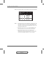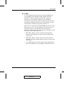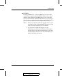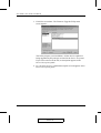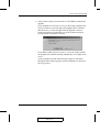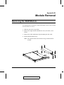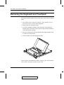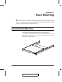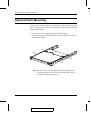
1
User Manual ACS-1208AL ACS-1216AL 2003-01-27 Warning! This is a class A product. In a domestic environment this product may cause radio interference in which case the user may be required to take adequate measures. This equipment has been tested and found to comply with the limits for a Class A digital device, pursuant to Part 15 of the FCC Rules. These limits are designed to provide reasonable protection against harmful interference when the equipment is operated in a commercial environment. This equipment generates, uses and can radiate radio frequency energy and, if not installed and used in accordance with the instruction manual, may cause harmful interference to radio communications. Operation of this equipment in a residential area is likely to cause harmful interference in which case the user will be required to correct the interference at his own expense. 2003-01-27 ACS-1208AL / ACS-1216AL User Manual Packing List The complete ACS-1208AL / ACS-1216AL package consists of: M M M M M M M 1 2 1 1 1 1 1 ACS-1208AL or ACS-1216AL KVM Switch Custom KVM Cable Sets (2L-5202P) Firmware Upgrade Cable Power Adapter with Power Cord User Manual Quick Start Guide Rack Mounting Kit Check to make sure that all the components are present and that nothing got damaged in shipping. If you encounter a problem, contact your dealer. Read this manual thoroughly and follow the installation and operation procedures carefully to prevent any damage to the unit, and/or any of the devices connected to it. ® © Copyright 2003 ATEN International Co., Ltd. Manual Part No. PAPE-0212-1AT Printed in Taiwan 01/2003 All brand names and trademarks are the registered property of their respective owners. iii 2003-01-27 ACS-1208AL / ACS-1216AL User Manual Table of Contents 1. Introduction Overview . . . . . . . . . . . . . . . . Features . . . . . . . . . . . . . . . . . Hardware Requirements . . . . . . . . Computers . . . . . . . . . . . . . Cables . . . . . . . . . . . . . . . ACS-1208AL / ACS1216AL Front View . ACS-1208AL / ACS-1216AL Rear View LCD OSD Configuration . . . . . . . . . . . . . . . . . . . . . . . . . . . . . . . . . . . . . . . . . . . . . . . . . . . . . . . . . . . . . . . . . . . . . . . . . . . . . . . . . . . . . . . . . . . . . . . . . . . . . . . . . . . . . . . . . . . . . . . . . . . . . . . . 1-1 1-3 1-4 1-4 1-4 1-6 1-8 1-10 2. Installation Before you Begin . . . . . . Single Stage Installation . . Daisy Chaining . . . . . . . Hot Plugging . . . . . . . . Port ID Numbering . . . . . Powering Off and Restarting Port Selection . . . . . . . . . . . . . . . . . . . . . . . . . . . . . . . . . . . . . . . . . . . . . . . . . . . . . . . . . . . . . . . . . . . . . . . . . . . . . . . . . . . . . . . . . . . . . . . . . . . . . . . . . . . . . . . . . . . . . . . . . . . . . . . . . . . . . . . . . . . . . . . . . . . . . 2-1 . 2-1 . 2-2 . 2-5 . 2-6 . 2-7 . 2-7 . . . . . . . . . . . . . . . . . . . . . . . . . . . . . . . . . . . . . . . . . . . . . . . . . . . . . . . . . . . . . . . . . . . . . . . . . . . . . . . . . . . . . . . . . . . . . . . . . . . . . . . . . . . . . . . . . . . . . . . . . . . . . . . . . . . . . . . . . . . . . 3-1 . 3-1 . 3-2 . 3-3 . 3-5 . 3-6 . 3-6 OSD Operation . . . . . . . . . OSD Overview . . . . . . . OSD Navigation . . . . . . OSD Main Screen Headings OSD Functions . . . . . . . . . . . . . . . . . . . . . . . . . . . . . . . . . . . . . . . . . . . . . . . . . . . . . . . . . . . . . . . . . . . . . . . . . . . . . . . . . . . . . . . . . . . . . . . . . . 4-1 . 4-1 . 4-3 . 4-3 . 4-4 3. Hotkey Operation Hotkey Port Access . . . . Invoking Hotkey Mode . Selecting the Active Port Auto Scanning . . . . . Skip Mode . . . . . . . Hotkey Beeper Control . Hotkey Summary Table 4. OSD Operation iv 2003-01-27 ACS-1208AL / ACS-1216AL User Manual 5. The Firmware Upgrade Utility Introduction . . . . . . . . . Purpose . . . . . . . . . Before You Begin . . . . Performing the Upgrade . . . Starting the Upgrade . . Upgrade Succeeded . . Upgrade Failed . . . . . Firmware Upgrade Recovery . . . . . . . . . . . . . . . . . . . . . . . . . . . . . . . . . . . . . . . . . . . . . . . . . . . . . . . . . . . . . . . . . . . . . . . . . . . . . . . . . . . . . . . . . . . . . . . . . . . . . . . . . . . . . . . . . . . . . . . . . . . . . . . . . . . . . . . . . . . . . . . . . . . . . . . . . . . . . . . . . . . . . . . . 5-1 5-1 5-2 5-3 5-3 5-6 5-6 5-7 ACS-1208AL / ACS-1216AL - Connection Tables ACS-1208AL . . . . . . . . . . . . . . . . . ACS-1216AL . . . . . . . . . . . . . . . . . OSD Factory Default Settings . . . . . . . . . . . Specifications . . . . . . . . . . . . . . . . . . . Clear Login Information . . . . . . . . . . . . . . Troubleshooting . . . . . . . . . . . . . . . . . . Limited Warranty . . . . . . . . . . . . . . . . . . . . . . . . . . . . . . . . . . . . . . . . . . . . . . . . . . . . . . . . . . . . . . . . . . . . . . . . . . . . . . . . . . . . . . . . . . . . . . . . . A-1 A-1 A-2 A-2 A-3 A-4 A-5 A-5 Appendix A, Technical Information Appendix B, Module Removal Removing the KVM Module . . . . . . . . . . . . . . . . . . . . . . B-1 Removing the Keyboard and Touchpad . . . . . . . . . . . . . . . . B-2 Appendix C, Rack Mounting Standard Rack Mounting . . . . . . . . . . . . . . . . . . . . . . . C-1 Optional Rack Mounting . . . . . . . . . . . . . . . . . . . . . . . . C-2 v 2003-01-27 ACS-1208AL / ACS-1216AL User Manual About This Manual This User Manual is provided to help you get the most from your ACS-1208AL / ACS-1216AL system. It covers all aspects of installation, configuration and operation. An overview of the information found in the manual is provided below. Overview Chapter 1, Introduction, introduces you to the ACS-1208AL / ACS-1216AL System. Its purpose, features and benefits are presented, and its front and back panel components are described. Chapter 2, Installation explains how to set up your installation — from a basic single stage hookup to a complete 32 switch daisy chained operation. Chapter 3, Hotkey Operation, details all of the concepts and procedures involved in the Hotkey operation of your ACS-1208AL / ACS-1216AL installation. Chapter 4, OSD Operation, provides a complete description of the ACS-1208AL / ACS-1216AL’s OSD (On Screen Display), and how to work with it. Chapter 5, The Firmware Upgrade Utility, explains how to use this utility to upgrade the ACS-1208AL / ACS-1216AL’s firmware with the latest available versions. An Appendix at the end of the manual provides specifications and other technical information regarding the ACS-1208AL / ACS-1216AL. vi 2003-01-27 ACS-1208AL / ACS-1216AL User Manual Conventions The following typographical conventions are used throughout this manual: M Bullet lists provide information, but not procedural steps. 1. Numbered lists represent procedures with sequential steps. An indented typeface like the one below: Key information in indicates words and characters you key in. Unless otherwise mentioned, you can use either upper or lower case. The names of the keys you should press are placed inside of square brackets, and appear just as they do on the keyboard (for example, [Alt], [Enter], [Esc]). Don’t type the brackets or anything that appears inside of them, just press the key. For example, if a procedure tells you to type: Install [Enter] You should type the word Install in either upper or lower case, then press the Enter key. If you need to hold down one key and, while you are holding it down, press another key, the keys appear in square brackets with a dash between them. For example, [Ctrl-Alt-Del] means to hold down the Ctrl and Alt keys and, while they are being held down, press the Del key and then release all the keys together. If you are asked to Choose or Select an item listed on a menu, Click it with the mouse. An alternate shortcut method is to press the appropriate accelerator key combination indicated on the menu. vii 2003-01-27 ACS-1208AL / ACS-1216AL User Manual Notes: viii 2003-01-27 Chapter 1. Introduction chapter introduces you to the ACS-1208AL / ACS-1216AL KVM Switch. Its This purpose, features and benefits are presented, and its front and back panel components are described. Overview The Master View ACS-1208AL and ACS-1216AL KVM Switches are control units that allow access to multiple computers from a single console (keyboard, mouse, and monitor). Before the development of the Master View, the only way to control multiple computer configurations from a single console was through a complex and costly network system. Now, with the Master View ACS-1208AL and ACS-1216AL, you can easily access multiple computers in a cost effective manner. A single Master View ACS-1208AL or ACS-1216AL can control up to 8 or 16 computers, respectively. As many as 31 additional Master View units can be daisy chained to each other, so that up to 512 computers can all be controlled from a single keyboard-monitor-mouse console. The Master View ACS-1208AL / ACS-1216AL offers a space-saving, streamlined approach to KVM switch technology by integrating a keyboard, LCD monitor, and touchpad in a Slideaway housing. The LCD display is built into the cover; the keyboard and touchpad are built into the base. Slide the KVM module section out; flip the cover up; and you are ready to go to work. When finished, simply flip the cover down and slide the KVM module away. For further convenience, the Slideaway housing is 1U high for easy rack mounting. The ACS-1208AL / ACS-1216AL also features high density 15 pin connectors instead of the usual 25 pin connectors. This space-saving innovation allows a full, 16 port switch to be installed in 1-1 2003-01-27 ACS-1208AL / ACS-1216AL User Manual a 1U system rack. Because of its modular design, the KVM section can be detached from the switch section. If you ever need to expand your connections, you can remove the 8 port Switch module; and replace it with a 16 port Switch module. Your ACS-1208AL / ACS-1216AL investment is protected by an included Firmware Upgrade Utility. You can stay current with the latest functionality improvements by downloading firmware update files from our website as they become available, and using the utility to quickly and conveniently perform the upgrade. Setup is fast and easy; plugging cables into their appropriate ports is all that is entailed. Because the ACS-1208AL / ACS-1216AL intercepts keyboard input directly, there is no software to configure; no need to get involved in complex installation routines; nor any need to be concerned with incompatibility problems. Access to any computer connected to the installation is easily accomplished either by entering Hotkey combinations from the keyboard, or by means of a powerful mouse driven OSD (On Screen Display) menu system. A convenient Auto Scan feature also permits automatic scanning and monitoring of the activities of all computers running on the installation one by one. There is no better way to save time and money than with a Master View ACS-1208AL / ACS-1216AL installation. By using the Master View ACS-1208AL / ACS-1216AL with its Slideaway console to manage your installation, you: (1) eliminate the expense of having to purchase a separate keyboard, monitor, and mouse for each computer; (2) save all the space those extra components would take up; (3) save the space that a keyboard, monitor, and mouse would take with a standard KVM switch; (4) save on energy costs; and (5) eliminate the inconvenience and wasted effort involved in constantly moving from one computer to another. 1-2 2003-01-27 Introduction Features w Integrated KVM Console with 15" LCD Monitor - In a 1U High Slideaway Housing For Convenient Rack Mounting w Space Saving Technology - A Single Console Controls Up To 8 (ACS-1208AL) or 16 (ACS-1216AL) Computers w Daisy Chain Up To 31 Additional Units - Control Up to 512 Computers From the Unit’s Integrated Slideaway Console w Modular Design - Console Detaches From the Switch Chassis for Easy Maintenance w Keyboard/Touchpad Module is Easily Removed for Quick Repair or Replacement - Eliminates Lengthy Down Times - No Need to Return the Switch to the Factory w No Software Required - Convenient Computer Selection via Hotkeys and Mouse Driven Intuitive On Screen Display (OSD) Menus w Auto Scan Feature for Monitoring User-Selected Computers w Hot Pluggable - Add or Remove Computers Without Having To Power Down the Switch w Daisy Chained Station Positions Auto-Sensed - No Manual DIP Switch Setting - Front Panel LED Indicates Station Position w Port Names Automatically Reconfigured When Station Sequence Changes w Two Level Password Security - Only Authorized Users View and Control the Computers - Up to Four Users Plus an Administrator with Separate Profiles For Each w Two Level Logout - Manual and Timed w PS/2 Keyboard and Mouse Emulation - Computers Boot Even When the Console Focus is Elsewhere w Superior Video Quality - Supports Resolutions of Up To 1024 x 768 w DDC Emulation of the LCD Monitor - VGA Settings of Every Connected Computer are Automatically Adjusted for Optimal Output to the LCD Monitor w Upgradable Firmware 1-3 2003-01-27 ACS-1208AL / ACS-1216AL User Manual Hardware Requirements Computers The following equipment must be installed on each computer: w A VGA, SVGA or Multisync card. Note: Since the integrated LCD monitor’s maximum resolution is 1024 x 768, make sure that the computer resolution settings do not exceed 1024 x 768. w A 6-pin mini-DIN (PS/2 style) mouse port.* w Either a 6-pin mini-DIN (PS/2 Style) keyboard port with +5V DC on pin 4 and Ground on pin 3, or a 5-pin DIN (AT Style) keyboard port with +5V DC on pin 5 and ground on pin 4.* * See the note under Cables on p. 1-5. Cables Substandard cables may damage the connected devices or degrade overall performance. For optimum signal integrity and to simplify the layout, we strongly recommend that you use the high quality CS Custom Cable sets described below: Function CS Part Number KVM Switch to KVM Switch (Daisy Chaining) 2L-1700 - 0.6 m 2L-1701 - 1.8 m KVM Switch to Computer 2L-5201P - 1.2 m 2L-5202P - 1.8 m 2L-5203P - 3.0 m 1-4 2003-01-27 Introduction 2L-1700 / 2L-1701 2L-5201P / 5202P / 5203P Note: 1. The ACS-1208AL/ACS-1216AL does not support serial mice. You cannot use Serial-to-PS/2 adapters with the cables. Attempts to do so will not work. 2. If your computer uses an AT style keyboard socket you will need to purchase a PS/2-to-AT keyboard adapter (Part No. 2A-106, or any standard keyboard adapter), in order to plug the cable into the computer’s keyboard port. 1-5 2003-01-27 ACS-1208AL / ACS-1216AL User Manual ACS-1208AL / ACS1216AL Front View 1 2 3 4 10 9 8 5 6 7 1. Handle Pull to slide the KVM module out; push to slide the module in. 2. Cover After sliding the KVM module out, flip up the cover to access the LCD monitor, keyboard and touchpad. 3. Port LEDs Port LEDs provide status information about their corresponding CPU Ports. The top row of LEDs corresponds to Ports 1 - 8; the bottom row corresponds to Ports 9 - 16. There are two LEDs for each Port. The one on the left is the On Line LED; the one on the right is the Selected Port LED: w An On Line LEDs light ORANGE to indicate that the computer attached to the corresponding port is up and running. w A Selected LEDs light GREEN to indicate that the computer attached to the corresponding port is the one that has the KVM focus. The LED is steady under normal conditions, but flashes when its port is accessed under Auto Scan Mode (see F7 SCAN, p. 4-14). 1-6 2003-01-27 Introduction Note: 1. Since the ACS-1208AL only has eight ports, only the top row of LEDs (corresponding to Ports 1 - 8) are active on that unit. On the ACS-1216AL, both rows are active. 2. When the ACS-1208AL / ACS-1216AL is first powered on, the On Line and Selected LEDs blink one after the other as the Switch performs a self-test. 4. Keyboard 5. Power LED Lights BLUE to indicate that the unit is receiving power. 6. Slide Release For convenience and to prevent inadvertent damage to the console, the ACS-1208AL / ACS-1216AL has a mechanism that locks it in the “In” position to prevent it from accidentally sliding out. In order to slide the the console out, you must first release it by moving this tab sideways. 7. Rack Mounting Brackets There are rack mounting brackets attached to each corner of the unit. They are used to secure the chassis to a system rack. Refer to Appendix C for rack mounting details. 8. Touchpad 9. LCD Display Controls The LCD On/Off Switch is located here, as well as buttons to control the position and picture settings of the LCD display. See the LCD OSD Configuration section p. 1-10, for details. 10. Reset Switch Pressing this switch in performs a system reset. This switch is recessed and must be pushed with a thin object - such as the end of a paper clip, or a ballpoint pen. 1-7 2003-01-28 ACS-1208AL / ACS-1216AL User Manual ACS-1208AL / ACS-1216AL Rear View 3 3 4 4 1 2 1 2 5 6 5 6 1. Daisy Chain Port When Daisy Chaining Units, the cable plugs in here. 2. CPU Port Section The cables that link to the computers plug in here. Note: The shape of these 15-pin connectors has been specifically modified so that only KVM cables designed to work with this switch can plug in (see the Cables section on p. 4, for details). Do NOT attempt to use ordinary 15 pin VGA connector cables to link these ports to the computers. 3. Cable Tie Slot If you want to use a cable tie to gather the cables together, you can run it through this slot to attach it to the unit. 4. Power Jack The power adapter cable plugs in here. 1-8 2003-01-27 Introduction 5. Firmware Upgrade Port The Firmware Upgrade Cable that transfers the firmware upgrade data from the administrator’s computer to the ACS-1208AL / ACS-1216AL (see p. 5-2), plugs into this RJ-11 connector. 6. Firmware Upgrade Recovery Switch During normal operation and while performing a fimware upgrade, this switch should be in the NORMAL position. See p. 5-7 for details about the use of this switch. 1-9 2003-01-27 ACS-1208AL / ACS-1216AL User Manual LCD OSD Configuration The LCD OSD allows you to set up and configure the LCD display: w To bring up the LCD OSD main menu, press the button marked Menu. w Use the ▲ and ▼ buttons to navigate and make adjustments with; after navigating to a setting choice, use the Menu button to bring up the adjustment screen. w When making adjustments, ▲ increases the value; ▼ decreases the value. w When you are satisfied with your adjustment, press Exit to return to the OSD main menu. w When all your adjustments have been made, press Exit to close the LCD OSD. An explanation of the settings is given in the table below: Auto Adjust Automatically configures all the settings for the LCD panel to what the OSD considers the optimum values Brightness Adjusts the background black level of the screen image. Contrast Adjusts the foreground white level of the screen image. Phase Adjusts the vertical size of the screen image. Clock Adjusts the horizontal size of the screen image. H-Position Positions the display area on the LCD panel horizontally (moves the display area left or right). V-Position Positions the display area on the LCD panel vertically (moves the display area up or down). Color Adjustment Adjusts the color quality of the display. You can adjust the “warmth” value, color balance, etc. The Adjust Color selection has a further submenu that lets you fine tune the RGB values. Language Selects the language that the OSD displays its menus in. Recall Resets the adjustments on all menus and submenus to their factory default settings. 1-10 2003-01-27 Chapter 2. Installation chapter explains how to connect up your installation — from a basic single This stage hookup to a complete daisy chained setup. Before you Begin 1. Make sure that power to all the devices you will be connecting up have been turned off. 2. To prevent damage to your equipment due to ground potential difference, make sure that all devices on the installation are properly grounded. Consult your dealer for technical details, if necessary. Single Stage Installation In a Single Stage installation, there are no additional switches daisy chained down from the first unit. To set up a single stage installation do the following: 1. Use KVM cable sets (as described in the Cables section on p. 1-4), to connect any available CPU Port to the Keyboard, Video and Mouse ports of the computer you are installing. Note: Ignore the Daisy Chain Port at this time. It is only used when daisy chaining additional Master View units. Daisy chaining is described in the next section. 2. Plug the power adapter cable into the Master View’s Power Jack, then plug the power adapter into an AC power source. 2-1 2003-01-27 ACS-1208AL / ACS-1216AL User Manual 3. Turn on the power to the computers. Daisy Chaining To control even more computers, up to 31 additional Master View ACS-1208A / ACS-1216A units can be daisy chained down from the First Station. Note: It would be unnecessarily wasteful and expensive to use ACS-1208AL / ACS-1216AL switches for daisy chaining since there is no point in having consoles on the chained switches. Therefore, ACS-1208A and ACS-1216A switches are used, instead. These are similar in all respects to the ACS-1208AL and ACS-1216AL, except that they come in standard housings without the built in Slideaway console. As many as 256 (ACS-1208AL) or 512 (ACS-1216AL) computers can be controlled from the unit’s integrated Slideaway console in a complete installation. Tables showing the relation between the number of computers and the number of Master View ACS-1208A / ACS-1216A units needed to control them are provided on p. A-1 in the Appendix. 2-2 2003-01-27 Installation To set up a daisy chained installation, do the following: 1. Make sure that power to all the devices you will be connecting up has been turned off. 2. Use a daisy chain cable set (described in the Cables section, p. 1-4), to connect the Chain Out port of the parent unit to the Chain In port of the child unit (First Station Out to Second Station In, Second Station Out to Third Station In, etc.). 3. Use KVM cable sets (described in the Cables section, p. 1-4), to connect any available CPU Port to the Keyboard, Video and Mouse ports of the computers you are installing. 4. Repeat the above steps for any additional Master View units you wish to add to the chain. 5. Power up the installation according to the following procedure: a) Plug in the power adapter for the First Station. Wait a few seconds for the unit to ascertain its Station ID. b) Plug in the power adapters for each Station on the installation in turn (Second Station, then Third Station, etc.). Each ACS-1208A / ACS-1216A has a LED display on its front panel to indicate its Station ID (the Station ID for the First Stage unit is 01, the ID for the Second Stage unit is 02, the ID for the Third Stage unit is 03, etc.). In each case, wait for the Station ID to be ascertained and displayed on the Station ID LED before plugging in the next Station. c) After all the Stations are up, power on the computers. 2-3 2003-01-27 ACS-1208AL / ACS-1216AL User Manual ACS-1216AL ACS-1216A ACS-1216A 2-4 2003-01-27 Installation Hot Plugging The ACS-1208AL / ACS-1216AL supports hot plugging - components can be removed and added back into the installation by unplugging their cables from the ports without the need to shut the unit down. In order for hot plugging to work properly, however, the procedures described below must be followed: Switching Station Positions: You can switch station positions by simply unplugging from the old parent and plugging into a new one. After you do, in order for the OSD menus to correspond to the change, you must reset the Station IDs in the OSD. See RESET STATION IDS, p. 4-11, for details. Note: If the computer’s Operating System does not support hot plugging, this function may not work properly. Hot Plugging CPU Ports: In order for the OSD menus to correspond to the change, you must manually reconfigure the OSD to reflect the new Port information. See the F3 SET (p. 4-6) and F4 ADM (p. 4-8), functions for details . 2-5 2003-01-27 ACS-1208AL / ACS-1216AL User Manual Port ID Numbering Each CPU port on a Master View installation is assigned a unique Port ID. The Port ID is made up of two parts: a Station Number, and a Port Number: M The Station Number - is a two digit number which reflects the switch’s position in the daisy chain sequence. Note: 1. The first station ACS-1208AL / ACS-1216AL has a Station Number of 01. The first daisy chained unit (ACS-1208A / ACS-1216A) has a Station Number of 02, etc. 2. The daisy chained ACS-1208A / ACS-1216As have front panel LEDs that display their Station IDs. M The Port Number - is a two digit number which reflects the port on the Station that the computer is connected to. M The Station Number precedes the Port Number. M Station and Port numbers from 1 - 9 are padded with a preceding zero, so they become 01 - 09. For example, a computer attached to Port 6 of Station 12 would have a Port ID of: 12-06. 2-6 2003-01-27 Installation Powering Off and Restarting If it becomes necessary to Power Off one of the ACS-1208A / ACS1216A units, unplug the power adapter cable from the rear panel. Before starting it back up you must do the following: 1. Shut down all the computers that are attached to it. Note: You must unplug the power cords of any computers that have the Keyboard Power On function. Otherwise, the switch will still receive power from the computers. 2. Wait 10 seconds, then plug the Station back in. 3. After the Station is up, Power On the computers. Note: If you have shut down more than one Station, power up the highest Station first and work your way down to the lowest one. Port Selection Port Selection is accomplished either by entering Hotkey combinations from the keyboard, or by means of the ACS-1208AL / ACS-1216AL’s OSD (On Screen Display). Hotkey Port Selection is discussed in the next chapter; OSD Operation is discussed in detail in Chapter 4. 2-7 2003-01-27 ACS-1208AL / ACS-1216AL User Manual Notes: 2-8 2003-01-27 Chapter 3. Hotkey Operation chapter details the concepts and procedures involved in the Hotkey operation This of your ACS-1208AL / ACS-1216AL installation; OSD Operation is discussed in detail in Chapter 4. Hotkey Port Access Hotkey Port Access allows you to provide KVM focus to a particular computer directly from the keyboard. The ACS-1208AL / ACS-1216AL provides the following Hotkey Port Control features: M Selecting the Active Port M Auto Scanning M Skip Mode Switching Invoking Hotkey Mode All Hotkey operations begin by invoking Hotkey Mode. Invoking Hotkey Mode takes three steps: 1. Hold down the Num Lock key; 2. Press and release the minus key; 3. Release the Num Lock key: [Num Lock] + [-]; Note: The minus key must be released within one half second, otherwise Hotkey invocation is cancelled and it has no effect. 3-1 2003-01-27 ACS-1208AL / ACS-1216AL User Manual When Hotkey Mode is active: M The Caps Lock, and Scroll Lock LEDs flash in succession to indicate so. They stop flashing and revert to normal status when you exit Hotkey Mode. M A Command Line appears on the monitor screen. The command line prompt is the word Hotkey: in yellow text on a blue background, and displays the subsequent Hotkey information that you key in. M Ordinary keyboard and mouse functions are suspended - only Hotkey compliant keystrokes and mouse clicks (described in the sections that follow), can be input. Pressing [Esc] exits Hotkey Mode. Selecting the Active Port Each CPU port is assigned a unique Port ID (see Port ID Numbering, p. 2-6). You can directly access any computer on the installation with a Hotkey combination that specifies the Port ID of the CPU Port that the computer is connected to. The steps involved are: 1. Invoke Hotkey Mode (see p. 3-1). 2. Key in the Port ID The Port ID numbers display on the Command Line as you key them in. If you make a mistake, use [Backspace] to erase the wrong number. 3. Press [Enter] After you press [Enter], the KVM focus switches to the designated computer and you automatically exit Hotkey Mode. 3-2 2003-01-27 Hotkey Operation Auto Scanning Auto Scan automatically switches among all the active CPU Ports that are accessible to the currently logged on User at regular intervals, so that he can monitor their activity automatically. (See Scan/Skip Mode of the OSD F3 SET function, p. 4-7 for information regarding accessible ports.) Setting the Scan Interval: The amount of time Auto Scan dwells on each port is set with the Scan Duration setting of the OSD F3 SET function (see p. 4-7). You can change the scan interval before activating Hotkey Auto Scanning, if you wish, with the following Hotkey combination: 1. Invoke Hotkey Mode (see p. 3-1). 2. Key in [T] [n] Where [T] is the letter T, and [n] is a number from 1-255 that represents the number of seconds the system dwells on a port before going on to the next. The letter T and the numbers display on the Command Line as you key them in. If you make a mistake, use [Backspace] to erase the wrong number. 3. Press [Enter] After you press [Enter], you automatically exit Hotkey Mode, and are ready to invoke Auto Scanning. 3-3 2003-01-27 ACS-1208AL / ACS-1216AL User Manual Invoking Auto Scan: To start Auto Scanning, key in the following Hotkey combination: 1. Invoke Hotkey Mode (see p. 3-1). 2. Press [A]. When you press A, you automatically exit Hotkey Mode; enter Auto Scan Mode; and Auto Scanning begins. M While you are in Auto Scan Mode, you can pause the scanning in order to keep the focus on a particular computer either by pressing P or with a Left Click of the mouse. During the time that Auto Scanning is paused, the Command Line displays: Auto Scan: Paused. Pausing when you want to keep the focus on a particular computer is more convenient than Exiting Auto Scan Mode because when you Resume scanning, you start from where you left off. If, on the other hand, you were to Exit Auto Scan Mode, scanning would start over from the very first computer on the installation when you restarted. To resume Auto Scanning after Pausing, press any key or Left Click. Scanning continues from where it left off. M While Auto Scan Mode is in effect, ordinary keyboard and mouse functions are suspended - only Auto Scan Mode compliant keystrokes and mouse clicks can be input. You must exit Auto Scan Mode in order to regain normal control of the console. 3. To exit Auto Scan Mode press [Esc] or [Spacebar]. Auto Scanning stops when you exit Auto Scan Mode. 3-4 2003-01-27 Hotkey Operation Skip Mode This feature allows you to switch between computers in order to monitor them manually. You can dwell on a particular port for as long or as little as you like - as opposed to Auto Scanning, which automatically switches after a fixed interval. To invoke Skip Mode, key in the following Hotkey combination: 1. Invoke Hotkey Mode (see p. 3-1). 2. Key in [Arrow] M Where [Arrow] refers to one of the Arrow keys. After you press [Arrow], you automatically exit Hotkey Mode, and enter Skip Mode where you can switch ports as follows: ← Skips from the current port to the first accessible port previous to it. (See Scan/Skip Mode, p. 4-7, for information regarding accessible ports.) → Skips from the current port to the next accessible port. ↑ Skips from the current port to the last accessible port of the previous Station. ↓ Skips from the current port to the first accessible port of the next Station. M Once you are in Skip Mode, you can keep on skipping by pressing the Arrow keys. You don’t have to use the [NumLock] + [-] combination again. M While Skip Mode is in effect, ordinary keyboard and mouse functions are suspended - only Skip Mode compliant keystrokes can be input. You must exit Skip Mode in order to regain normal control of the console. 3. To exit Skip Mode, press [Esc] or [Spacebar]. 3-5 2003-01-27 ACS-1208AL / ACS-1216AL User Manual Hotkey Beeper Control The Beeper can be Hotkey toggled On and Off (see Activate Beeper, p. 4-9). To toggle the Beeper, key in the following Hotkey combination: 1. Invoke Hotkey Mode (see p. 3-1). 2. Press [B] After you press B, the Beeper toggles On or Off. The Command Line displays Beeper On or Beeper Off for one second; then the message disappears and you automatically exit Hotkey Mode. Hotkey Summary Table [Num Lock] + [-] [Port ID] [Enter] Switches access to the computer that corresponds to that Port ID. [T] [n] [Enter] Sets the Auto Scan interval to n seconds - where n is a number from 1 - 255. [A] Invokes Auto Scan Mode. When Auto Scan Mode is in effect, [P] or Left Click pauses Auto Scanning. When Auto Scanning is paused, pressing Any Key or another Left Click resumes Auto Scanning. [←] Invokes Skip Mode and Skips from the current port to the first accessible port previous to it. [→] Invokes Skip Mode and Skips from the current port to the next accessible port. [↑] Invokes Skip Mode and Skips from the current port to the last accessible port of the previous Station. [↓] Invokes Skip Mode and Skips from the current port to the first accessible port of the next Station. [B] Toggles the Beeper On or Off. 3-6 2003-01-27 Chapter 4. OSD Operation chapter provides a complete description of the procedures involved in the OSD This (On Screen Display) operation of your ACS-1208AL / ACS-1216AL installation. OSD Operation OSD Overview The On Screen Display (OSD) is a menu driven method to handle computer control and switching operations. All procedures start from the OSD Main Screen. To pop up the Main Screen, tap the [Scroll Lock] key twice. Note: You can optionally change the Hotkey to the Ctrl key, in which case you would tap [Ctrl] twice (see OSD Hotkey, p. 4-6). With this method, the [Ctrl] keys must be on the same side (both left, or both right). The OSD incorporates a two level (Administrator / User) password system. Before the OSD Main Screen comes up, a login dialog box appears that asks you to provide your username password. If the password function has been set, you must provide a valid username and password in order to access the OSD Main Screen. If this is the first time that the OSD is being run, or if the password function has not been set, simply press [Enter]. The OSD Main Screen comes up in Administrator Mode. In this mode, you have Administrator privileges, with access to all Administrator and User functions, and can set up operations (including password authorization for the future), as you would like. 4-1 2003-01-27 ACS-1208AL / ACS-1216AL User Manual When you invoke the OSD, a screen similar to the one below appears: F1:GOTO F3:SET F2:LIST F4:ADM ADMINISTRATOR LIST:ALL SN PN QV 01 01 01 02 02 02 02 02 14 15 16 01 02 03 04 05 F5:SKP F6:BRC F7:SCAN X z F8:LOUT zz NAME ATEN INTL.CO. 1 ATEN INTL.CO. 2 ATEN INTL.CO. 3 FAX SERVER 1 FAX SERVER 2 WEB SERVER 1 WEB SERVER 2 MAIL SERVER 1 Note: 1. The diagram depicts the Administrator’s Main Screen. The User Main Screen does not show the F4 and F6 functions, since these are reserved for the Administrator and can’t be accessed by ordinary Users. 2. OSD always starts in List view, with the highlight bar at the same position it was in the last time it was closed. 3. Only the ports that have been set accessible by the Administrator for the currently logged in User are visible (see SET ACCESSIBLE PORTS, p. 4-10, for details). 4-2 2003-01-27 OSD Operation OSD Navigation w To dismiss the menu, and deactivate OSD, Click the X at the upper right corner of the OSD Window; or press [Esc]. w To Logout, Click F8 or the ZZZ symbol at the top of the Main Screen, or press [F8]. w To move up or down through the list one line at a time, Click the Up and Down Triangle symbols (▲▼) or use the Up and Down Arrow Keys. If there are more list entries than there is room for on the Main Screen, the screen will scroll. w To move up or down through the list one screen at a time, Click the Up and Down Arrow symbols (éê), or use the [Pg Up] and [Pg Dn] keys. If there are more list entries than there is room for on the Main Screen, the screen will scroll. w To activate a port, Double Click it, or move the Highlight Bar to it then press [Enter]. w After executing any action, you automatically go back to the menu one level above. OSD Main Screen Headings Heading Explanation SN-PN This column lists the Port ID numbers (Station Number - Port Number) for all the CPU ports on the installation. The simplest method to access a particular computer is move the Highlight Bar to it, then press Enter. QV If a port has selected for Quick View scanning (see Set Quick View Ports, p. 4-10), an arrowhead displays in this column to indicate so. The computers that are powered on and are On Line have a Sun symbol in this column to indicate so. NAME If a port has been given a name (see Edit Port Names, p. 4-9), its name appears in this column. 4-3 2003-01-27 ACS-1208AL / ACS-1216AL User Manual OSD Functions OSD functions are used to configure and control the OSD. For example, you can: rapidly switch to any port; scan selected ports only; limit the list you wish to view; designate a port as a Quick View Port; create or edit a port name; or make OSD setting adjustments. To access an OSD function: 1. Either Click a Function Key field at the top of the Main Screen, or press a Function Key on the keyboard. 2. In the Submenus that appear make your choice either by Double Clicking it, or moving the Highlight Bar to it, then pressing [Enter]. 3. Press [Esc] to return to the previous menu level. F1 GOTO: Clicking the F1 field or pressing [F1] activates the GOTO function. GOTO allows you to switch directly to a port either by keying in the port’s Name, or its Port ID. w To use the Name method, key in 1; key in the port’s Name; then press [Enter]. w To use the Port ID method, key in 2; key in the Port ID; then press [Enter]. Note: You can key in a partial Name or Port ID. In that case, the screen will show all the computers that the User has View rights to (see SET ACCESSIBLE PORTS, p. 4-10), that match the Name or Port ID pattern, regardless of the current List settings (see F2 LIST, p. 4-5, for details). To return to the OSD Main Screen without making a choice, press [Esc]. 4-4 2003-01-27 OSD Operation F2 LIST: This function lets you broaden or narrow the scope of which ports the OSD displays (lists) on the Main Screen. Many of the OSD functions only operate on the computers currently selected for Listing on the Main Screen with this function. The submenu choices and their meanings are given in the table below: Choice Meaning ALL Lists all of the ports on the installation. QVIEW Lists only the ports that have been selected as Quick View Ports (see SET ACCESSIBLE PORTS, p. 4-10). POWERED ON Lists only the ports that have their attached computers Powered On. QVIEW + POWERED ON Lists only the ports that have been selected as Quick View Ports (see SET QUICK VIEW PORTS, p. 4-10), and that have their attached computers Powered On. Move the Highlight Bar to the choice you want, then press [Enter]. An icon appears before the choice to indicate that it is the currently selected one. 4-5 2003-01-27 ACS-1208AL / ACS-1216AL User Manual F3 SET: This function allows the Administrator and each User to set up his own working environment. A separate profile for each is stored by the OSD and is activated according to the Username that was provided during Login. To change a setting: 1. Double Click it; or move the highlight bar to it, then press [Enter]. 2. After you select an item, a submenu with further choices appears. To make a selection, either Double Click it; or move the Highlight Bar to it, then press [Enter]. An icon appears before the selected choice to indicate which one it is. The settings are explained in the following table: Setting OSD HOTKEY Function Selects which Hotkey activates the OSD function: [Scroll Lock] [Scroll Lock] or [Ctrl] [Ctrl]. Since the Ctrl key combination may conflict with programs running on the computers, the default is the Scroll Lock combination. PORT ID DISPLAY POSITION Allows you to position where the Port ID appears on the monitor. The default is the upper left corner, but you can have it appear anywhere on the screen. Use the Mouse or the Arrow Keys plus Pg Up, Pg Dn, Home, End, and 5 (on the numeric keypad with Num Lock off), to position the Port ID display, then Click or press [Enter] to lock the position and return to the Set submenu. PORT ID DISPLAY DURATION Determines how long a Port ID displays on the monitor after a port change has taken place. The choices are: User Defined which lets you select the amount of time (from 1 - 255 sec.); and Always On - which displays the Port ID at all times. If you select User Defined, key in the number of seconds, then press [Enter]. The default is 3 Seconds. A setting of 0 (zero) disables this function. (Table continues on next page) 4-6 2003-01-27 OSD Operation (F3 SET: continued) Setting Function PORT ID DISPLAY MODE Selects how the Port ID is displayed: the Port Number alone (PORT NUMBER); the Port Name alone (PORT NAME); or the Port Number plus the Port Name (PORT NUMBER + PORT NAME). The default is PORT NUMBER + PORT NAME). SCAN DURATION Determines how long the focus dwells on each port as it cycles through the selected ports in Auto Scan Mode (see F7 SCAN, p. 4-14). Key in a value from 1 - 255 seconds, then press [Enter]. Default is 5 seconds; a setting of 0 disables the Scan function. SCAN/SKIP MODE Selects which computers will be accessed under Skip Mode (see F5 SKP, p. 4-12), and Auto Scan Mode (see F7 SCAN, p. 4-14). Choices are: ALL - All the Ports which have been set Accessible (see SET ACCESSIBLE PORTS, p. 4-10); QUICK VIEW - Only those Ports which have been set Accessible and have been selected as Quick View Ports (see SET QUICK VIEW PORTS, p. 4-10); POWERED ON - Only those Ports which have been set Accessible and are Powered On; QUICK VIEW + POWERED ON - Only those Ports which have been set Accessible and have been selected as Quick View Ports and are Powered On. The default is ALL. SCREEN BLANKER If there is no input from the console for the amount of time set with this function, the screen is blanked. Key in a value from 1 - 30 minutes, then press [Enter]. A setting of 0 disables this function. The default is 0 (disabled). HOTKEY COMMAND MODE Enables / Disables the Hotkey Command function in case a conflict with programs running on the computers occurs. 4-7 2003-01-27 ACS-1208AL / ACS-1216AL User Manual F4 ADM: F4 is an Administrator only function. It allows the Administrator to configure and control the overall operation of the OSD. To change a setting Double Click it; or use the Up and Down Arrow Keys to move the highlight bar to it then press [Enter]. After you select an item, a submenu with further choices appears. Double Click the choice you want, or move the Highlight Bar to it then press [Enter]. An icon appears before the selected choice so that you know which one it is. The settings are explained in the following table: Setting SET USERNAME AND PASSWORD Function This function is used to set Usernames and Passwords for the Administrator and Users: 1. One Administrator and four User passwords can be set. 2. After you select the Administrator field or one of the User fields, a screen that allows you to key in your username and password appears. The username and password may be up to 15 characters long, and can consist of any combination of letters and numbers (A - Z, 0 - 9). 3. For each individual, key in the Username and Password, then press [Enter]. 4. To modify or delete a previous Username and/or Password, use the backspace key to erase individual letters or numbers. SET LOGOUT TIMEOUT If there is no input from the console for the amount of time set with this function, the Operator is automatically logged out. A login is necessary before the console can be used again. This enables other Operators to gain access to the computers when the original Operator is no longer accessing them, but has forgotten to log out. To set the timeout value, key in a number from 1 - 180 minutes, then press [Enter]. If the number is 0 [zero], this function is disabled. Default is 0 (disbabled). (Table continues on next page) 4-8 2003-01-27 OSD Operation (F4 ADM: continued) Setting Function EDIT PORT NAMES To help remember which computer is attached to a particular port, every port can be given a name. This function allows the Administrator to create, modify, or delete port names. To Edit a port name: 1. Click the port you want, or use the Navigation Keys to move the highlight bar to it, then press [Enter]. 2. Key in the new Port Name, or modify/delete the old one. The maximum number of characters allowed for the Port Name is 12. Legal characters include: w All alpha characters: a - z; A - Z w All numeric characters: 0 - 9 w + - / : . and Space Case does not matter; the OSD displays the Port Name in all capitals no matter how they were keyed in. 3. When you have finished editing, press [Enter] to have the change take effect. To abort the change, press [Esc]. RESTORE DEFAULT VALUES This function is used to undo all changes and return the setup to the original factory default settings (see FACTORY DEFAULT SETTINGS, p. A-2) - except for the Names settings that were assigned to the Ports, which are saved. CLEAR THE NAME LIST This function is similar to Restore Default Values. The difference is that it also clears the Names settings along with undoing all changes and returning the setup to the original factory default settings. ACTIVATE BEEPER Choices are Y (for Yes), or N (for No). When activated, the beeper sounds whenever a Port is changed; when activating the Auto Scan function (see F7 SCAN, p. 4-14); or an invalid entry is made on an OSD menu. The default is Y (activated). (Table continues on next page) 4-9 2003-01-27 ACS-1208AL / ACS-1216AL User Manual (F4 ADM: continued) Setting SET QUICK VIEW PORTS Function This function lets the Administrator select which Ports to include as Quick View ports. w To select/deselect a port as a Quick View Port, Double Click the port you want, or use the Navigation Keys to move the highlight bar to it, then press [Enter]. w When a port has been selected as a Quick View Port, an arrowhead displays in the QV column of the LIST on the Main Screen to indicate so. When a port is deselected, the arrowhead disappears. w If one of the Quick View options is chosen for the LIST view (see F2 LIST, p. 4-5), only a Port that has been selected here will display on the List. w If one of the Quick View options is chosen for Auto Scanning (see SCAN/SKIP MODE, p. 4-7), only a Port that has been selected here will be Auto Scanned. The default is for no ports to be selected. SET ACCESSIBLE PORTS This function allows the Administrator to define User access to the computers on the installation on a Port-by-Port basis. For each User, select the target Port; then press the [Spacebar] to cycle through the choices: F (Full access), V (View Only), or blank. Repeat until all access rights have been set, then press [Enter]. The default is F for all users on all Ports. Note: A blank setting means that no access rights are granted. The Port will not show up on the User’s LIST on the Main Screen. (Table continues on next page) 4-10 2003-01-27 OSD Operation (F4 ADM: continued) Setting Function RESET STATION IDS If you change the position of one of the Stations in the daisy chain, the OSD settings will no longer correspond to the new situation. This function directs the OSD to rescan the Station positions of the entire installation and updates the OSD so that the OSD Station information corresponds to the new physical layout. Note: Only the Station Numbers get updated. Except for the Port Names, all Administrator settings (such as Set Accessible Ports, Set Quick View Ports, etc.), for all of the computers affected by the change, have to be manually redone. FIRMWARE UPGRADE In order to upgrade the ACS-1208AL / ACS-1216AL’s firmware (see Chapter 5), you must first invoke Firmware Upgrade Mode with this setting. 4-11 2003-01-27 ACS-1208AL / ACS-1216AL User Manual F5 SKP: Clicking the F5 field or pressing [F5] invokes Skip (SKP) Mode. This function enables you to easily skip backward or forward switching the console focus from the currently active computer port to the previous or next available one. w The selection of computers to be available for Skip Mode switching is made with the Scan/Skip Mode setting under the F3 SET function (see p. 4-7). w When you are in Skip Mode, press [ ← ] to switch to the previous computer in the List; press [ → ] to switch to the next computer in the List; press [ ↑ ] to switch to the last computer on the previous station in the List; press [ ↓ ] to switch to the first computer on the next station in the List. Note: When you Skip, you only Skip to the the previous or next available computer that is in the Scan/Skip Mode selection (see p. 4-7). w If a Port has been selected for Scan/Skip Mode, when the focus switches to that port a Left/Right Triangle symbol appears before its Port ID Display to indicate so. w While Skip Mode is in effect, the console will not function normally. You must exit Skip Mode in order to regain control of the console. w To exit Skip Mode, press [Spacebar] or [Esc]. 4-12 2003-01-27 OSD Operation F6 BRC: F6 is an Administrator only function. Clicking the F6 field, or pressing [F6], invokes Broadcast (BRC) Mode. When this function is in effect, commands sent from the console are broadcast to to all available computers on the installation. This function is particularly useful for operations that need to be performed on multiple computers, such as performing a system wide shutdown, installing or upgrading software, etc. BRC works in conjunction with the F2 LIST function. The LIST function (see p. 4-5), is used to broaden or narrow the focus of which Ports appear on the OSD Main Screen. When you Broadcast a command, it only goes to the Ports currently selected to be listed on the OSD Main Screen. w While BRC Mode is in effect, a Speaker symbol appears before the Port ID Display of the port that currently has the console focus. w While BRC Mode is in effect, the mouse will not function normally. You must exit BRC Mode in order to regain control of the mouse. w To exit BRC Mode, invoke the OSD (with the OSD Hotkey), then Click the F6 field, or press [F6], to turn BRC Mode off. 4-13 2003-01-27 ACS-1208AL / ACS-1216AL User Manual F7 SCAN: Clicking the F7 field or pressing [F7] invokes Auto Scan Mode. This function allows you to automatically switch among the available computers at regular intervals so that you can monitor their activity without having to take the trouble of switching manually. w The selection of computers to be included for Auto Scanning is made with the Scan/Skip Mode setting under the F3 SET function (see p. 4-7). w The amount of time that the focus stays on each Port is set with the Scan Duration setting under the F3 SET function (see p. 4-7). w As each computer is accessed, an S appears in front of the Port ID display to indicate that it is being accessed under Auto Scan Mode. w While you are in Auto Scan Mode, you can pause the scanning in order to keep the focus on a particular computer either by pressing P, or with a Left Click of the mouse. To resume scanning, press any key or Left Click, again. See Invoking Auto Scan, p. 3-4, for details. w To stop scanning and stay at a particular location, press the [Spacebar] to exit Auto Scan Mode. If the scanning stops on an empty port, or one where the computer is attached but is powered Off, the monitor screen will be blank, and the mouse and keyboard will have no effect. Simply wait - after the Scan Duration time is up, the Scan function will move on to the next port. w While Auto Scan Mode is in effect, the console will not function normally. You must exit Auto Scan Mode in order to regain control of the console. w To exit Auto Scan Mode, press the [Spacebar] or [Esc]. 4-14 2003-01-27 OSD Operation F8 LOUT: Clicking the F8 field or, or pressing [F8] logs you out of OSD control of the computers, and blanks the Console screen. This is different from simply pressing [Esc] when you are at the Main Screen to deactivate the OSD. With this function you must log in all over again to regain access to the OSD, whereas with [Esc], all you have to do to reenter the OSD is tap the OSD Hotkey. Note: 1. When you reenter the OSD after logging out, the screen stays blank except for the OSD Main Screen. You must input your password before you can continue. 2. If you reenter the OSD after logging out, and immediately use [Esc] to deactivate the OSD without having selected a port from the OSD menu, a Null Port message displays on the screen. The OSD Hotkey will bring up the Main OSD Screen. 4-15 2003-01-27 ACS-1208AL / ACS-1216AL User Manual Notes: 4-16 2003-01-27 Chapter 5. The Firmware Upgrade Utility chapter explains the use and function of the Firmware Upgrade Utility: how to get This the firmware upgrade files; and how to complete the process successfully. Introduction Purpose The purpose of the Windows-based Firmware Upgrade Utility (FWUpgrade.exe) is to provide an automated process for make upgrading the KVM switch’s firmware as smooth and painless as possible. The Utility comes as part of a Firmware Upgrade Package that is specific for each device. As new firmware revisions become available, new firmware upgrade packages are posted on our web site: http://www.aten.com.tw/basic/download.html Check the web site regularly to find the latest packages and information relating to them. 5-1 2003-01-27 ACS-1208AL / ACS-1216AL User Manual Before You Begin To prepare for the firmware upgrade, do the following: 1. From a computer that is not part of your KVM installation go to our Internet support site and choose the model name that relates to your device to get a list of available Firmware Upgrade Packages. 2. Choose the Firmware Upgrade Package you want to install (usually the most recent), and download it to your computer. 3. Use the Firmware Upgrade Cable (provided with this unit), to connect a COM port on your computer to the Firmware Upgrade Port of your device. Note: On a daisy chained installation, connect the cable to the First Station (Master) unit. The chained stations (Slaves) will receive the upgrade via the daisy chain cables. 4. Shut down all of the computers - but not the Stations - on your KVM installation. 5. From your KVM switch console, bring up the OSD (see p. 4-1) and select the F4ADM function. 6. Scroll down to FIRMWARE UPGRADE. Press [Enter], then press [Y] to invoke Firmware Upgrade Mode (see p. 4-11.) For your reference, the current firmware upgrade version displays on the screen. 5-2 2003-01-27 The Firmware Upgrade Utility Performing the Upgrade Starting the Upgrade To upgrade your firmware: 1. Run the downloaded Firmware Upgrade Package file - either by double clicking the file icon, or by opening a command line and entering the full path to it. The Firmware Upgrade Utility Welcome screen appears: 2. Read and Agree to the License Agreement (enable the I Agree radio button). 5-3 2003-01-27 ACS-1208AL / ACS-1216AL User Manual 3. Click Next to continue. The Firmware Upgrade Utility main screen appears: The Utility inspects your installation. All the devices capable of being upgraded by the package are listed in the Device List panel. If you select a device in the list, its description appears in the Device Description panel. 4. As you select devices, a detailed description of each appears in the Device Description panel. 5-4 2003-01-27 The Firmware Upgrade Utility 5. After you have made your selection(s), Click Next to perform the upgrade. If you enabled Check Firmware Version, the Utility compares the device’s firmware level with that of the upgrade files. If it finds that the device’s version is higher than the upgrade version, it brings up a dialog box informing you of the situation and gives you the option to Continue or Cancel. If you didn’t enable Check Firmware Version, the Utility installs the upgrade files without checking whether they are a higher level, or not. As the Upgrade proceeds status messages appear in the Status Messages panel, and the progress toward completion is shown on the Progress bar. 5-5 2003-01-27 ACS-1208AL / ACS-1216AL User Manual Upgrade Succeeded After the upgrade has completed, a screen appears to inform you that the procedure was successful: Click Finish to close the Firmware Upgrade Utility. Upgrade Failed If the upgrade failed to complete successfully a dialog box appears asking if you want to retry. Click Yes to retry. If you Click No, the Upgrade Failed screen appears: Click Cancel to close the Firmware Upgrade Utility. See the next section, Firmware Upgrade Recovery, for how to proceed. 5-6 2003-01-27 The Firmware Upgrade Utility Firmware Upgrade Recovery There are basically three conditions that call for firmware upgrade recovery: M When you invoke Firmware Upgrade Mode (see p. 5-2), but decide not to proceed with the upgrade. M When the Mainboard firmware upgrade fails. M When the I/O firmware upgrade fails. To perform a firmware upgrade recovery, do the following: 1. Slide the Firmware Upgrade Recovery Switch (see p. 1-9) to the Recover position. 2. Power off and restart the the switch according to the instructions given in the Powering Off and Restarting section (p. 2-7). 3. Slide the Firmware Upgrade Recovery Switch back to the Normal position. 4. Repeat Step 2. Note: If one of the slave units fails to upgrade successfully, unchain it from the installation and perform the recovery and upgrade operation independently. After it has been succussfully upgraded, plug it back into the chain 5-7 2003-01-27 ACS-1208AL / ACS-1216AL User Manual Notes: 5-8 2003-01-27 Appendix A. Technical Information appendix provides specifications and other technical information regarding the This ACS-1208AL / ACS-1216AL. ACS-1208AL / ACS-1216AL - Connection Tables The following tables indicate the relationship between the number of Master View units and the number of computers that they control: ACS-1208AL MVs Computers MVs Computers MVs Computers MVs Computers 1 1-8 9 65 - 72 17 129 - 136 25 193 - 200 2 9 - 16 10 73 - 80 18 137 - 144 26 201- 208 3 17 - 24 11 81 - 88 19 145 - 152 27 209 - 216 4 25 - 32 12 89 - 96 20 153 - 160 28 217 - 224 5 33 - 40 13 97 - 104 21 161 - 168 29 225 - 232 6 41 - 48 14 105 - 112 22 169 - 176 30 233 - 240 7 49- 56 15 113 - 120 23 177- 184 31 241 - 248 8 57 - 64 16 121 - 128 24 185 - 192 32 249 - 256 A-1 2003-01-27 ACS-1208AL / ACS-1216AL User Manual ACS-1216AL MVs Computers MVs Computers MVs Computers MVs Computers 1 1 - 16 9 129 - 144 17 257 - 272 25 385 - 400 2 17 - 32 10 145 - 160 18 273 - 288 26 401 - 416 3 33 - 48 11 161 - 176 19 289 - 304 27 417 - 432 4 49 - 64 12 177 - 192 20 305 - 320 28 433 - 448 5 65 - 80 13 193 - 208 21 321 - 336 29 449 - 464 6 81 - 96 14 209 - 224 22 337 - 352 30 465 - 480 7 97- 112 15 225 - 240 23 353 - 368 31 481 - 496 8 113 - 128 16 241 - 256 24 369 - 384 32 497 - 512 OSD Factory Default Settings The factory default settings are as follows: Setting Default OSD Hotkey [Scroll Lock] [Scroll Lock] Port ID Display Position Upper Left Corner Port ID Display Duration 3 Seconds Port ID Display Mode The Port Number plus the Port Name Scan Duration 5 Seconds Scan/Skip Mode All Screen Blanker 0 (Disabled) Logout Timeout 0 (Disabled) Beeper Y (Activated) Accessible Ports F (Full) For all Users on all Ports A-2 2003-01-27 Technical Information Specifications Function Computer Direct Connections Max Port Selection LEDs Connectors ACS-1208AL ACS-1216AL 8 16 256 (via Daisy Chain) 512 (via Daisy Chain) OSD (On Screen Display); Hotkeys On Line 8 (Orange) 16 (Orange) Selected 8 (Green) 16 (Green) Power 1 (Blue) Station ID 2 x 7 Segments CPU Ports 8 x SPDB-15 F Daisy Chain 1 x DB-25 M FW Upgr. 1 x RJ-11 Switches 16 x SPDB-15 F 1 x Slide (FW Upgrade Recovery) Scan Interval (OSD Select) User Specified: 1 - 255 secs. Emulation Keyboard PS/2 Mouse PS/2 Video 1024 x 768; DDC2 Power Consumption 120V 60Hz 24W / 230V 50Hz 24W Operating Temperature 0 - 50o C Storage Temperature -20 - 60o C Humidity 0 - 80% RH Housing Metal Weight 13kg Dimensions (L x W x H) 48.3 x 60 x 4.5 cm (19" / 1U) 13.5kg A-3 2003-01-27 ACS-1208AL / ACS-1216AL User Manual Clear Login Information If you are unable to perform an Administrator login (because the Username and Password information has become corrupted, or you have forgotten it, for example), you can clear the login information with the following procedure: 1. Power off the switch and remove the top cover of the Switch module case. 2. Short the jumper labeled Default Password at the right front of the switch’s main board. 3. Power on the switch. When you power the switch on, the following message appears on the LCD display: USERNAME AND PASSWORD INFORMATION HAS BEEN CLEARED. PLEASE POWER OFF THE SWITCH, REMOVE THE JUMPER, CLOSE THE CASE, THEN RESTART. 4. After you start back up, the OSD login function acts exactly the way it did the first time the switch was run (see p. 4-2) and you can reset passwords for the Administrators and Users. A-4 2003-01-27 Technical Information Troubleshooting Symptom Possible Cause Erratic behavior. Unit not receiving enough power. Action Check that the Power Adapter that was supplied with the unit is plugged in and functioning properly. Limited Warranty IN NO EVENT SHALL THE DIRECT VENDOR’S LIABILITY EXCEED THE PRICE PAID FOR THE PRODUCT FROM THE DIRECT, INDIRECT, SPECIAL, INCIDENTAL OR CONSEQUENTIAL DAMAGES RESULTING FROM THE USE OF THE PRODUCT, DISK OR ITS DOCUMENTATION. The direct vendor makes no warranty or representation, expressed, implied, or statutory with respect to the contents or use of this documentation, and specially disclaims its quality, performance, merchantability, or fitness for any particular purpose. The direct vendor also reserves the right to revise or update the device or documentation without obligation to notify any individual or entity of such revisions, or update. For further inquires please contact your direct vendor. A-5 2003-01-27 ACS-1208AL / ACS-1216AL User Manual Notes: A-6 2003-01-27 Appendix B. Module Removal Removing the KVM Module For maintenance convenience, the KVM module can be removed from the unit chassis. To do so: 1. Slide the unit to the out position. 2. Remove the eight module attachment screws (four above; four below). 3. Remove the cable attachment clip and unplug the data cable. 4. Pull the KVM module away. Note: The slider brackets and extender arm go with the KVM module. B-1 2003-08-19 ACS-1208AL / ACS-1216AL User Manual Removing the Keyboard and Touchpad The keyboard and touchpad can be easily removed for repair or replacement: 1. Turn off the power to the ACS-1208AL / ACS-1216AL (it isn’t necessary to power off any other equipment). 2. Remove the two attaching screws. 3. Locate the opening toward the front and center of the the unit’s bottom panel. The bottom of the keyboard and touchpad module is visible through the opening. 4. Push up on the bottom of the keyboard and touchpad module until it releases from the chassis. 5. Lift the module clear and unplug the cables. After you have reinstalled the module, power up the ACS-1208AL / ACS-1216AL and you are ready to go to work. B-2 2003-08-19 Appendix C. Rack Mounting he ACS-1208AL / ACS-1216AL can be mounted in a 1U system rack. For Tconvenience and flexibility, a rack mounting kit that allows several mounting options is provided with your ACS-1208AL / ACS-1216AL package. The various options are explained in the sections that follow. Standard Rack Mounting The standard rack mounting brackets that come attached to the ACS-1208AL / ACS-1216AL allow the unit to be installed in standard 1U racks. If the unit can fit into your rack “as is,” simply slide it into the rack and screw it securely in place. C-1 2003-10-07 ACS-1208AL / ACS-1216AL User Manual Optional Rack Mounting If there is not enough clearance for the unit to slide into the rack when the rear flanges face outward, the problem can be resolved with the following procedure: 1. Unscrew the rear mounting brackets from the chassis. 2. Turn the brackets so that the flanges face inward; then screw them back into the chassis. Note: Be sure to leave a 13mm gap between the flange and the rear of the chassis in order to have enough room to screw the tab to the flange (see step 4). C-2 2003-10-07 Rack Mounting 3. Slide the unit into the rack. 4. Screw the metal tabs to the rear flanges. 5. Secure the unit to the rack with the front flanges and rear tabs. C-3 2003-10-07 ACS-1208AL / ACS-1216AL User Manual Notes: C-4 2003-10-07 Index A ACS-1208AL Front View. . . . . . . . . . . . . . . . . . . . . . 1-6 Rear View . . . . . . . . . . . . . . . . . . . . . . 1-8 ACS-1208L Computer Connection Table. . . . . . . . A-1 ACS-1216AL Front View. . . . . . . . . . . . . . . . . . . . . . 1-6 Rear View . . . . . . . . . . . . . . . . . . . . . . 1-8 ACS-1216L Computer Connection Table. . . . . . . . A-2 Activate Beeper. . . . . . . . . . . . . . . . . . . . 4-9 ADM . . . . . . . . . . . . . . . . . . . . . . . . . . . . 4-8 Administrator functions . . . . . . . . . . . . . . 4-8 Auto Scanning. . . . . . . . . . . . . . . . . 3-3, 4-14 Invoking Auto Scan. . . . . . . . . . . . . . . 3-4 Pausing Auto Scan . . . . . . . . . . . . . . . 3-4 Scan Duration . . . . . . . . . . . . . . . . . . . 4-7 Setting the Scan Interval. . . . . . . . . . . 3-3 Stopping . . . . . . . . . . . . . . . . . . . . . . . 3-4 B Beeper Activate . . . . . . . . . . . . . . . . . . . . . . . . 4-9 Hotkey Control . . . . . . . . . . . . . . . . . . 3-6 BRC . . . . . . . . . . . . . . . . . . . . . . . . . . . 4-13 Broadcast Mode . . . . . . . . . . . . . . . . . . 4-13 C Clear Login Information. . . . . . . . . . . . . . Clear the Name List . . . . . . . . . . . . . . . . Computer Connection Tables . . . . . . . . . Console unlocking. . . . . . . . . . . . . . . . . . . . . . . A-4 4-9 A-1 1-7 E-F Edit Port Names . . . . . . . . . . . . . . . . . . . 4-9 F1 GOTO . . . . . . . . . . . . . . . . . . . . . . . . . 4-4 F2 LIST . . . . . . . . . . . . . . . . . . . . . . . . . . 4-5 F3 SET. . . . . . . . . . . . . . . . . . . . . . . . . . . 4-6 F4 ADM . . . . . . . . . . . . . . . . . . . . . . . . . . 4-8 F5 SKP. . . . . . . . . . . . . . . . . . . . . . . . . . 4-12 F6 BRC . . . . . . . . . . . . . . . . . . . . . . . . . 4-13 F7 SCAN . . . . . . . . . . . . . . . . . . . . . . . . 4-14 F8 LOUT . . . . . . . . . . . . . . . . . . . . . . . . 4-15 Factory Default Settings. . . . . . . . . . . . . A-2 Firmware upgrade . . . . . . . . . . . . . . . . . . 5-1 cable . . . . . . . . . . . . . . . . . . . . . . . . . . 5-2 port. . . . . . . . . . . . . . . . . . . . . . . . 1-9, 5-2 recovery . . . . . . . . . . . . . . . . . . . . . . . . 5-7 recovery switch . . . . . . . . . . . . . . . . . . 1-9 G-H GOTO . . . . . . . . . . . . . . . . . . . . . . . . . . . Hardware Requirements Cables . . . . . . . . . . . . . . . . . . . . . . . . . Computer . . . . . . . . . . . . . . . . . . . . . . . Hot Plugging . . . . . . . . . . . . . . . . . . . . . . CPU Ports . . . . . . . . . . . . . . . . . . . . . . Hotkey Auto scanning . . . . . . . . . . . . . . . . . . . Beeper Control. . . . . . . . . . . . . . . . . . . Command Mode . . . . . . . . . . . . . . . . . Invoking Hotkey Mode . . . . . . . . . . . . . OSD . . . . . . . . . . . . . . . . . . . . . . . . . . . Selecting the Active Port . . . . . . . . . . . Skip mode . . . . . . . . . . . . . . . . . . . . . . Summary Table . . . . . . . . . . . . . . . . . . 4-4 1-4 1-4 2-5 2-5 3-3 3-6 4-7 3-1 4-6 3-2 3-5 3-6 I Installation Daisy Chaining. . . . . . . . . . . . . . . . . . . 2-2 Single Stage . . . . . . . . . . . . . . . . . . . . 2-1 Invoking Hotkey Mode . . . . . . . . . . . . . . . 3-1 I-i 2003-10-07 ACS-1208AL / ACS-1216AL User Guide K Keyboard and Touchpad Removal . . . . B-2 KVM Module removal. . . . . . . . . . . . . . . B-1 L LCD Display Controls. . . . . . . . . . . . . . . . . . 1-7 OSD configuration . . . . . . . . . . . . . . . 1-10 LIST . . . . . . . . . . . . . . . . . . . . . . . . . . . . . 4-5 Logout . . . . . . . . . . . . . . . . . . . . . . . . . . 4-15 Logout Timeout . . . . . . . . . . . . . . . . . . . . 4-8 LOUT . . . . . . . . . . . . . . . . . . . . . . . . . . . 4-15 O OSD Factory Default Settings. . . . . . . . . . . A-2 Functions . . . . . . . . . . . . . . . . . . . . . . . 4-4 Hotkey . . . . . . . . . . . . . . . . . . . . . 4-1, 4-6 Logout . . . . . . . . . . . . . . . . . . . . . . . . 4-15 Main Screen. . . . . . . . . . . . . . . . 4-1 - 4-2 Main Screen Headings. . . . . . . . . . . . . 4-3 Navigation . . . . . . . . . . . . . . . . . . . . . . 4-3 Overview . . . . . . . . . . . . . . . . . . . . . . . 4-1 Password . . . . . . . . . . . . . . . . . . . . . . . 4-1 P Password . . . . . . . . . . . . . . . . . . . . . 4-1, 4-8 Pause . . . . . . . . . . . . . . . . . . . . . . . . . . . 4-14 Port ID Display Duration. . . . . . . . . . . . . . . . . . 4-6 Display Mode . . . . . . . . . . . . . . . . . . . . 4-7 Display Position . . . . . . . . . . . . . . . . . . 4-6 Numbering . . . . . . . . . . . . . . . . . . . . . . 2-6 Port Names . . . . . . . . . . . . . . . . . . . . . . . 4-9 Port Selection. . . . . . . . . . . . . . . . . . . . . . 2-7 Powering Off and Restarting . . . . . . . . . . 2-7 Q-R Quick View Ports . . . . . . . . . . . . . . . . . . 4-10 Rack mounting . . . . . . . . . . . . . . . . C-1, C-3 Optional. . . . . . . . . . . . . . . . . . . . . . . . C-2 Standard . . . . . . . . . . . . . . . . . . . . . . . C-1 Recovery switch . . . . . . . . . . . . . . . . . . . 1-9 Removing the Keyboard and Touchpad . B-2 Removing the KVM Module . . . . . . . . . . B-1 Reset Station IDs . . . . . . . . . . . . . . . . . 4-11 Restore Default Values . . . . . . . . . . . . . . 4-9 S SCAN . . . . . . . . . . . . . . . . . . . . . . . . . . 4-14 Scan Duration . . . . . . . . . . . . . . . . . . . . . 4-7 SCAN/SKIPMODE . . . . . . . . . . . . . . . . . 4-7 Screen Blanker . . . . . . . . . . . . . . . . . . . . 4-7 Selecting the Active Port . . . . . . . . . . . . . 3-2 SET . . . . . . . . . . . . . . . . . . . . . . . . . . . . . 4-6 Accessible Ports . . . . . . . . . . . . . . . . 4-10 Logout Timeout . . . . . . . . . . . . . . . . . . 4-8 Password . . . . . . . . . . . . . . . . . . . . . . 4-8 Quick View Ports. . . . . . . . . . . . . . . . 4-10 USERNAME . . . . . . . . . . . . . . . . . . . . 4-8 Setting the Auto Scan Interval . . . . . . . . 3-3 Skip Mode . . . . . . . . . . . . . . . . 3-5, 4-7, 4-12 SKP. . . . . . . . . . . . . . . . . . . . . . . . . . . . 4-12 Specifications . . . . . . . . . . . . . . . . . . . . . A-3 Station IDs . . . . . . . . . . . . . . . . . . . . . . . 2-3 Reset. . . . . . . . . . . . . . . . . . . . . . . . . 4-11 Station Positions Switching. . . . . . . . . . . . . . . . . . . . . . . 2-5 Switching Station Positions . . . . . . . . . . . 2-5 T Timeout . . . . . . . . . . . . . . . . . . . . . . . . . . 4-8 Troubleshooting . . . . . . . . . . . . . . . . . . . A-5 U Unlocking the console . . . . . . . . . . . . . . . 1-7 Upgrading the firmware. . . . . . . . . . . . . . 5-1 Username . . . . . . . . . . . . . . . . . . . . . . . . 4-8 I - ii 2003-10-07