1
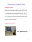
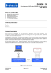
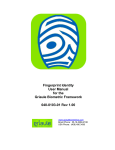
Biometric access system
EGO UBR MODULE
Installers manual
-1-
Table of contents
Safety information................................................................................................................................... 2
Precautions .............................................................................................................................................. 2
Features ................................................................................................................................................... 3
Definition of terms .................................................................................................................................. 3
Basic operation and use........................................................................................................................... 4
EGO UBR Module Overview ................................................................................................................. 6
Installation and connection...................................................................................................................... 8
Mechanical Drawings............................................................................................................................ 11
Troubleshooting .................................................................................................................................... 13
Servicing................................................................................................................................................ 14
Appendix 1 - Abbreviations .................................................................................................................. 15
Safety information
If the module suffers any kind of damage
• Turn off the power and unplug the unit’s power supply from the wall outlet immediately if
the module begins to make any unusual noises or gives off smoke or an unusual smell.
Then call EGO Secure Systems Ltd for service.
Moisture and liquid entry
• To prevent the risk of electric shock or damage to the internal electronics of the module
switch off the module and contact EGO Secure Systems Ltd for service.
Foreign object entry
• Never insert or drop any metallic or inflammable objects into any of the openings on this
module, as this may cause fire, electric shock or electrical failure.
Fire prevention
• To prevent fire, never place any type of candle or naked flame on or near the UBR
module.
Precautions
Excessive shock
• Due to the sensitive nature of biometric devices they must always be handled with care.
Excessive force or sharp knocks may damage the precision parts inside the unit
resulting in poor quality of operation.
Servicing
• To reduce risk of electric shock, do not attempt to remove the protective covers or
panels that house the module. There are no user serviceable parts within the module. If
service is required, contact EGO Secure Systems Ltd.
-2-
Features
Finger vein biometric authentication
•
•
•
•
•
•
Identification based on internal finger vein patterns
Very high level of authentication
Module hold up to 1000 templates
Suitable for the visually impaired
Ethernet connection for remote control by as ‘Intelligent’ server
Internal automated control (stand-alone) modes
Definition of terms
Biometric
Biometric refers to the process of uniquely identifying an individual through the measurement
of some aspect of their anatomy. In the case of the EGO UBR Module, it is the measurement
of the unique vein patterns inside a person’s finger that are used to identify an individual.
Template
A Template is a unique set of numbers representing the pattern of veins in a person finger.
The EGO Module can create Templates using the registration process. Please note that the
EGO UBR Module allows each user to have up to twenty stored templates. The maximum
number of templates that the EGO UBR Module can hold is 1000.
Registration
Registration is the process of the scanning of a user’s finger to obtain a biometric template.
Authentication
Authentication is the process in which the user’s finger (placed on the scanner) is compared to
one or more biometric templates. The EGO UBR Module supports 2 forms of Authentication;
authentication against the biometric templates stored within the EGO UBR Module’s internal
template database or authentication against one or more (up to 20) external templates.
Intelligent Server
The Intelligent server is a machine which exists on the same network as the EGO UBR Module
and issues commands to the EGO UBR Module using the network.
Time and attendance logging
Time and attendance logging is the recording of users and the times in which they enter and
exit the controlled door.
-3-
Secure and un-secure sides of a door
The un-secure side of a door is the side open to the public or anyone that is not registered.
The secured side is the side of the door in which the EGO UBR Module is designed to protect
or restrict access.
Identify Mode
The Identity Mode is a special function used to indentify a module connected to the Ethernet. It
has nothing to do with indentifying, verifying or authenticating a user. In ‘Identify Mode’ the
specific EGO module selected in the software is commanded to flash the Multipurpose
Indicator Light in an unusual colour sequence and to beep the sounder approximately every 9
seconds. This enables an installer to verify which NetBios name relates to which physical
module.
Basic operation and use
An extract from the Hitachi VeinID Website
Based on the unique patterns of veins, vascular pattern recognition (VPR), or vein pattern
recognition, provides the ease of use of hand geometry with much improved accuracy, smaller
readers and a much more hygienic approach. It uses near-infrared light generated from a bank
of Light Emitting Diodes projected through an individual’s skin to enable a high-contrast
matching of vein patterns (e.g., vein branching points, vein thickness, and branching angles).
VPR systems scan the de-oxygenated veins, extract key pattern features via contactless, nearinfrared optical sensor systems, digitize the extracted pattern recognition, and then match the
transaction templates to the respective pre-established enrollment template. By measuring the
veins under the skin, it is very difficult for unauthorized persons to observe or capture this
pattern, rendering VPR a highly secure method of identity verification.
Since 1997 Hitachi has been developing an original biometric, finger vein authentication
technology, which uses the finger vein pattern obtained from passing light through a finger as a
key. Its first commercial systems were deployed in 2004.
-4-
As illustrated in the adjacent figure, near-infrared light generated by a bank of light emitting
diodes penetrates the body tissue; it is reflected in the hemoglobin in the blood. A CCD
camera (which uses a small, rectangular piece of silicon to receive incoming light) captures the
image of the vein pattern through this reflected light. Image processing constructs a finger vein
pattern from the camera image. This pattern is compressed and digitized so that it can be
registered as a template for biometric authentication. Within a split second, the FV system
filters the digitized image, produces a template or digitized image that it compares to the stored
template of the user, and determines whether there is a match, using pattern-matching
techniques. Variations in environmental temperature or a person’s blood pressure can
sometimes cause fluctuations in the width and brightness of the blood vessels. The Hitachi
finger vein system pinpoints the position of the center of each blood vessel so that those vein
fluctuations do not affect the matching procedure.
For repeatable and good quality registration and authentication the positioning of the finger in
the biometric scanner is very important. Figure 1 shows the first finger in the biometric scanner
with the tip of the finger in to top guide and the base of the finger fitted into the bottom guide.
The finger should be held straight and still for the period of the registration or authentication
process (this may be up to six seconds). The finger should not be tensioned too much during
registration as this may be difficult to replicate during subsequent authentications.
Figure 1 Correct positioning of the finger
The EGO UBR Module has been designed so that any finger may be used for authentication
and registration. Some users may find it more comfortable to use the middle finger as shown in
figure 2.
-5-
Note that up to 20 templates may be stored in the EGO UBR Module associated with a single
user. This is useful in that a slight rotation of the finger between registrations (The finger must
be held still for the period of the registration) will speed up the authentication process. The
down side to this is a reduction in the number of different users that may be stored in the EGO
UBR Module due to the 1,000 template limit.
Figure 2 Use of middle finger for registration and authentication
A way around the 1,000 user limit (1 template per user) is to preselect the templates using a
card or pin number and then download only those templates require for authentication.
Alternatively using an EGO UBR Module with smart card reader fitted internally a template
may be read from the card and a match made using that template.
EGO UBR Module Overview
The EGO UBR Module (with the biometric sensor fitted) is mounted on the un-secured side of
the door and is designed to permit users entry through the door via a biometric finger match. If
a finger match is successful the door will unlock for a programmable period of time allowing
access.
-6-
Multipurpose indicator
light
Biometric scanner
indicator light
Biometric scanner
There are 2 distinct feedback light emitting diodes on the EGO UBR Module; the Multipurpose
Indicator Light and the Biometric Scanner Indicator Light mounted on the HOTS VeinID
module itself. The Biometric Scanner Indicator light is almost exclusively controlled by the
HOTS VeinID module; however there is a command which can be issued by an Intelligent
Server to cause the Biometric Scanner Indicator light to glow green.
The Multipurpose indicator light is under the control of the EGO Module processor and may be
commanded by an Intelligent Server to show various colours, or controlled using the ‘Green
LED’ and ‘Red LED’ connections (Stand Alone mode only). This Multipurpose Indicator Light
may also be controlled by a door controller and connections are provided.
The information displayed by both the Multipurpose Indicator Light and the Biometric Scanner
Indicator Light is detailed below: -
Multipurpose Indicator Light
Glowing Green
External software has signalled that all is correct (and for example the door has been
unlocked).
Glowing Red
External software has rejected identification (and for example the door has stayed
locked).
Cycling through primary colours
The EGO Module is in Identify mode (buzzer will intermittently sound as well)
-7-
Glowing Yellow
The EGO Module is in resetting (booting or forced reset)
Blue flash (every nine seconds)
The EGO Module is in stand-bye mode waiting a network connection.
Note that is usual for the EGO Module feedback LED to be turned off while the Hitachi VeinID
module LED is providing feedback to minimise confusion in the user.
Biometric Scanner Indicator Light
Glowing green
The Biometric Scanner’s start-up procedure has been completed. The light should
automatically turn off after a few seconds. Note that even when the Biometric Scanner
indicates that it has completed its start-up procedure, the EGO UBR Module may still
have additional tasks to perform before the entire start-up procedure is complete.
There is also a command which allows an intelligent server to cause the light to glow
green.
Flashing blue
Finger vein registration or authentication is in progress.
Glowing blue
Finger vein registration or verification has been successfully completed.
Flashing red
Finger vein registration or verification has failed.
Glowing red
Hitachi VeinID error status; an error in the operation of the device has occurred or the
unit has detected inadequate light levels for operation.
Installation and connection
Operating conditions
•
•
•
•
•
•
•
•
•
•
•
802.3af - 2003 compliant Power over Internet 13 watt supply
Auxiliary 12V dc +/- 8% input at 1 Amp supplied by Regulated 12 volt supply at 1.25
amps
Operating and Storage Temperature -10°C to +75°C
15% to 85% Relative Humidity (Non-Condensing)
-10°C to 60°C (ambient temperature)
Hitachi VeinID Module operating 5°C to 45°C
Fully CE approved and tested
RoHS Compliant
May be used outdoors with addition of an EGO Weather Cowl
No direct sunlight
Limited light sources to 2,300 lux or less
Recommended light:
Fluorescent lamp (Light intensity centred around a wavelength of 500~600nm)
Recommended colour:
-8-
White, daylight white, daylight colour
Cable lengths
The EGO Biometric Module, as with all EGO Modules, has been designed to use Cat5E
screened cable with a screened RJ45 connector providing an earth to the module. If a fully
screened RJ45 connector is not used and to comply with the CE specification there is a 3mm
screw earth point provided on the metal chassis of the EGO module and this should be
connected to a good earth point.
The lengths of cables that may be used to connect the EGO Module to the rest of the system
are limited by the use of the EGO Module. When the EGO Module is powered using the Power
over Ethernet function then the cable length between the EGO Module and the Power over
Ethernet injector is a maximum of 90 metres.
When a legacy mode is used and the power is applied via the Wiegand cables then the
maximum cable length can be as little as 25 metres.
DC supply
Note that using an external DC supply the voltage applied to the EGO Biometric Sensor
module should be +12 volts DC +/-8%. This is for the Hitachi UBR module. The module will
draw approximately 600mA (after inrush current). It is recommended that a 12 volt regulated
power supply is used. Care must be taken if the power cables are long as there may be
significant voltage drop however the voltage applied to the EGO Biometric Sensor Module
must never exceed 12.9volts DC or drop below 11.1volts.
Out door use
While the EGO Module is designed to be weather proof to IP67 the Hitachi VeinID module is
not. Also the Hitachi VeinID module will not work in bright daylight. To overcome these
limitations RFID Systems PLC can supply a weatherproof hood that allows external use in all
but the most extreme conditions.
NB the Hitachi VeinID Module performs a self-diagnosis soon after power is applied. If the
lighting environment is inappropriate, the Hitachi VeinID feedback LED will glow red.
Recommended light: Fluorescent lamp (Light intensity centred on a wavelength of
500~600nm) Recommended colour: White, daylight white, daylight colour
Power over Ethernet
The EGO Module (like most EGO modules) supports both Mode A and Mode B Power over
Ethernet to IEEE std.802.3af-2003. This means that any POE injector, both mid span and end
span may be used to power the EGO module.
POE Description: 36v to 57v (nominally 48v), applied to the Ethernet twisted pairs pins 1-2 and
3-6 (mode A) or to pins 4-5 and 7-8 (Mode B), is tapped off from the Ethernet magnetic’s and
applied via two bridge rectifiers to the POE conditioning circuits. These POE conditioning
circuits apply the correct loads, in sequence, to set the correct ‘power class’ (in this case 13
watts) for the EGO Biometric Sensor Module. Further circuits within the EGO module then
condition the DC supplies required for the Hitachi VeinID module and the rest of the circuits.
-9-
Note that the End Span POE source will supply many Ethernet POE units and is often called a
POE Switch, as the functions of an Ethernet Switch and POE source are combined into one
unit; while a Mid Span unit is called an Ethernet Injector, as it usually only supplies one unit.
Connections
Signal Ground
Wiegand Data 0
JP2
Wiegand Data 1
Ethernet
Cable
1
Green LED
Red LED
JP1
1
Buzzer
RJ45
Ethernet
Connector
+'ve DC Supply
JP6
+'ve DC Supply
1
-'ve DC Supply
LED A LEDB
Yellow Red
Note that the Signal ground connection and the –‘ve DC Supply connection are linked together
inside the EGO Module. Also on JP6 the two +’ve DC Supply connections are linked inside the
EGO Module.
- 10 -
To illuminate the Red or Green Multipurpose Indicator Light or to sound the Buzzer (in standalone mode only) the relevant pin on JP1 should be pulled to ground, with for example an open
collector transistor. These 3 pins are pulled up to 3v3 DC inside the EGO Biometric Sensor
module via a 4k7 resistors.
The two LEDs labelled as LED A and LED B on the connection diagram are configured to
automatically display link status (Yellow) and RX/TX activity (Red) of the EGO UBR Module
Ethernet port.
Legacy Support
The EGO UBR Module can support Legacy door controllers and other devices by using the
Wiegand data output option. The Wiegand bus consists of two data lines and a signal return
line. The data lines sit at a positive voltage, in the case of the EGO Module this is + 5volts DC
with respect to the signal ground pin. Data is transmitted by setting either the 0 line or the 1
line to ground for a short period. There is no valid condition (with power applied to the unit)
where both the Data 0 line and the Data 1 line can be at zero volts at the same time.
Note that the Wiegand Data 0 and Data 1 lines will not supply a significant amount of current
and should not be used as power sources for other circuitry.
The Wiegand bus may be formatted for almost any data length and information content but will
be shipped with the 26 bit format as shown below.
Wiegand 26 bit format as follows: PSSSSSSSSNNNNNNNNNNNNNNNNP
BIT 1 2
9 10
25 26
where
BIT 1 is an even parity for the following 12 bits. The sum of bits 1-13 is even.
BITS 2-9 are the SITE CODE.
BITS 10-25 are the USER CODE.
BIT 26 is an odd parity over the previous 12 bits. The sum of bits 14-26 is odd.
Mechanical Drawings
This section shows the mechanical drawings for mounting an EGO Module onto a wall. The
Drawing below gives dimensions of the 4 fixing holes (note that the drawing is 1 to 1 scale and
may be used as a drilling template). There are 5 areas in the EGO wall mounting plate that are
- 11 -
designed to allow cable access; 1 central gland molding in the centre of the base and 4 areas
around the side walls. There are corresponding areas on the EGO Cover.
The Wall plate is mounted on the wall first and the cabling made ready. The connections are
then made to the EGO module. The EGO Module is fitted to the wall plate at the top first and
- 12 -
then a single screw is used to fix it to the bottom. The screw hole is covered by the EGO Label
supplied with the module once all the connections have been proved.
Troubleshooting
If the EGO UBR Module fails to operate normally, please check the following points to
determine whether the fault can be corrected by the simple measures suggested. If it cannot
be corrected or the fault is not listed in the SYMPTOM column, please contact EGO Secure
Systems Ltd.
Symptom
Remedy
- 13 -
No power.
Check that the power is switched on and the supply lead is
connected to the correct connections (JP5). If using POE please
check the POE transformer or supply; ensure the Ethernet Leads
are securely fitted and not damaged
EGO UBR module
appears to be dead.
Check that all connections are in their correct locations and all
the connectors are fitted securely.
EGO UBR module is
making a loud alarm
sound.
The module’s tamper alert may have been triggered. Turn off the
alarm using the reset-alarm option in the API. If the tamper was
in fact tripped, check module for damage The alarm will sound
again if either tamper sensor is still active; cycling the power
will not reset the tamper.
This can be due to a variety of factors especially the position of
the finger. The finger must be in exactly the same position as it
was registered in, some users will register the same finger a
number of times in slightly different positions to overcome this.
Other factors that may prevent successful identification are
fingers that are dirty, cold, and very dry, also those who suffer
from some skin complaints.
Please read the above remedy regards difficulty in authenticating
a finger. One other factor that needs to be noted is that the finger
that is being registered must be in the correct position and
remain still throughout the process, failing to do this will cause a
registration failure.
Most common cause for this is bad lighting levels.
The unit has difficulty
authenticating a finger in
scan mode.
The unit seems to have
difficulty in registering my
finger.
The EGO UBR module’s
biometric sensor light is a
solid red.
The device performs a self-diagnosis while powered on. If the
lighting environment is inappropriate, the device status LED will
glow red. Take appropriate measures if the device does not work
properly due to environmental factors such as direct sunlight.
If the device is placed in unacceptable lighting like direct sunlight
or foreign objects such as garbage are left on the device when
the power supply is on, a self diagnosis error will occur and the
device status LED will turn red. Do not use the device under
such light sources as incandescent lamps (an electronic bulb),
mercury lamps, or halogen lamps. The device’s performance will
be affected.
A weather cowl with built in infra red filters is available from EGO
Secure Systems Ltd.
Servicing
For service and support please contact EGO Secure Systems Ltd.
- 14 -
Important notice
To reduce risk of electric shock, do not attempt to remove the protective covers or panels that
house the module. There are no user serviceable parts within the module.
Appendix 1 - Abbreviations
DHCP……………………………………. Dynamic Host Configuration Protocol
FVU……………………………………… Finger Vein Unit
IP…………………………………………. Internet Protocol
ISSA……………………………………... Intelligent Stand Alone
RoHS…………………………………….. Release of Hazard Materials Directive
TCP………………………………………. Transmission Control Protocol
UBR……………………………………… Universal Biometric Reader
- 15 -