1
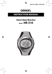
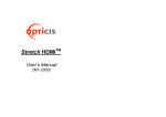
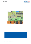
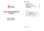
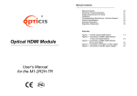
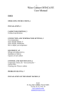
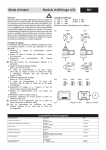
Manual Contents __________________________________________ Manual Contents Welcome!, Product Description (2 Pages) System Requirements for Setup Installation Troubleshooting, Maintenance, Technical Support Product Specifications (2 Pages) Warranty Information Regulatory Statements ® Stretch USB TM Pictorials Figure 1 – Mechanical Dimension of Modules and Connector Types Figure 2 – Optical USB Extension Cables plugging in an AC/DC Power Adaptor Figure 3 – Cross Section of Fiber-optic Bundled Cables Figure 4 – Cross Section of Hybrid Fiber-optic Bundled Cables User’s Manual (For Windows and Mac Systems) 1-0 Manual Contents 1-0 1-1 1-2 1-3 1-4 1-5 1-6 1-7 1-1 1-1 1-5 1-5 Welcome! Product Description TM Congratulations on your purchase of the Stretch USB M2-1x0 or M2-2x0 Optical USB (Universal Serial Bus) Extension Cable, compatible with Windows and Mac Systems. This manual contains information that will assist you in installing and operating the product. Product Description Shipping Group M2-1x0 or M2-2x0 Optical USB Extension Cable: One (1) unit DC power adapter: One (1) unit User’s Manual Quick Installation Note Model Identification M2-1x0 where “1” stands for pure fiber-optic cable extension M2-2x0 where “2” stands for hybrid fiber-optic cable extension For both model names, the last character “0” stands for being compatible with MS Windows and Mac systems. The letter ”x” has options that “0” stands for A plug-in (Upstream) to A receptacle (Downstream) connector and “1” stands for A plug-in (Upstream) to B plug-in (Downstream) connector. A receptacle M2-100 (A plug-A receptacle) A receptacle M2-200 (A plug-A receptacle) B plug M2-110 (A plug-B plug) B plug M2-210 (A plug-B plug) Figure 2 – Optical USB Extension Cables plugging in an AC/DC Power Adaptor Figure 1 – Mechanical Dimension of Modules and Connector Types 1-1 Welcome, Product Description 1-1 Welcome, Product Description (Continued) System Requirements for Setup Hardware requirements systems. No special requirements for memory size, CPU speed and chipsets, if you’ve already properly installed your USB controllers or cards. Most PCs are shipped to intrinsically embed in their own USB controller so that you don’t have to install any. Software requirements No special restrictions, if you’ve already properly installed your USB controller in your Windows or Mac Systems. Important: Please use the installation procedure below. Improper, or no operation may result if the start-up sequence is not correctly followed. You have to have a USB controller in compliance with USB-IF standard and USB “A” receptacles in your PC or Mac Installation Restriction of USB Hub Addition or Multiple Connection of M2-xx0 USB Extension cables in a row to a USB device: Opticis NOT guarantee using any additional hub before/after M2xx0 USB extension cables or such multiple connection. Precaution to install: NOT guarantee multiple connections of M2-xx0 cables or additional hubs. Refer to 1-5 Troubleshooting for such applications in inevitable case after confirming that each M2-xx0 cable works based on the following steps. Step 1 Carefully unpack the contents of the shipping group. Step 2 Connect an AC/DC power adapter to the downstream module of M2-1x0. In case of M2-2x0, using hybrid cable, plug an AC/DC power adapter into the power cord receptacle of its upstream module. Step 3 Plug the “A” plug-in of the upstream module of M2-xx0 into the USB “A” receptacle of PCs. Note: If you do this step while opening the Windows system manager, at the moment to plug in, you can see getting the system manager refreshed itself and it shows attaching a general USB hub under the USB controller. When you proceed with Step 3 in advance, you might find in a moment the system manager recognize as an unknown device, but at last recognize attaching a general USB hub under the USB controller. Step 4 Plug the “A” plug-in or “B” receptacle of your USB device to the “A” receptacle or “B” plug-in of the downstream module of M2-1x0 and M2-2x0. Then you can find attaching your device drive controller in the Windows system manager. IMPORTANT NOTE: when installing M2-xx0 cables, ensure not to bend them over the minimum bend radius and pull them over the tensile load as instructed in 1-6 Product Specifications. When operating, ensure not to put any sharp edge corner on the cables. 1-2 System Requirements for Setup 1-3 Installation Troubleshooting Product Specifications The generic USB hub under USB controller cannot be seen in Windows System Manager. If you cannot see it even after having installed as instructed in 1-3 Installation, try to deplug and replug the A plug-in of the upstream module of M2-xx0, while the power is being supplied to its downstream module. Or, deplug and replug the power plug-in of AC/DC power adapter from/to its downstream module. If proceeding not to see it, reboot the PC and re-install as instructed in 1-3 Installation. M2-1x0 Optical USB Extension Cable Your USB device connected to an M2-xx0 cable not works properly. Check at first if the generic USB hub is attached in Windows System Manager. If not, follow the above instruction after disconnecting your USB device. Not working yet even though succeeding attaching the hub, check if the device driver is installed in the Windows System Manger. If NOT, go to the website of manufacturer of your USB device to download its proper device driver and reinstall it. Or, contact the manufacturer. Want to use multiple connections in a row or USB hub additions. Opticis could guide, based on its evaluation results, that many USB devices would be allowed to use one (1) USB hub with M2-xx0 cables less than roughly 140 feet (43m) extension. It certainly relates to what USB devices and hubs are used. The multiple connections, assuming to use a hub, should be done for the total extension not to exceed roughly 150 feet (45m) long. When doing this, we strongly suggest checking attaching a USB controller in Windows System Manager every connection of a hub or an M2-xx0 cable. Maintenance No special maintenance is required for the optical USB extension cables and power supplies. Ensure that the cables and power modules are stored or used in a benign environment free from liquid or dirt contamination. Compliance with Low and Full-speed versions of USB standard: support USB1.0 (1.5Mbps) and USB 1.1 (12Mbps), fully implemented by fiber-optic communication. Extension limit: 50m (164feet). Fiber-optic Bundled Cable: Riser Jacket of retardant PVC employing 2 strands multimode glass of fibers having 62.5/125 m cores. The cross-sectional diagram is shown in figure 3. Tensile load: 1,200N Minimum bend radius: 6.8cm Outer diameter of cable: 4.5cm Mechanical specifications of modules Dimensions: see 1-1 Product Description Clamping strength to cable: 14kgf Environmental Specifications Operating temperature: -10°C to 55°C Storage temperature: - 10°C to 70°C Humidity: 5% to 95% AC/DC Power Adapter for M2-1x0 Power Input: AC 100-240V, 50/60Hz 0.1A Power Output: +5 V, 600 mA SMPS DC-power Adapter Cord DC Jack: Core is 5 V and outer is GND. KEVLAR There are no user serviceable parts. Refer all service and repair issues to Opticis. PVC COATING PVC COATING Technical Support and Service For commercial or general product support, contact your reseller. For technical service, contact Opticis by email [email protected] or visit its website at www.opticis.com 1-4 Troubleshooting, Maintenance, Technical Support PVC JACKET (NON FLAMMABLE) Figure 3 – Cross Section of Fiber-optic Bundled Cables 1-5 Product Specifications Product Specifications Warranty Information M2-2x0 Optical USB Extension Cable 1 (One) Year Warranty Compliance with Low and Full-speed versions of USB standard: support USB1.0 (1.5Mbps) and USB 1.1 (12Mbps), fully implemented by fiber-optic communication. Extension limit: 40m (150feet). Hybrid Fiber-optic Bundled Cable: Riser Jacket of retardant PVC employing 2 strands multimode glass of fibers having 62.5/125m core and 2 copper wires of 24 AWG. The cross sectional diagram is shown in figure 4. Tensile load: 1,200N Minimum bend radius: 11.5cm Outer diameter of cable: 6.8cm Mechanical specifications of modules Dimensions: see 1-1 Product Description. Clamping strength to cable: 14kgf Environmental Specifications Operating temperature: 0°C to 50°C Storage temperature: - 10°C to 70°C Humidity: 5% to 95% AC/DC Power Adapter for M2-2x0 Power Input: AC 100-240V, 50/60Hz 0.1A Power Output: +9 V, 600 mA SMPS DC-power Adapter Cord DC Jack: Core is 9 V and outer is GND. Opticis warrants this optical USB extension cable to be free from defects in workmanship and materials, under normal use and service, for a period of one (1) year from the date of purchase from Opticis or its authorized resellers. If a product does not work as warranted during the applicable warranty period, Opticis shall, at its option and expense, repair the defective product or part, deliver to customer an equivalent product or part to replace the defective item, or refund to customer the purchase price paid for the defective product. All products that are replaced will become the property of Opticis. Replacement products may be new or reconditioned. Any replaced or repaired product or part has a ninety (90) day warranty or the reminder of the initial warranty period, whichever is longer. Opticis shall not be responsible for any software, firmware, information, or memory data of customer contained in, stored on, or integrated with any products returned to Opticis for repair under warranty or not. Warranty Limitation and Exclusion Opticis shall have no further obligation under the foregoing limited warranty if the product has been damaged due to abuse, misuse, neglect, accident, unusual physical or electrical stress, unauthorized modifications, tampering, alterations, or service other than by Opticis or its authorized agents, causes other than from ordinary use or failure to properly use the Product in the application for which said Product is intended. Figure 4 – Cross Section of Hybrid Fiber-optic Bundled Cables 1-5 Product Specifications (Continued) 1-6 Warranty Information FCC/CE Statement © 2008 Opticis Co., Ltd. All Rights Reserved Revision 2.2 This device complies with part 15 and 2 of FCC Rules and with EN 55022/55024/61000-3 for CE certification. Operation is subject to the following two conditions: (1) this device may not cause harmful interference, and (2) this device must accept any interference received, including interference that may cause undesired operation. This equipment has been tested and found to comply with the limits for a Class B digital device for M21x0 and a Class A digital device for M2-2x0, pursuant to part 15 and 2 of FCC Rules and EN 55022/55024/61000-3 for CE certification. These limits are designed to provide reasonable protection against harmful interference when the equipment is operated in a residential installation. This equipment generates, uses, and can radiate radio frequency energy and. if not installed and used in accordance with the instruction guide, may cause harmful interference to radio communications. However, there is no guarantee that interference will not occur in a particular installation. If this equipment does cause harmful interference to radio or television reception, which can be determined by turning the equipment off and on, the user is encouraged to try to correct the interference by one or more of the following measures: Re-orient or relocate the receiving antenna. Increase the separation between the equipment and the receiver. Connect the equipment into an outlet on a circuit different from that to which the receiver is connected. Consult a service representative for help. Properly shielded and grounded cables and connectors must be used in order to comply with FCC/CE emission limits. Changes or modifications not expressly approved by the party responsible for compliance could void the user s authority to operate the equipment. Opticis Locations Opticis Co., Ltd. #501 Byucksan Technopia, 434-6, Sangdaewon-Dong, Chungwon-Ku, Sungnam City, Kyungki-Do, 462-120, South Korea Tel: +82 (31) 737-8033 Fax: +82 (31) 737-8079 For order support, please contact your Distributor or Reseller. 1-7 Regulatory Statements For technical support, check with the Opticis web site www.opticis.com or contact [email protected]