1
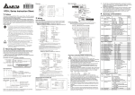
Operation Manual for Peristaltic Pump PP-%/ PLEASE READ THIS MANUAL CAREFULLY BEFORE OPERATION 3, Hagavish st. Israel 58817 Tel: 972 3 5595252, Fax: 972 3 5594529 [email protected] MRC.VER.01-9.12 Introduction PP-B-35L peristaltic pump is ideal for high flow rates fluids transfer, driven by the AC motor and the frequency converter control the speed. Its operation is simple and reliable. The pump delivers flow rates from 0.8 to 35L/min. Through the transparent front cover, the running status of the pump head is visible. The speed, running direction and run/stop of the pump are controlled manually by membrane key or automatically by external control interface. We recommend you not use it outdoors. 9. Handwheel: Turn the handwheel can move the compression block. Loose the handwheel for loading the tubing while tighten the handwheel when working. 10. Power Socket/Switch: Connect the power 11.Locking Knob for Handwheel: For locking the handwheel. Prevent the handwheel from loosing when working. 12.Machine Base: Install the motor, pump head and frequency Converter. 13.Fasten Knob for Compression block: Tighten the compression block to prevent it from shake after the compression block has been adjusted. 1 13 Introduction of Frequency Converter: (For details please see the <SE Series Frequency Converter Operating Manual >) 6 2 5 12 11 4 10 Important information of operation: Operating Conditions: Temperature -10 ℃ to 40 ℃ Relative humidity < 90% (no dew) Avoid rain sprinkle or humid condition. Avoid solarization. Preserve from aggressive liquids and gas. The location ofi t should be easy for heat emission. It can be taken off from the peristaltic pump and install to other places which is easy to operate. 3 8 1. AC motor: supply the pump head with power 2. Frequency Converter: control the speed, rotating direction and Run/Stop of the pump. 3. Rotor Assembly: Extrude the tubing to deliver the fluids. It's driven by the motor. 4. Front Cover: Protective function. The transparent cover is easy for observing the running status of the pump head. 5. Locking Knob: Fix the front cover and press the tubing tightly after loading the tubing. 6. Tubing Clamp: Can load four different diameter tubing. 7. Compression Block: Extrude the tubing to deliver the fluids together with the rotor assembly. 8. Star Handle: Fix the front cover. 1 1 2 3 STOP ▲ ▲ 9 7 RUN STOP MODE RESET PROG DATA 4 5 8 6 7 2 Operation Panel and Terminal 1.LED Display: Display the Stop the pump. Tighten the [Locking Knob for Handwheel 10] to working status and running lock the handwheel. Tighten the [Fasten Knob for Compression Block 13] to decrease the running noise of the pump. parameters of the frequency converter. 2.Speed Adjustment/ Data Input: Adjust the motor speed in running status and input the data in altering the parameters of the frequency converter. Note: Over-squeezing the tubing may cause the decrease of its service life and influence the working status of the pump. 3. Run/Stop: Control the motor to run and stop. 4. Mode/Reset: Switch the displays of the frequency converter. Basic operation of the Frequency Converter 5. Prog/Data: Setting data and confirmation. The LED display of frequency converter lights when the power 6. External Control Terminal: The signal wire interface when using supply switches on. But the pump is in stopping status. Run /stop: Press [Run/Stop] key, the [Run] indicator lights and external control (unlock the password setting first) 7.Power /Motor Terminal: Power input and motor output the pump runs. Press the [Run/Stop] key again the pump stops. Speed Adjustment: Press Speed Adjustment/ Data Input Keys 2 to connection wire terminal. 8. 485 Communication Interface change the speed of the pump. The LED displays the value of the frequency. The actual speed (rpm) is about 5.8 times of frequency value. Operation Panel Direction: Press the [MODE/RESET] key continuously till the LED Tubing Loading Shut off the power supply (Can not do any operations such as changing tubing when the frequency converter has displays). Loose [Locking Knob for Handwheel 10], Loose [Fasten Knob for Compression Block 13], turn the [Handwheel 9] counter clockwise to loose the compression block. Loose [Locking Knob 5] completely. Pull out [Star Handle 8]. Take off [Front Cover 4]. Insert one side of the tubing to the corresponding slot of the [Tubing Clamps 6]. Round the tubing around the outside of the three rollers. Insert the tubing to another corresponding slot of the [Tubing Clamp6]. Adjust the tubing to make it stretch properly. Pull out [Star Handle 8]. Install the [Front Cover 4]. Tighten [Locking Knob 5]. displays [Frd] when the [FWD] indicator which is in the left side of LED screen lights. Press the Speed Adjustment/ Data Input Keys 2, the LED displays [REV]. The [REV] indicator lights at the same time and the motor rotates reversely. When the [REV] indicator which is in the left side of the LED screen lights, switch to [FWD] mode in the same way. Display Convert: Press the [MODE/RESET] key continuously can show the following parameters alternatively: F: setting the frequency; H: the actual running frequency; A: the current of the motor. Frequency Converter Troubleshooting: Frequency converter has many warning and protective functions. The motor will stop automatically when the pump is in abnormal status. Eliminate the Occlusion Adjustments abnormal status and press the [MODE/RESET] key the pump can Turn the [Handwheel 9] clockwise. Tighten the tubing slightly. work continuously. The letters or the symbols on the LED display Start the peristaltic pump. If the fluids can't be delivered, turn the show the information of abnormal status. For details please see handwheel continuously until the fluids happen to be delivered. the <SE Series Frequency Converter Operating Manual > 3 4 Acceptable Tubing and Flow Rates 30 ~ 360 rpm Speed Tubing Technical Specifications 92# Inner Diameter × Wall Thickness 25.4 × 4.8 ( mm ) Flow Rates 3 ~ 35 (L/min) Functions 88# 90# 86# 19 × 4.8 12.7 × 6.3 9.5 × 6.3 2.2 ~ 26.4 1 ~ 12 0.55 ~ 6.6 External Control Function External analog signal controls the speed: The keys on the panel of frequency converter are invalid by setting the parameters (needs unlock). The speeds are controlled by external control terminals. 485 communication interface: By setting the parameters (needs unlock) the master computer can control the pump directly by communication interface. Note The frequency converter has many parameter setting items. To avoid misoperation we lock the parameter settings by password. We set the max. frequency of the frequency converter is 65 Hz and the max. speed is 370 rpm. If other parameters setting are needed please ask for password from our company. But we won't take any responsibility if damage occurs because of parameters changing. Maintenance 1. When the pump is idle, we recommend you to release the tubing from pressure. This helps to protect the tubing from unnecessary strain and prolongs its service life 2. Keep rollers clean and dry. This will prolong the service lives of tubing and pump head. Please wipe out any liquid splashed on the roller as soon as possible or it will lead to unnecessary damage 3. The surface of motor and the pump head are not organic solvent and aggressive liquids resistant. Please pay attention when using. 4. We recommend you to smear silicon oil on the surface of the tubing to prolong its service life. Speed Control: Frequency converter speed adjustment Display: LED displays current running status Direction Control: CW and CCW reversible External Control: Speed control, cw/stop, ccw/stop (need unlock) Communication Function: RS485 (need unlock) Specifications Speed: 30 - 350 rpm, reversible Speed Precision: 0.6 rpm Speed Adjusting: Membrane key adjustment Display Mode: LED display Applicable Power: AC 220V +/- 10% 50Hz+/-1Hz AC 110V +/- 10% 60Hz+/-1Hz Power Consumption: < 375 W Operating Condition: Temperature 0 to 40 ℃ Relative humidity < 80% Dimensions (L × W × H): 530 × 375 × 260 (mm) Weight: 26 Kg IP Rating: IP 31 Warranty The warranty period for this product is one year. If repair or adjustment is necessary within the warranty period, the problem will be corrected at no charge if it is not due to misuse or abuse on your part, as determined by the manufacturer. Repair costs outside the warranty period, or those resulting from product misuse or abuse, may be invoiced to you. 5 6 Dimension AC line input terminals grounding Single phase models input from R/L1, S/L2 12. If the AC drive is installed in the 13. Capacitor or L-C Filter (Inductanc e-Capacitance) or R-C Filter (Resistance-Capacitance). When using a GFCI (Ground Fault Circuit Interrupt), select current sensor with minimum current 20 0mA, and minimum detection time 0.1-second to avoid nuisance tripping. 4 Summary of Parameters R/L1 S/L2 T/L3 UP/DOWN LED display STOP RUN FWD REV Function Display key Data MODE RESET VFD-L Series Instruction Sheet 1 Frequency setting VFD-L MAX. 0.75KW 230V IPHASE WARNING Preface RA RC 3 Read the user manual before operation. + 10V AVI Reverse/Stop 1:+EV 2:GND 6 ←1 3:SGRS-485 4:SG+ Communication Main circuit (power) port terminals Control circuit terminals 0-01 Rated current display (Read only) 0-02 Parameter reset 0-03 Start-up display of AC drive 4: 400W 1: 40W 5: 750W 2: 100W 6: 1.5KW 3: 200W 40W: 0.4A 400W: 2.5A 100W: 0.8A 750W: 4.2A 200W: 1.6A 1.5K: 7.0A 10: Reset Parameters to Factory Setting 0: F (Frequency command) 1: H (output frequency) 0-06 0-07 RA RC +15V AVI M0 M1 M2 M3 GND Shielded leads Common signal Multi-function input selection 3 Multi-function input selection 2 Multi-function input selection 1 Multi-function assistant terminal Power for speed setting Analog Voltage, current frequency command VR Relay Multi-function indication output contact (120VAC /DC28V 3A) R/L1 U/T1 S/L2 S/L2 V/T2 IM 3~ T/L3 T/L3 W/T3 Motor MCCB Power supply +15V 30mA(MAX) +15V M0 Reverse/Stop M2 Multi-function indication output contacts 120VAC/28VDC 3A Factory default: Fault Indication RJ-11 1:+EV 2:GND 3:SG6 ←1 4:SG+ RS-485 Communication +15V Main circuit (power) Power supply port terminals +15V 30mA(MAX) Control circuit terminals AVI Shielded leads GND Multi-step 1 M3 GND VR: 3K ~ 5K Ω 3 1 VR 3 2 2 VR Master Freq. setting Analog voltage 0~10VDC VR :3K ~ 5K Ω Analog current RA RC M1 Reset 1 Wiring Notes: PLEASE READ PRIOR TO INSTALLATION. Do not connect the AC input to any of the U/T1, V/T2, W/T3 terminals, as it will damage the AC drive.. Ensure all screws are tightened to the proper torque rating. 1. During installation, follow all nati onal and local electrical, construction, and safety codes for the country the drive is to be installed in. 2. Ensure the appropriate protective dev ices (circuit breaker or fuses) are connected between the power supply and AC drive. 3. Make sure that the leads are connected correctly and the AC drive is 4. 5. below. Ensure there are no ground loops. 6. REV/STOP Factory setting RESET Multi-step 1 Digital Signal Common *Don't apply the mains voltage directly to above terminals. Main circuit wiring PNP Mode for models: VFD004L21D, VFD004L21E, VFD007L21D, VFD007L21E +10V M0 M1 M2 M3 GND E FWD/STOP Factory setting REV/STOP RESET Multi-step 1 +15V 7. M0 M1 M2 M3 8. 9. GND *Don't apply the mains voltage directly to above terminals. E 10. When the AC drive output terminals U/T1, V/T2, and W/T3 are connected to the motor terminals U, V, and W, respectively, the motor will rotate counterclockwise (as viewed from the shaft ends of the motor) when a forward operation command is received. To reverse the direction of motor rotation, switch over any of the two motor leads. Make sure that the power is capable of supplying the correct voltage and required current to the AC drive. Do not attach or remove wiring when power is applied to the AC drive. Do not monitor the signals on the circuit board while the AC drive is in operation. Route the power and control wires separately, or orthogonal to each other. install it as close as possible to AC lowering the Carrier Frequency. 0 1.0 drive. EMI can also be reduced by Read only 0 ~ 999 #.# 0 9 9 9 ~ 0 0 Group 1: Basic Parameters . r P 1-00 1-01 1-02 1-03 1-04 1-05 1-06 1-07 1-08 1-09 1-10 1-11 1-12 1-13 1-14 1-15 1-16 1-17 1-18 s n Maximum operation Fr eq. Maximum setting Freq. Maximum output voltage Mid-point freq. Mid-point voltage Minimum output freq. Minimum output voltage Upper bound of freq. Lower bound of freq. Accel time 1 (Tacc1) Decel time 1 (Tdec1) Accel time 2 Decel time 2 JOG Accel time JOG Decel time JOG frequency Auto-accel/decel S-curve setting in acceleration S-curve setting in deceleration o i t c n u F s g Functions 2-00 Source of frequency command 2-01 Source of operation command 2-02 2-03 2-04 Stop method Carrier freq. Reverse operation inhibit 2-05 ACI (4 ~ 20mA) input loss detection 2-06 Line Start Lockout Factory n i t t e S Setting 60.0 60.0 220 1.0 12.0 1.0 12.0 100 0.0 10.0 10.0 10.0 10.0 10.0 10.0 6.0 0 50.0 ~ 400Hz 10.0 ~ 400Hz 2.0 ~ 255V 1.0 ~ 400Hz 2.0 ~ 255V 1.0 ~ 60.0Hz 2.0 ~ 255V 1 ~ 110% 0 ~ 100% 0.1 ~ 600 Sec 0.1 ~ 600 Sec 0.1 ~ 600 Sec 0.1 ~ 600 Sec 0.1 ~ 600 Sec 0.0 ~ 600 Sec 1.0Hz~400Hz 0: Linear Accel/Decel 1: Auto accel, linear decel 2: Linear accel, auto decel, 3: Auto Accel/Decel 4: Linear accel. Auto decel, stall prevention during deceleration 5: Auto accel. Auto decel, stall prevention during deceleration 7 ~ 0 0 7 ~ 0 0 Group 2: Operation Method Parameters Forward running Wiring for NPN mode and PNP mode FWD/STOP Ω.) properly grounded. (Ground resistance should not exceed 0.1 Use ground leads that comply with AWG/MCM standards and keep them as short as possible. Multiple VFD-L units can be install ed in one location. All the units should be grounded directly to a common ground terminal. The VFD-L ground Software version Password input Password 0-08 Pr. NOTE: Do not plug in a Modem or telephone line to the RS-485 communication port, permanent damage may result. Terminals 1 & 2 are the power source for the optional copy keypad and should not be used while using RS-485 communication. *If the AC Drive model is VFD004L21E, VFD007L21E, please use power terminals R/L1 and S/L2. *If the AC Drive model is VFD004L21D, VFD007L21D, 1-phase/3 phase power may be used on R/L1, S/L2, T/L3. When VFD004L21D/VFD007L21D use 1-phase power, please select any two of the three input terminals R/L1, S/L2, T/L3. NPN Mode for models: VFD002L11A, VFD002L11B, VFD002L21A, VFD002L21B, VFD004L11A, VFD004L11B, VFD004L21A, VFD004L21B, VFD007L21A, VFD007L21B, VFD015L23A 0 0.1 ~ 160 Main Circuit Power R/L1 0 1: Display Counter Value (C) 2: Display Process Operation (1=tt) 3: Display DC-BUS voltage (U) 4: Display output voltage (E) Figure 4 for models: VFD004L21D, VFD004L21E, VFD007L21D, VFD007L21E Wire Gauge:22-24AWG, Torque: 4Kgf-cm Figure 2 for models of VFD-L series VFD004L21D, VFD004L21E, VFD007L21D, VFD007L21E VFD-L series If there is any nameplate information not corresponding to your purchase order or any problem, please contact your distributor. 120VAC/28VDC 3A Factory default: Fault Indication NOTE: Do not plug in a Modem or telephone line to the RS-485 communication port, permanent damage may result. Terminals 1 & 2 are the power source for the optional copy keypad and should not be used while using RS-485 communication. *If the AC Drive model is VFD002L11A/B, VFD004L11A/B, VFD002L21B, VFD004L21B or VFD007L21B, please use power terminals R/L1 and S/L2. *If the AC Drive model is VFD002L21A, VFD004L21A or VFD007L21A, 1-phase/3 phase power may be used on R/L1, S/L2, T/L3. When VFD002L21A/VFD004L21A or VFD007L21A use 1-phase power, please select any two of the three input terminals R/L1, S/L2, T/L3. *If the AC Drive model is VFD015L23A, single phase power is not allowed. version D: PNP Mode A: standard B: with EMI Filter E: PNP Mode with EMI Filter Input voltage Production number Production week Production year 2006 Production factory (T: Taoyuan, W: Wujuang) Multi-function indication output contacts RJ-11 M3 GND Power supply for Potentiometer +10V 10mA(MAX) +10V 3 Master Freq. setting 2 AVI Analog voltage VR 0~10VDC 1 VR :3K ~5K Ω GND Analog current MADE IN XXXXX Serial Number Explanation RC M2 Common Signal Model Explanation T 6 10 001 RA M0 M1 Reset Multi-step 1 007L21AT101001 Variable Frequency Drive Identity code of drive (Read only) Common signal Factory default settings Forward/Stop Relay Multi-function input selection 3 Motor Multi-function input selection 2 W/T3 Multi-function input selection 1 T/L3 Multi-function assistant terminal T/L3 Power for speed setting IM 3~ Analog Voltage, current frequency command U/T1 V/T2 MCCB Forward/Stop 007:0.75kW 015:1.5kW Torque: 4Kgf-cm RA RC +10V AVI M0 M1 M2 M3 GND Multi-function indication output contact (120VAC /DC28V 3A) R/L1 S/L2 R/L1 Factory default settings 002:0.2kW 004:0.4kW Wire Gauge:22-24AWG, 0-00 Factory Setting Settings 3: A (output current) S/L2 MODE :VFD007L21A INPUT :1PH/9.7A 3PH/5.1A 200-240V 50-60Hz OUTPUT :3PH 0-240V 4.2A 1.6kVA 1HP Freq. Range:1.0~400Hz Applicable motor capacity Figure 3 for models: VFD002L11A, VFD002L11B, VFD002L21A, VFD002L21B, VFD004L11A, VFD004L11B, VFD004L21A, VFD004L21B, VFD007L21A, VFD007L21B, VFD015L23A The parameter may be set during operation. Functions Main Circuit Power Nameplate Information: Example of 1HP230V VFD 007 L 21 A Grounding Motor connections U/T1, V/T2, W/T3 Control circuit wiring Figure 1 for models of VFD-L series VFD002L11A, VFD002L11B, VFD002L21A, VFD002L21B, VFD004L11A, VFD004L11B, VFD004L21A, VFD004L21B, VFD007L21A, VFD007L21B, VFD015L23A This VFD-L AC drive has gone through rigorous quality control tests at the factory before shipment. Since many things may happen during shipping, please check for the following after receiving the AC motor drive. ◎ Inspect the unit to insure it was not damaged during shipment. ◎ Make sure that the part number indicated on the nameplate corresponds with the part number of your order. DELTA ELECTRONICS, INC. U/T1 V/T2 W/T3 Basic Wiring Diagram Users must connect wiring according to the circuit diagram shown below. Please follow all National and State wiring codes, when wiring the VFD-L. Receiving and Inspection Bar Code Serial NO. Pr. RS485 communication port Wiring AC input power must be disconnected before any maintenance. Do not connect or disconnect wires while power is applied to the circuit. Only qualified technicians should perform maintenance on the VFD-L. A charge may still remain in the DC-link capacitor with hazardous voltages even after the power has been turned off. To avoid personal injury, do not remove the cover of the AC drive until all “DISPLAY LED” lights on the digital keypad are off. Please note that there are live components exposed when the AC drive is open,. Be careful to not touch these live parts. The AC drive may be destroyed beyond repair if power is misapplied to the input/output terminals. Never connect the AC drive output terminals U/T1, V/T2, W/T3 directly to the AC main circuit power supply. There are highly sensitive MOS components on the printed circuit boards. These components are especially sensitive to static electricity. To avoid damaging these components, do not touch the circuit boards with metal objects or your bare hands. Ground the VFD-L using the ground terminal. The grounding method must comply with the laws of the country where the AC drive is to be installed. AC Drive Model Input Spec. Output Spec. Output Freq. Range Group 0: User Parameters The signal selection for AVI to input DC0~+10V or 4~20 mA RS-485 M0 M1 M2 M3 GND RUN/STOP Motor capacity and input power Do not connect AC power to output terminals (U,V,W). Do not inspect components until LEDs V I Thank you for choosing DELTA’s VFD-L seri es AC Drive. The VFD-L series is manufactured using high-quality components, material and incorporating the latest microprocessor technology available. This manual will help in the installati on, parameter setting, troubleshooting, and daily maintenance of the AC motor drive. To guarantee safe operation of the equipment, read the following safety guidelines before connecting power to the AC motor drive. Keep this operating manual handy and distribute to all users for reference. Important Notes: 2 PROG DATA RUN STOP MIN. place where a load reactor is needed, Settings 0: Digital keypad 1: 0 ~ 10V from AVI 2: 4 ~ 20mA from AVI 3: Controlled by V.R on drive 4: RS-485 communication interface 0: By digital keypad 1: By external terminals, keypad STOP enable 2: By external terminals, keypad 3: By RS-485 communication interface, keypad STOP enable 4: By RS-485 communication interface, keypad STOP disable 0: Ramp stop 1: Coast stop 3 ~10K Hz 0: Enable reverse 1: Disable reverse 2: Disable forward 0: Decel to 0Hz 1: Stop immediately, display EF 2: Run with the last freq. 0: Enable 1: Disable Factory Setting 0 0 0 10 0 0 0 0: not used 1: AC drive operational 2: Max. Output Freq. Attained 3: Zero Speed 4: Over Torque 5: Base-Block (B.B.) 6: Low Voltage Detection 7: AC Drive Operation Mode 8: Fault Indication 9: Desired Freq. Attained 10: PLC Program Running 11: PLC Program Step Complete 12: PLC Program Complete 13: PLC Program Operation Pause 14: Terminal Count Value Attained 15: Preliminary Count Value Attained 16: Ready State Indicator 8 Functions Potentiometer bias freq. Potentiometer bias a4-01 polarity Potentiometer freq. a4-02 gain Potentiometer 4-03 reverse motion enable a4-00 4-04 4-05 4-06 Multi-function input terminal1 (M1) (d 0~d 20) Multi-function input terminal 2(M2) Multi-function input terminal 3(M3) (d 0, d 4~d 20) Settings 0.0~350Hz 6-05 6-07 6-09 6-10 6-11 Factory setting 100 0: not used 1: reverse motion enable 2: forward motion only 0: not used 1: M0: FWD/STOP, M1: REV/STOP 2: M0: RUN/STOP, M1: FWD/REV 3: M0, M1, M2: 3-wire operation control mode 4: External fault, normally open (N.O.) 5: External fault, normally closed (N.C.) 6: RESET 7: multi-step speed command 1 8: multi-step speed command 2 9: jog operation 10: accel/decel speed inhibit 11: first or second accel/decel time selection 12: base-block (B.B.),normally open (N.O.) 13: base-block (B.B.),normally closed (N.C) 14: increase master freq. 15: decrease master freq. 16: run PLC program 17: pause PLC 18: counter trigger signal 19: counter reset 20: select ACI/deselect AVI 0 Pr. 5-04 5-05 5-06 5-07 5-08 Functions 1st step speed freq. 2nd step speed freq. 3rd step speed freq. PLC mode PLC forward/reverse motion Time duration step 0 Time duration step 1 Time duration step 2 Time duration step 3 Settings 0.0 ~ 400Hz 0.0 ~ 400Hz 0.0 ~ 400Hz 0: Disable PLC operation 1: Execute one program cycle 2: Continuously execute program cycles 3: Execute one program cycle step by step (separate by STOP) 4: Continuously execute one program cycle step by step (separate by STOP) 0 ~ 15 (0: Forward, 1: Reverse) 0 ~ 65500 Sec 0 ~ 65500 Sec 0 ~ 65500 Sec 0 ~ 65500 Sec 6-00 6-01 6-02 Functions 1 Over-Voltage Prevention Level Over-current Prevention Level Over-torque detection 0:disable 350~410V 0: disable 20~200% 0:disable 1:enable during constant speed operation and continues until the continuous limit is reached. 2:enabled during constant speed operation and halted after detection. 150 0.1 ~ 10.0 Sec 0.1 0: Not used 1: Act with standard motor 2: Act with special motor 0 30~600 Sec 60 0 Group 7: Motor Parameters Pr. Functions a7-00 a7-01 a7-02 a7-03 Motor rated current Motor no-load current Torque compensation Slip compensation Settings 30~120 % 0 ~ 90 % 0 ~ 10 0.0 ~ 10.0 Functions 8-00 8-01 6 8-02 8-03 8-04 DC braking voltage level DC braking time during start-up DC braking time during stopping Start-point for DC braking Momentary power loss 7 8-05 8-06 8-07 Factory Setting 0.0 0.0 0.0 0 8-08 8-09 8-10 8-11 8-12 8-13 8-14 8-15 8-16 8-17 0 0 0 0 0 Settings 6-12 Pr. Group 6: Protection Parameters Pr. 30 ~ 200% Factory Setting 85 50 1 0.0 Group 8: Special Parameters Group 5: Multi-step Speed and PLC Parameters 5-00 5-01 5-02 5-03 3:enabled during accel and continues before continuous output time limit is reached. 4:enabled during accel and halted after over-torque detection. 0: No fault occurred 1: oc (over current) 2: ov (over voltage) 3: oH (over heat) 4: oL (over load) 5: oL1 (electronic thermal) 6: EF (external fault) 7: Reserved 8: Reserved 9: ocA (current exceed during acceleration) Sixth most recent fault 10: ocd (current exceed during deceleration) record 11: ocn (current exceed during steady state) 6-08 0 1~200% Electronic thermal characteristic Present fault record Second most recent fault record Third most recent fault record Forth most recent fault record Fifth most recent fault record 6-06 0.0 0: positive bias 1: negative bias Over-torque detection level Over-torque detection time Electronic thermal overload relay 6-03 6-04 Group 4: Input Function Parameters Pr. 6-02 Factory Setting Factory Setting Max. allowable power loss time B.B. time for speed search Max. speed search current level Skip freq. 1 upper bound Skip freq. 1 lower bound Skip freq. 2 upper bound Skip freq. 2 lower bound Skip freq. 3 upper bound Skip freq. 3 lower bound Auto restart after fault AVR function Dynamic braking voltage DC braking lower bound limit 0 0 ~ 30% Factory Setting 0 0.0 ~ 60.0 Sec 0.0 0.0 ~ 60.0 Sec 0.0 0.0 ~ 400.0 Sec 0: Stop operation after momentary power loss. 1: Continues after momentary power loss, speed search starts with master freq. 2: Continues after momentary power loss, speed search starts with min. output freq. 0.0 0 0.3 ~ 5.0 Sec 2.0 0.3~5.0 Sec 0.5 30~200% 150 0.0~400 Hz 0.0~400 Hz 0.0~400 Hz 0.0~400 Hz 0.0~400 Hz 0.0~400 Hz 0~10 0: AVR function enable 1: AVR function disable 2: AVR function disable when decel 350 ~ 450V 0.0 0.0 0.0 0.0 0.0 0.0 0 2 380 0.0 ~ 400 Hz 0.0 Group 9: Communication Parameters Pr. Functions a9-00 Communication address a9-01 Transmission speed a9-02 Transmission fault treatment 390 170 Settings a9-03 a9-04 5 Modbus communication watchdog timer Communication protocol Settings 1 ~ 247 0: Baud rate 4800 1: Baud rate 9600 2: Baud rate 19200 0: Warn and continue running 1: Warn and ramp to stop 2: Warn and coasting stop 3: No warn and keep running 0: Disable 1~20: 1 ~ 20 Sec 4: 8,E,1 ASCII mode 5: 8,O,1 0: 7,N,2 RTU mode 1: 7,E,1 6: 8,N,2 2: 7,O,1 7: 8,E,1 3: 8,N,2 8: 8,O,1 Factory Setting 1 1 0 0 0 Troubleshooting and Fault Information The VFD-L AC drive has a comprehensive fault diagnostic system that includes several different alarms and fault messages. Once a fault is detected, the corresponding protective functions will be activated. The following faults are displayed on the AC drive digital keypad. The six most recent faults can be read on the digital keypad display by viewing Pr.6-07 to Pr.6-12. NOTE: faults can be cleared by pressing the Reset key on the keypad or Input Terminal. Common Problems and Solutions Fault Name Fault Descriptions Fault Name Corrective Actions 1. Check whether the motors horsepower corresponds to the AC drive output power. 2. Check the wiring connections between the AC drive and motor for possible short circuits. 3. Increase the Acceleration time (Pr.1-09, The AC drive detects an Pr.1-11). abnormal increase in 4. Check for possible excessive loading current. conditions at the motor. 5. If there are any abnormal conditions when operating the AC drive after the short-circuit is removed, the drive should be sent back to manufacturer. 1. Check whether the input voltage falls within The AC drive detects that the DC bus voltage the rated AC drive input voltage. has exceeded its 2. Check for possible voltage transients. 3. Bus over-voltage may also be caused by maximum allowable value. motor regeneration. Increase the decel time. 1. Ensure that the ambient temperature falls within the specified temperature range. 2. Make sure that the ventilation holes are not The AC drive obstructed. temperature sensor 3. Remove any foreign objects on the heat sink detects excessive heat. and check for possible dirty heat-sink fins. 4. Provide enough spacing for adequate ventilation. The AC drive detects that the DC bus voltage Check whether the input voltage falls within the has fallen below its rated AC drive’s input voltage. minimum value. 1. Check for possible motor overload. 2. Check electronic thermal overload setting. Internal electronic 3. Increase motor capacity. overload trip 4. Reduce the current level so that the drive output current does not exceed the value set by the Motor Rated Current Pr.7-00. The external terminal When external terminal EF-GND is closed, the EF-GND goes from OFF output will be turned off. (under N.O.E.F.) to ON. Motor overload. Check 1. Reduce the motor load. the parameter settings 2. Adjust the over-torque detection setting to an ( Pr.6-03 to Pr.6-05) appropriate setting. 1. Check for possible poor insulation at the Over-current during output line. acceleration: 2. Decrease the torque boost setting in Pr.7-02. 1. Short-circuit at motor 3. Increase the acceleration time. output. 2. Torque boost too high. 4. Replace with the AC drive with one that has a 3. Acceleration time too higher output capacity (next HP size). short. 4. AC drive output capacity is too small. Over-current during 1. Check for possible poor insulation at the deceleration: output line. 1. Short-circuit at motor 2. Increase the deceleration time. output. 3. Replace with the AC drive with one that has a 2. Deceleration time too higher output capacity (next HP size). short. 3. AC drive output capacity is too small. External Base Block. 1. When the external input terminal (B.B) is active, the AC drive output will be turned off. AC drive output is 2. Disable this connection and the AC drive will turned off. begin to work again. 1. Check for possible poor insulation at the Over-current during output line. steady state operation: 2. Check for possible motor stall. 1. Short-circuit at motor 3. Replace with the AC drive with one that has a output. higher output capacity (next HP size). 2. Sudden increase in motor loading. 3. AC drive output capacity is too small. 1. Switch off power supply. Internal memory IC can 2. Check whether the input voltage falls within not be programmed. the rated AC drive input voltage. 3. Switch the AC drive back on. 1. Check the connections between the main Internal memory IC can control board and the power board. not be read. 2. Reset drive to factory defaults. 1. Switch off power supply. Drive’s internal circuitry 2. Check whether the input voltage falls within abnormal. the rated AC drive input voltage. Switch on the AC drive. Fault Descriptions Corrective Actions Auto accel/decel failure Don’t use the function of auto acceleration/ deceleration. Hardware protection failure Software protection failure Communication Error The AC drive detects excessive drive output current. 6 Return to the factory. Return to the factory. 1. Check the connection between the AC drive and computer for loose wires. 2. Check if the communication protocol is properly set. 1. Check whether the motor is overloaded. 2. Reduce torque compensation setting as set in Pr.7-02. 3. Increase the AC drive’s output capacity. Note: The AC drive can withstand up to 150% of the rated current for a maximum of 60 seconds. Standard Specifications Voltage Class Model Number VFD-XXXLXXA/B Applicable Motor Output (kW) Rated Output Capacity (KVA) Rated Output Current (A) Output Rating 1.0 ~ 400 Hz 0 ~ 999 0 ~ 999 Over-torque detection Settings Max. Output Voltage (V) Rated Frequency (Hz) Rated Input Current (A) Power 3-03 Desired freq. attained Terminal count value Preliminary count value Multi-function (relay output) Settings Functions Input voltage Tolerance Frequency tolerance Control Characteristics 3-00 3-01 3-02 Functions Pr. Operating Characteristics Pr. Factory Setting 1.0 0 0 Environment Group 3: Output Function Parameters Control system Output Frequency Resolution Overload Endurance Accel/Decel Time V/F pattern Stall Prevention Level Keypad Operation Setting 230V 004 002 004 007 015 0.2 0.4 0.2 0.4 0.7 1.5 0.6 1.0 0.6 1.0 1.6 2.7 1.6 2.5 4.2 7.0 1.6 2.5 3-phase corresponds to double input voltage Three-phase corresponds to input voltage 1.0~400Hz 6 9 4.9/1.9 6.5/2.7 9.7/5.1 Ì/9 Single phase 3-phase Single / 3-phase 90~132V 180~264V 180~264V 50/60Hz 50/60Hz 50/60Hz ±5% SVPWM (Sinusoidal Pulse Width Modulation, carried frequency 3kHz~10kHz) 0.1Hz Torque Characteristics Frequency Setting 115V 002 External Signal Keypad External Signal Including the auto-torque, auto-slip compensation, starting torque can be 150% at 5 Hz 150% of rated current for 1 minute 0.1~600Sec. (can be set individually) V/F pattern adjustable 20~200%, setting of Rated Current Setting by ▲▼ keys or V.R Potentiometer-5KΩ/0.5W, DC 0 ~ +10V (input impedance 47KΩ), 4~20mA (output impedance 250Ω), multi-function inputs1 to 3 (3steps, JOG, UP/DOWN command), communication setting Setting by RUN//STOP keys M0,M1,M2,M3 can be combined to offer various Signal modes of operation, RS-485 communication port Multi-step selection 0 to 3, Jog, accel/decel inhibit, Multi-function Input Signal first/second accel/decel switch, counter, PLC Operation, external Base Block (NC,NO) selection AC Drive Operating, Frequency Attained, Non-zero Multi-function Output Signal speed, Base Block, Fault Indication, Local/Remote indication, PLC Operation indication. AVR, S-curve, Over-Voltage Stall Prevention, DC Braking, Fault Records, Adjustable Carried Frequency, Starting Frequency Setting of DC Other Function Braking , Over-Current Stall Prevention, Momentary Power Loss restart, Reverse Inhibition, Frequency Limits, Parameter Lock/Reset Over Voltage, Over Current, Under Voltage, Protection Overload, Electronic thermal, Overheating, Self-testing Other Including EMI Filter Cooling Forced air-cooling Altitude 1,000 m or below, keep from corrosive Installation Location gasses, liquid and dust -10℃-40℃ (Non-Condensing and not frozen) Ambient Temperature -20℃ to 60℃ Storage Temperature Ambient Humidity Below 90%RH (non-condensing) 9.80665m/s2(1G) less than 20Hz, 5.88m/s2 (0.6Gat) Vibration 20 to 50Hz