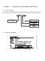
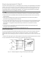
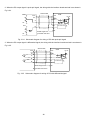
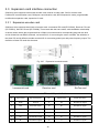
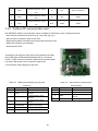
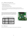
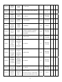
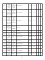
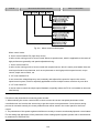
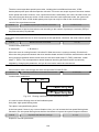
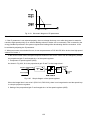
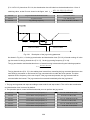
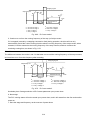
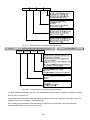
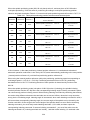
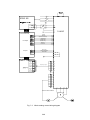
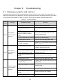
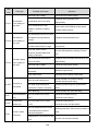
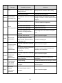
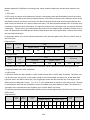
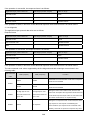
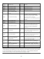
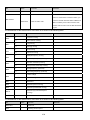
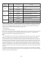
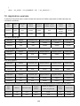
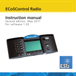
1
SV-Master Series Servo Drive
User Manual
Document Version:
Archive Date:
BOM Code:
V1.0
2014/05/23
R29090527
Shenzhen Megmeet Drive Technology Co., Ltd. provides full technical support for our
customers,customers can contact local Megmeet offices or customer service centers, or
directly contact Megmeet headquarters.
Shenzhen Megmeet Drive Technology Co., Ltd.
All rights reserved. The contents in this document are subject to change without notice.
Shenzhen Megmeet Drive Technology Co., Ltd.
Address: 5th Floor, Block B, Unisplendor Information Harbor, Langshan Rd., Science &
Technology Park, Nanshan District, Shenzhen, 518057, China
Website: www.megmeet-drivetech.com
Tel: +86-755-86600500
Fax: +86-755-86600562
Service email: [email protected]
1
Foreword
Thank you for choosing the SV-Master series servo drive of Shenzhen Megmeet Drive Technology Co., Ltd.
SV-Master servo drives, enhance closed loop vector and servo control function, applicable to machine tool
servo spindle,paper processing,printing and dyeing, packaging, textile and other industry with servo
requirements. Vector control can drive asynchronous motors and synchronous motors, the maximum output
frequency up to 1200Hz.
SV-Master servo drives with torque control, speed control and position control mode, and online switching
mode;realize permanent magnet synchronous motors high-speed weakening control, asynchronous motor
high-speed spindle drive; support multiple PG expansion cards, such as incremental ABZUVW encoders,
Resolver encoder and SinCos encoder. For machine tool servo spindle, can achieve spindle accurate stop,
spindle tool change, rigid tapping function, spindle swing, reaming ; can achieve rotary shear function.
SV-Master can meet the requirements of the users for low noise and low EMI by adopting the integrated EMC
design and optimized PWM control technology.
The relevant precautions during the installation, wiring, parameter setting, troubleshooting and daily
maintenance will be detailed in this manual. To ensure the correct installation and operation of the SV-Master
series servo drive as well as its high performance, please read carefully this user manual before installing the
equipment. This manual shall be kept properly and delivered to the actual users of the drive.
As the professional of the servo control system is strong, please read this manual carefully before using.
Precautions for unpacking inspection
Please check carefully when unpacking the product:
·Whether the product has the damage signs;
·Whether the rated value in the nameplate is consistent with your order requirement.
We have implemented strict inspection on the manufacturing, package and delivery of the product. If there is
any error, please contact us or your distributor immediately.
We are engaged in the continuous improvement of drive. The relevant manuals provided by us are subject to
change without prior notice.
2
Safety Precautions
Operation without following instructions can cause death or severe personal injury.
Operation without following instructions can cause medium or slight personal injury or
damage to the product and other equipment.
·Please install the product on the incombustible materials (e.g., metal), otherwise, fire may be caused.
·Do not place any combustible material near the product, otherwise, fire may be caused.
·Do not install the product in the environment with explosive gas, otherwise, explosion may be caused.
·Only qualified personnel can wire the drive, otherwise, electric shock may be caused.
·Never wire the drive unless the input AC supply is completely disconnected, otherwise, electric shock may
be caused.
·The grounding terminal of the drive must be reliably grounded, otherwise, electric shock may be caused.
·The cover must be properly closed before power-up, otherwise, electric shock and explosion may be
caused.
·When powering up the drive that has been stored for over 2 years, the input voltage must be gradually
increased with the voltage regulator, otherwise, electric shock and explosion may be caused.
·Do not touch the terminals when the product is powered up, otherwise, electric shock may be caused.
·Do not operate the drive with wet hands, otherwise, electric shock may be caused.
·Maintaince operation can not be conducted until 10 minutes has passed after disconnecting the power
supply. Meanwhile, be sure to confirm that the chage LED is completely off and the DC bus voltage is
below 36V, otherwise, electric shock may be caused.
·Only qualified personnel can replace the components. Do not leave any wire or metal parts inside the
drive, otherwise, fire may be caused.
·After changing the control board, the parameters must be properly set before operating the drive,
otherwise, property damage may be caused.
·The bare parts of the terminal lugs in the main circuit must be wrapped with insulation tape, otherwise,
electric shock may be caused.
·When carrying the drive, protect the operation panel and the cover against any stress, otherwise, the drive
may drop and cause human injury or property damage.
·Please install the drive on the place that can withstand the weight of the drive, otherwise, the drive may
drop and cause human injury or property damage.
·Do not install the the drive in the environment with water splash (e.g., near the water pipe), otherwise, you
3
may suffer the property loss.
·Take care not to drop any foreign objects, such as the screws, gaskets and metal bars, into the drive,
otherwise, fire and property damage may be caused.
·Do not install and operate the drive if it is damaged or its components are not complete, otherwise, fire and
human injury may be caused.
·Do not install the product in the place exposed to direct sunlight, otherwise, property damage may be
caused.
·Do not short circuit terminal P/B1 and terminal -DC, otherwise, fire and property damage may be caused.
·Cable lugs must be firmly connected to the terminals of main circuit, otherwise, property damage may be
caused.
·Do not connect AC 220V input to the control terminals other than terminal TA, TB, TC, BRA and BRC,
otherwise, property damage may be caused.
4
Contents
SV-Master Series Servo Drive ............................................................................................. 1
Chapter 1 Introduction of SV-Master Servo Drive ................................................................ 7
1.1 Product model .....................................................................................................................................7
1.2 Product nameplate ..............................................................................................................................7
1.3 Product series......................................................................................................................................8
1.4 Technical specifications of product ......................................................................................................8
1.5 Drive structure ................................................................................................................................... 10
1.6 Outline, mounting dimensions and gross weight of drive................................................................... 10
1.7 Outline and mounting dimensions of operation panel ........................................................................12
1.8 Outline and mounting dimensions of operation panel box ................................................................. 12
1.9 Options .............................................................................................................................................. 14
Chapter 2 Drive Installation ............................................................................................... 15
2.1 Removal and installation of drive components .................................................................................. 15
2.2 Installation environment ..................................................................................................................... 16
2.3 Mounting direction and space ............................................................................................................ 16
Chapter 3 Wiring of Servo Drive ........................................................................................ 18
3.1 Wiring and configuration of main circuit terminals ............................................................................. 19
3.2 Wiring and configuration of control circuit .......................................................................................... 27
3.3 Expansion card interface connection ................................................................................................. 42
Chapter 4 Quick Operation Guide for Servo Drive ............................................................ 46
4.1 Servo drive operation panel ............................................................................................................... 46
4.2 Servo drive runing mode ................................................................................................................... 55
4.3 Commissioning .................................................................................................................................. 57
Chapter 5
Parameter List ................................................................................................ 62
5.1 Basic menu function code parameter table........................................................................................ 62
Chapter 6 Parameter Description.................................................................................. 125
6.1 System management parameters(Group P00) ................................................................................ 125
6.2 Status display parameters(Group P01) ............................................................................................ 129
6.3 Basic parameters (Group P02) ........................................................................................................ 133
6.4 Motor parameters (Group P03)........................................................................................................ 142
6.5 Encoder parameters (Group P04) ................................................................................................... 149
6.6 Speed control parameters (Group P05) ........................................................................................... 154
6.7 Torque control parameters (Group P06) .......................................................................................... 159
6.8 VF control parameters (Group P07) ................................................................................................ 164
6.9 Start and stop control parameters (Group P08) ............................................................................... 168
6.10 Digital input/output parameters (Group P09) ................................................................................. 172
5
6.11 Analog input/output terminal parameters (Group P10) ................................................................... 193
6.12 Auxiliary function parameters (Group P11) .................................................................................... 202
6.13 Advanced function parameters (Group P12) .................................................................................207
6.14 Multi-stage reference and simple PLC parameters (Group P13) ................................................... 210
6.15 Communication parameters (Group P15) ...................................................................................... 217
6.16 Keyboard display setting parameters (Group P16) ........................................................................ 218
6.17 Protection and fault parameters (Group P97) ................................................................................ 220
6.18 Servo drive parameters (Group P98)............................................................................................. 226
6.19 Servo control parameters (Group H00) ......................................................................................... 226
6.20 Spindle positioning parameters (Group H01) ................................................................................. 230
6.21 Spindle tapping parameters (Group H02) ...................................................................................... 237
6.22 Peeling function parameters (Group H03) ..................................................................................... 238
Chapter 7 Spindle Servo Applications ............................................................................. 241
7.1 Spindle servo classification.............................................................................................................. 241
7.2 The spindle accurate stop................................................................................................................ 247
Chapter 8 Troubleshooting .............................................................................................. 248
8.1 Displaying exception and solutions.................................................................................................. 248
8.2 Operation exception and solutions .................................................................................................. 257
Chapter 9 Maintenance ................................................................................................... 260
9.1 Daily maintenance ........................................................................................................................... 260
9.2 Periodical maintenance ................................................................................................................... 261
9.3 Replacing wearing parts .................................................................................................................. 262
9.4 Storage of servo drive...................................................................................................................... 262
Appendix 1
Modbus Communication Protocol .............................................................. 263
1. Networking mode............................................................................................................................... 263
2. Interface mode .................................................................................................................................. 263
3. Communication mode........................................................................................................................ 263
4. Protocol format .................................................................................................................................. 263
5. Protocol functions .............................................................................................................................. 265
6. Control parameters and status parameters of servo drive ................................................................. 272
7. Expand access mode ........................................................................................................................ 279
8. Cautions ............................................................................................................................................ 284
9. CRC verification................................................................................................................................. 286
10. Application example......................................................................................................................... 288
11. Scaling of servo drive parameters ................................................................................................... 290
Appendix 2 Braking Components.................................................................................. 291
Appendix 3
Warranty and Service ................................................................................. 294
Parameter record table .......................................................................................................................... 296 6
Chapter 1
Introduction of SV-Master Servo Drive
1.1 Product model
The description of the drive model on the nameplate indicates the information of the product, such as product
series, voltage class of power supply, power class, the software/hardware code of customized product, etc.
0.75kW ~ 400kW
1.2 Product nameplate
7
1.3 Product series
Table1-1
Enclosure
model
R2
R3
R4
R5
R6
R7
R8
R9
R9P
R10
Name and model of drive
Product model
Rated capacity
(kVA)
Rated input
current (A)
Rated output
current (A)
Rated output
power (kW)
SVM-4T1.5
3.0
5.1
3.7
1.5
SVM-4T2.2
4.0
5.8
5.5
2.2
SVM-4T3.7
5.9
10.5
8.8
3.7
SVM-4T5.5
8.5
14.5
13.0
5.5
SVM-4T7.5
11.0
20.5
17.0
7.5
SVM-4T11
17.0
26.0
25.0
11
SVM-4T15
21.0
35.0
32.0
15
SVM-4T18.5
24.0
38.5
37.0
18.5
SVM-4T22
30.0
46.5
45.0
22
SVM-4T30
40.0
62.0
60.0
30
SVM-4T37
50.0
76.0
75.0
37
SVM-4T45
60.0
92.0
90.0
45
SVM-4T55
72.0
113.0
110.0
55
SVM-4T75
100.0
157.0
152.0
75
SVM-4T90
116.0
180.0
176.0
90
SVM-4T110
138.0
214.0
210.0
110
SVM-4T132
167.0
256.0
253.0
132
SVM-4T160
200.0
307.0
304.0
160
SVM-4T200
250.0
385.0
380.0
200
SVM-4T220
280.0
430.0
426.0
220
SVM-4T280
355.0
525.0
495.0
280
1.4 Technical specifications of product
Table1-2
Technical specifications of drive
Rated voltage (V)
Input power
Three-phase: 380V~480V; continuous fluctuation of voltage:
±10%, transient fluctuation of voltage: -15%~+10% (i.e. the
range is 323V~528V); Voltage unbalance rate: <3%, the
distortion rate complies with IEC61800-2
Rated input current (A)
Rated frequency (Hz)
Please refer to Table 1-1.
50Hz/60Hz, fluctuation range: ±5%
Standard applicative motor (kW)
Rated capacity (kVA)
Output
power
Please refer to Table 1-1.
Rated current (A)
Output voltage (V)
Output frequency (Hz)
Output with three-phase under rated input conditions, 0 ~ rated
input voltage, the error is less than ±3%
V/F: 0.00~3000.0Hz (unit: 0.01Hz); vector control:
8
0~1200.00Hz
Overload capacity
Control mode
Maximum output frequency
Speed adjusting range
Speed control precision
Operation
control
features
Speed fluctuation
Positioning precision
Torque response
Vector control without PG, Vector control with PG, V/F control
without PG, V/F control with PG
3000Hz for V/F control, 1200Hz for other control
1: 200 (vector control without PG)
1: 1000 (vector control with PG)
±0.2% (vector control without PG)
±0.02% (vector control with PG)
±0.3% (vector control without PG)
±0.1% (vector control with PG)
< ±1 pulse
<5ms (vector control with PG)
<10ms (vector control without PG)
Torque control
The torque control precision is 7.5% when vector control
without PG, and 5% when vector control with PG
Startup torque
150% @ 0Hz (vector control without PG); 200% @ 0Hz (vector
control with PG)
Key functions
Fast tracking, over torque / under torque detection, torque limit,
multi-stage speed operation, multiple acceleration/deceleration
time switching, auto-tuning, S curve acceleration/deceleration,
slip compensation, MODBUS communication, drooping
control, torque control, position control, torque control mode/
speed control mode/position control mode switching, automatic
restart, DC braking, dynamic braking; simple PLC, dwell
function, two sets of motor parameters switching; spindle
accurately stop, spindle tool change, rigid tapping, spindle
swing, reaming, absolute positioning, relative positioning,
spindle indexing
Basic frequency
Product
functions
HD: 1 min for 150% rated current, 0.5 s for 200% rated current
Startup frequency
Frequency setting mode
Acceleration/deceleration time
Dynamic braking capacity
0.01Hz~3000.0Hz
0.00Hz~60.00Hz
Digital panel setting, terminal UP/DN setting, host device
communication setting, analog setting (AI1/AI2/AI3), terminal
pulse setting
0.1~3600.0 (unit can be selected among 0.1s, s and min)
Models of 75kW and below have built-in braking unit as
standard, and the braking rate is 0.0~100.0%
Initial frequency: 0.00Hz~60.00Hz
DC braking capacity
Terminal functions
Protection
Braking time: 0.1s~30.0s
Braking current: 0%~100% for HD; according to the nominal
rated current of the servo drive
Pluggable, please refer to the introduction of terminal functions
for details
Refer to “Protection function” section for details.
9
function
≥93% (7.5kW and below); ≥95% (45kW and below); ≥98%
(55kW and above)
Efficiency
Installation method
Others
Wall-mounted
Protection degree
IP20
Cooling mode
Air cooling with fan control
Operating site
Indoor, away from direct sunlight, free from dust, corrosive gas,
combustible gas, oil mist, water vapor, water dripping or salt
Used at the place lower than 1000m, (derated at the place
above 1000m, derated 1% for every increase of 100m)
Altitude
Environment
-10℃~+40℃ (derated when used in the ambient temperature
Ambient temperature
of 40℃~50℃)
Humidity
5%~95%RH, non-condensing
Vibration
less than 5.9m/s2(0.6g)
-40℃~+70℃
Storage temperature
1.5 Drive structure
1. Mid-enclosure
6. Lower cover
2. Main control board
7. Fan guard
12. Nameplate
8. Fan
13. Connector
Fig. 1-1
3. Upper cover
4. Operation panel
9. Mounting holes for complete unit
14. Bottom plate
15. Mid-enclosure
5. Main circuit wiring terminal
10. Bottom enclosure
16. Control terminal
11. Dustproof plate
17. Wiring plate
Drive structure (taking R4 as an example)
1.6 Outline, mounting dimensions and gross weight of drive
There are three types of outlines as shown in Fig. 1-2, Fig. 1-3 and Fig. 1-4. The outline, mounting dimensions
and gross weight are as shown in Table 1-3.
1. Enclosure R2~R4 (0.75kW-15 kW)
10
Fig. 1-2
Outline, mounting dimensions for products of 0.75kW-15kW
2. Enclosure R5~R8 (18.5kW-110kW)
Fig. 1-3
Outline, mounting dimensions for products of 18.5kW-110 kW
3. Enclosure R9~R10 (132kW-280kW)
Fig. 1-4
Outline, mounting dimensions for products of 132kW-280 kW
Table1-3
Enclosure
model
Servo drive model
SVM-4T0.75
R2
SVM-4T1.5
SVM-4T2.2
SVM-4T3.7
R3
SVM-4T5.5
SVM-4T7.5
Outline, mounting dimensions and gross weight
Diameter
Gross
of
weight
mounting
±0.5
aperture
(kg)
(mm)
A(mm)
B(mm)
H(mm)
W(mm)
D(mm)
115
218
229
126
174
5.5
115
218
229
126
174
5.5
137
236
249
155
198
5.5
11
4
4
4
4
R4
SVM-4T11
SVM-4T15
186
314.5
330
209
206
6.5
9
220
437.5
451.5
284.5
213
6.5
19
270
549
570
335
267
7
41
270
579
600
335
292
7
49
350
705
726.5
452
328.5
12
87
SVM-4T18.5
R5
SVM-4T22
SVM-4T30
R6
R7
R8
R9
R9P
R10
SVM-4T37
SVM-4T45
SVM-4T55
SVM-4T75
SVM-4T90
SVM-4T110
SVM-4T132
SVM-4T160
SVM-4T200
SVM-4T220
SVM-4T280
350
827.5
849.5
500
350
12
154
370
827.5
849.5
530
350
12
154
500
932
956
700
361.5
14
216
1.7 Outline and mounting dimensions of operation panel
Fig. 1-5
Outline and mounting dimensions of operation panel
1.8 Outline and mounting dimensions of operation panel box
The outline dimensions of the box used for mounting operation panel is as shown in Fig. 1-6.
12
Fig. 1-6
Outline dimensions of operation panel box
The mounting dimensions of the operation panel box are as shown in Fig. 1-7.
Fig. 1-7
Mounting dimensions of operation panel box
13
1.9 Options
1.9.1 LCD operation panel
Fig. 1-8
LCD operation panel
1.9.2 Braking components (see Appendix 2)
14
Chapter 2
Drive Installation
2.1 Removal and installation of drive components
1. Lower cover
Fig. 2-1
2. Operation panel
3. Upper cover
4. Dustproof plate
Removal and installation of servo drive components (taking R4 as an example)
1. Removal and installation of lower cover
Removal: Loosen the fixing bolts of the lower cover with the screwdriver, press the snap-fits on both sides in
direction A, make snap-fits off with the mid-enclosure and then lift the lower cover in direction B. Now, the
lower cover is removed.
Installation: Insert the insertion piece at the top of the lower cover into the upper cover, press both sides of the
lower cover with both hands in direction A so that the snap-fits can enter into the mid-enclosure, then tighten
the fixing bolts of the lower cover with the screwdriver. Now, the lower cover is installed.
2. Removal and installation of operation panel
Removal: Insert your finger into the square hole above the operation panel, press the clip in direction C and
then separate the upper section of the operation panel with the upper cover in direction D, then separate the
connector with the operation panel. Now, the operation panel is removed.
Installation: Ensure the display of the operation panel face upwards, press the operation panel into its box
while keeping them parallel. Now, the operation panel is installed.
3. Removal and installation of upper cover
Removal: Loosen the fixing bolts of the upper cover with the screwdriver, pull in direction E to separate the
upper cover from the mid-enclosure (if necessary, press the snap-fits of the upper cover from its side with the
straight screwdriver). Now, the upper cover is removed.
Note: Do not directly remove the upper cover with the operation panel on it. The operation panel should be
removed before removing the upper cover to avoid damages to the connecting base between the operation
panel and control board, which may cause unreliable contact between the operation panel and the control
board.
Installation: Press the lower part of the upper cover in direction F so that its snap-fits can enter into the
mid-enclosure, and then tighten the fixing bolts of the upper cover with the screwdriver. Now, the upper cover
is installed.
15
4. Removal and installation of dustproof plate
Removal: It is recommended to push both snap-fits of the dustproof plate from the inside of the enclosure with
tools, so that the snap-fits can be separated from the mid-enclosure. Now, the dustproof plate is removed.
Note: Removing the dustproof plate from the outside of the enclosure directly may damage it or the
mid-enclosure.
Installation: Place the snap-fit on one end of the dustproof plate into the mid-enclosure, move the dustproof
plate to another end while pressing it till the snap-fit on another end also enters into the mid-enclosure. Now,
the dustproof plate is installed.
Note: Do not press the dustproof plate forcibly if it is deformed, otherwise, it may be damaged.
2.2 Installation environment
When selecting the installation environment, the following issues should be taken into account:
·The ambient temperature should be within -10℃~40℃. If the temperature is between 40℃~50℃, derating is
required.
·The humidity should be within 5%~95% RH, non-condensing.
·The vibration at the installation place should be less than 5.9m/s2(0.6g).
·The device should be protected from the direct sunlight.
·The device should be mounted in the location free of dust and metal powder.
·Do not install the device in the place with corrosive gas and explosive gas.
If there is any special installation requirement, please consult our company.
2.3 Mounting direction and space
In general, the drive shall be installed vertically to avoid poor heat dissipation.
Installation spacing and distance requirements for plastic chassis product, as shown in Figure 2-2; installation
spacing and distance requirements for sheet metal chassis product, as shown in Figure 2-3.
Fig. 2-2
Installation spacing for models of 45kW and below
16
Fig. 2-3
Installation spacing for models of 55kW and above
When more than two drives are mounted in the up-down installation mode, the partition plate should be
installed between them, so as to avoid the influence of the heat dissipation from the bottom drive on the top
one, as shown in Fig.2-4.
Fig. 2-4
Installation of multiple drives
17
Chapter 3
Wiring of Servo Drive
This chapter introduces the wiring and cable connection of drive, as well as the issues needing attention.
• Do not open the cover until the power supply of the drive is completely disconnected for at least 10
minutes.
• Make sure that the internal wiring be conducted only when the charge LED inside the drive is off and the
voltage between the main circuit terminals +DC and -DC is below 36V.
• Only the well-trained and authorized personnel are allowed to perform the internal wiring of the drive.
• Check the wiring carefully when connecting the emergency stop or safety circuit.
• Check the voltage level of the drive before power-on, otherwise, human injury and death or equipment
damage may be caused.
• Check carefully whether the rated input voltage of the drive is consistent with the AC power voltage before
power-on.
• The drive has passed the dielectric strength test before delivery. Do not conduct this test again.
• When connecting the external braking resistor or braking unit, please refer to Chapter 1.
• Do not connect the AC supply cables to the output terminals U, V and W.
• The diameter of copper cable used as grounding wire should be bigger than 3.5mm and the grounding
resistance should be less than 10Ω.
• There is leakage current inside the drive and the value of the leakage current depends on the operating
conditions. To ensure the safety, the drive and the motor must be grounded and a Residual
Current Detector (i.e. RCD) is required. The type B RCD is recommended. The set value of the leakage
current is 300mA.
• To provide the over-current protection for the input side and facilitate the power-off maintenance, the drive
should be connected to the AC supply through a circuit breaker or a fuse.
Please refer the wiring diagram shown in Fig. 3-1 when commissioning.
18
Fig. 3-1
Simple wiring diagram for main circuit
3.1 Wiring and configuration of main circuit terminals
3.1.1 Types of main circuit input/output terminals
There are five types of main circuit terminals, due to different drive models. The detailed descriptions are as
follows:
Terminal type 1
Applicable models: SVM-4T0.75~ SVM-4T15
Terminal
Function
R/L1,S/L2,T/L3
Three-phase AC 380V input terminals
+DC, P/ B 1
Reserved for external DC reactor, connected with copper bus
upon delivery
P/ B 1,B2
Reserved for external braking resistor
-DC
DC negative bus output terminals
U/T1,V/T2,W/T3
Three-phase AC output terminals
Terminal type 2
Applicable models:SVM-4T18.5~ SVM-4T30
Terminal
Function
R/L1,S/L2,T/L3
Three-phase AC 380V input terminals
+DC, P/ B 1
Reserved for external DC reactor, connected with copper bus
upon delivery
P/ B 1,B2
Reserved for external braking resistor
19
-DC
DC negative bus output terminals
U/T1,V/T2,W/T3
Three-phase AC output terminals
Terminal type 3
Applicable models: SVM-4T37~ SVM-4T45
Terminal
Function
R/L1,S/L2,T/L3
Three-phase AC 380V input terminals
+DC, P/ B 1
Reserved for external DC reactor, connected with copper bus
upon delivery
P/ B 1,B2
Reserved for external braking resistor
-DC
DC negative bus output terminals
U/T1,V/T2,W/T3
Three-phase AC output terminals
Terminal type 4
Applicable models: SVM-4T55~ SVM-4T75
Terminal
Function
R/L1,S/L2,T/L3
Three-phase AC 380V input terminals
+DC, P/ B 1
Reserved for external DC reactor, connected with copper bus
upon delivery
P/ B 1,B2
Reserved for external braking resistor
-DC
DC negative bus output terminals
U/T1,V/T2,W/T3
Three-phase AC output terminals
Terminal type 5
Applicable models: SVM-4T90~ SVM-4T280
TOP
BOTTOM
R/L1 S/L2
+DC
P
T/L3
-DC
Terminal
U/T1 V/ T2 W/T3
Function
R/L1,S/L2、T/L3
Three-phase AC 380V input terminals
P,+DC
Reserved for external DC reactor, connected with copper bus
upon delivery
20
P,-DC
Reserved for external braking unit
-DC
DC negative bus output terminals
U/T1,V/T2,W/T3
Three-phase AC output terminals
Note
In the common DC bus application, the positive pole and the negative pole of the DC input should be
connected to the terminals +DC and -DC respectively, and then the limiting current resistor used for protecting
the rectifier inside drive will be valid when powering on.
21
3.1.2 Connecting drive and options
Fig. 3-2
Connection of servo drive and options
1. Isolation device (e.g., isolation switch) must be installed between the AC supply and the drive to ensure the
personal safety during the equipment maintenance.
22
2. In North America, the delay type fuse (the current rated value of which should be 225% of the maximum full
load output current value) should be used before the drive to isolate the faults caused by other equipments.
For the selection of the fuse, please refer to Table 3-1.
Table 3-1 Recommended fuse capacity and cross section area of the copper-cored insulation wire
Main circuit
Incoming line
Control circuit
(mm2)
protection
(mm2)
Model
Input Output
Fuse (A)
Fuse (A)
wire
wire
0.75KW
5
1
1
1
1.5KW
10
1.5
1.5
1
1
2.2KW
10
1.5
1.5
3.7 KW
15
2.5
2.5
1
5.5KW
20
4
4
1
7.5KW
32
6
6
1
11KW
35
6
6
1
15KW
50
6
6
1
18.5KW
63
10
10
1
22KW
80
16
16
1
30KW
100
25
25
1
37KW
100
25
25
1
45KW
125
35
35
1
55KW
160
35
35
1
75KW
200
70
70
1
90KW
250
70
70
1
110KW
315
95
95
1
132KW
400
150
150
1
160KW
450
185
185
1
200KW
560
240
240
1
220KW
630
150×2
150×2
1
280KW
800
185×2
185×2
1
Note: The parameters listed in this table are recommended values.
3. When the contactor is used to control the AC supply, do not power on/off the drive directly through the
contactor.
4. DC reactor
To prevent the influence of the AC supply on the drive, protect the drive and suppress the high-order
harmonics, DC reactor should be configured in the following situations.
·If a capacitor tank used for reactive power compensation or a SCR load shares the same AC supply with the
drive, the harmonics caused by the SCR load or the capacitor tank when it is switched on or off may
damage the drive’s input rectifying circuit.
·The unbalance of the three-phase power supply for the drive exceeds 3%.
·It is required to increase the drive input power factor to more than 0.93.
·When the drive is connected to a large-capacity transformer, the current in the input power circuit of the drive
may damage the rectifying circuit. In general, when the power supply capacity of the drive is larger than
550kVA, or 10 times higher than the drive capacity, the drive needs to be configured with the DC reactor.
23
5. AC input reactor
An AC input reactor should be used if the distortion of the power grid is severe or the input current harmonic
level is high even after a DC reactor has been connected to the drive. It can also be used to improve the AC
input power factor of the drive.
6. AC output reactor
If the cable between drive and motor exceeds 80m, multi-stranded cables and an AC output reactor should be
used to suppress the high frequency harmonics. Thus, the motor insulation is protected against heat due to
harmonics, leakage current is reduced and the drive will not trip frequently.
7. Input EMI filter
Optional EMI filter may be installed to suppress the high-frequency noise interference from the drive power
cable.
8. Output EMI filter
Optional EMI filter may be installed to suppress the high-frequency noise interference and leakage current at
the drive output side.
9. Safe grounding wire
The drive has leakage current inside. To ensure the safety, the drive and motor must be grounded, and the
grounding resistance shall be less than 10Ω. The grounding wire shall be as short as possible and its cross
section area (CSA) should meet the requirements in Table 3-2.
Note: The values in the table apply only when the two conductors adopt the same metal. If not, the cross
section area of the protective conductor shall be determined according to the equivalent conducting factor.
Table 3-2 Cross section area of grounding wire
CSA of phase cable S (mm2)
Min. CSA of grounding wire Sp (mm2)
S≤16
S
16<S≤35
16
35<S
S/2
Note
The input/output EMI filter shall be installed as close to the drive as possible.
24
3.1.3 Wiring for basic operation
DCL DC reactor
(External, optional part) Braking resistor
+DC P/B1
B2
-DC
R/L1
3-phase
380V
50/60Hz
U
S/L2
V
W
PE
T/L3
SVM
P 24
PLC
M
+5C
COM
A+
AB+
PG
BPE
Multi-function input 1
Multi-function input 2
Multi-function input 3
Multi-function input 4
Multi-function input 5
Multi-function input 6
Multi-function input 7
Multi-function input 8
GND
X1
X2
X3
0 ~ 10V
P24
X5
Y1
X6
Frequency meter
(open collector output)
0-24V pulse signal output
COM
X7
X8
+10
Y2
AI1/AI 2
AI1 AI2
0 ~ 20mA
- 10
Analog differential input
Voltage/current signal
AO2
X4
COM
Analog input
DC voltage/current
meter
AO1 AO2
AO1
0 ~ 20mA
Output 2
Bidirectional open collector output
TA
0 ~ 10V
TB
GND
TC
AI3+
BRA
AI3BRC
-10V~10V
RS485+
PE
Fig. 3-3
RS485-
Basic wiring diagram 1
25
Programmable relay
output
Programmable relay
output
Standard RS485
commmunication port
0 ~ 20mA
0 ~ 10V
0 ~ 20mA
0 ~ 10V
-10V~10V
Fig. 3-4
Basic wiring diagram 2
Note:
1. For AI1 and AI2, the input voltage signal or the current signal can be selected via the jumper. The function
code P10.00 shall be changed after the hardware jumper finished selection to ensure the correct input signal.
2. For AO1 and AO2, the output voltage signal or the current signal can be selected via the jumper, and the
output range is selected and determined by the function code P10.22.
26
3. If external braking components need to be configured, the braking unit and braking resistor shall be used.
Please pay attention to the positive and negative polarity when connecting the braking unit.
4. “ ○ ” in the figure is main circuit terminal and “
” in the figure is control circuit terminal.
5. For the usage of the control circuit terminal, please refer to section 3.2.
6. Fig. 3-3 is the wiring diagram for basic operation of model 75kW and below, and Fig. 3-4 is the wiring
diagram for basic operation of model 90kW and above.
3.2 Wiring and configuration of control circuit
3.2.1 The arrangement sequence diagram of the control circuit terminals
Fig. 3-5
The arrangement sequence diagram of the control circuit terminals
3.2.2 Wiring of control circuit terminals
Note
It is suggested to use the wire with cross section area over 1mm2 as the connecting wire of the control circuit
terminals.
For the terminal function description, please refer to Table 3-3.
Table 3-3 Table for the functions of interface board terminal
Type
Terminal
Name
Function
Specification
Used for the grounding of the
shielded layer of the wire. The
Shield
PE
Shield
grounding
shielded layer of the analog
signal wire, 485
communication wire and
Connected to the main circuit wiring
terminal
internally
motor power wire can be
connected to this terminal.
+10
Power supply
-10
GND
+10V power
To provide +10V reference
supply
power for external load
-10V power
To provide -10V reference
supply
power for external load
+10V/-10V
power GND
Allowable maximum output current: 10mA
Allowable maximum output current: 10mA
The reference ground for
analog signal and +10V/-10V
power
27
Internal isolated with COM
Type
Terminal
AI1
Name
Function
Analog
To receive the single-end
single-end
analog voltage or current
input AI1
input with the analog input
voltage/current selected via
Analog
AI2
single-end
input AI2
the jumper and the
corresponding input type
selected by the function code
Specification
Input voltage range: -10V~10V (input
resistance: 20kΩ), resolution: 1/4000
Input current range: 0mA~20mA (input
resistance: 246Ω), resolution: 1/2000
P10.00 (reference grounding:
GND)
Analog voltage
Analog input
AI3+
AI3-
differential
For the analog voltage
input AI3+ or
differential input, the AI3+ is
analog voltage
the non-inverting input
single-end
terminal and the AI3- is the
input
inverting input terminal.
Input voltage range: -10V~10V (input
Analog voltage
For the analog voltage
resistance: 15kΩ), resolution: 1/4000
differential
single-end input, AI3+ is the
input AI3- or
signal input terminal and AI3-
analog voltage
shall be connected to GND
single-end
(reference grounding: GND).
input
AO1
Analog output
When providing the analog
1
voltage/current output, it can
represent 27 values. The
analog output of the
voltage/current is selected via
Voltage output range: 0/2~10V
Analog output
the jumper, and the output
Current output range: 0/4~20mA
2
range of the analog
Analog output
AO2
voltage/current is selected in
the function code P10.22
(reference grounding: GND).
Positive end of 485 differential
RS485+
Communication
RS485
communication
RS485-
interface
signal (reference grounding:
GND)
Negative end of 485
differential signal (reference
Standard RS485 communication interface.
Please use twisted pair wire or shielded
wire.
grounding: GND)
A+,Aencoder
B+,B-
Encoder phase Differential input signal of
A signal
encoder phase A
Encoder phase Differential input signal of
B signal
encoder phase B
28
Maximum input frequendy ≤100kHz
Type
Terminal
+5C
Name
Encoder power
supply
Function
Specification
To provide power supply for
external encoder (reference
grounding: COM)
Multi-functional It can be set as the digital
X1
input
terminal input terminal with multiple
1
functions.The factory default
Multi-functional settings for X1 and X2 are
X2
input
terminal FWD
(forward
running
command terminal) and REV
2
Output voltage: +5V
Maximum output current: 250mA
Opto-isolated input, please refer to the
introduction to the multifunctional
input/output terminal wiring
Input
resistance:
R=3.1kΩ;
maximum
input frequency: 200Hz
Input voltage range: 20V~30V
Multi-functional (reverse running command
X3
input
terminal terminal)
respectively.
The
running command terminals
3
Multi-functional can be set with other input
X4
input
terminal terminals and can realize the
“three-wire control” function
4
Multi-functional with the third input terminal.
X5
input
terminal For details, please refer to the
introduction of the functions
5
about
input
P09.00~P09.07
terminals
and
the
introduction of the “two-wire
Multi-functional
Multi-functional control”
input terminal
X6
input
and
“three-wire
terminal control” functions (P09.08) in
6
6.10,
“Digital
parameters”
input/output
(Group
P09)
(common terminal: PLC or
COM).
Multi-functional In addition to acting as an
X7
input terminal
ordinary multi-functional
7
terminals (same as X1~X6),
The equivalent diagram for the
X7 and X8 can also be set as
opto-isolated input is shown as above,
the high-speed pulse input
please refer to the introduction to wiring
terminal. For details, please
for the multi-functional input/output
Multi-functional refer to the introduction to the
X8
terminals.
input terminal
functions of input terminals
Input resistance: R=2kΩ
8
P09.00~P09.07 in 6.10
Maximum input frequendy: 100kHz
“Digital input/output
Input voltage range: 20V~30V
parameters” (Group P09)
(common terminal: PLC).
29
Type
Terminal
Name
Function
Specification
It can be set as the digital
output terminal with multiple
functions and also can be
Y1
reused as DO pulse output
Opto-isolated output
Open collector
terminal, which is selected by
Maximum operating voltage: 30V
output terminal
the function code P09.17. For
Maximum output current: 50mA
1 / DO pulse
details, please refer to the
The DO pulse output frequency range
output terminal
introduction to the functions of depends on P09.30 and the maximum
P09.18 or P09.29 in 6.10
Multi-functional
“Digital input/output
output terminal
parameters” (Group P09)
value is 50kHz
(common terminal: COM).
It can be set as the digital
output terminal with multiple
Open collector
Y2
output terminal
2
functions. For details, please
Opto-isolated output
refer to the introduction to the
Maximum operating voltage: 30V
functions of P09.19 in 6.10
Maximum output current: 50mA
“Digital input/output
parameters” (Group P09)
(common terminal: COM).
Power supply
P24
+24V power
To provide +24V power for
supply
external load
30
Maximum output current: 200mA
Type
Terminal
Name
Multi-functional
PLC
input common
terminal
Common terminal
COM
Function
Multi-functional input terminal
delivery)
2 common terminals in total,
common
used together with other
terminal
terminals
It can be set as the relay
output terminal with multiple
functions. For details, please
TB
Relay output
Relay output
terminal 1
TC
Relay output
AC250V/1A(COS Φ =0.4)
DC30V/1A
of P09.20 in 6.10 “Digital
For operating method, please refer to the
input/output parameters”
description of P09. The over-voltage class
(Group P09) (common
for the input voltage of the relay output
terminal: COM).
terminal is class II.
functions. For details, please
BRA-BRC: Normally open
Contact capacity:
AC250V/2A(COS Φ =1)
refer to the introduction to the
AC250V/1A(COS Φ =0.4)
functions of output terminals
of P09.21 in 6.10 “Digital
BRC
TA-TB: normally closed; TA-TC: normally
open
Contact capacity:
AC250V/2A(COS Φ =1)
functions of output terminals
output terminal with multiple
Relay output
terminal 2
COM is internally isolated with GND
refer to the introduction to the
It can be set as the relay
BRA
Common terminal of X1~X8, PLC is
(Short circuited with P24 upon interally isolated with P24
+24V power
TA
Specification
Common terminal of
input/output parameters”
(Group P09) (common
terminal: COM).
DC30V/1A
For operating method, please refer to the
description of P09. The over-voltage class
for the input voltage of the relay output
terminal is class II.
Analog input terminal wiring
1) When AI1 and AI2 terminals receive the single-end analog voltage or current input, with the voltage/current
input selected via jumper and function code P10.00, the wiring mode is as shown in Fig. 3-6.
-10V~10V
0 ~ 20mA
Fig. 3-6 Wiring diagram for AI1 and AI2 terminals
31
2) When the AI3+ and AI3- terminals receive the analog voltage differential input or analog voltage single-end
input, the wiring mode is as shown in Fig. 3-7 and Fig. 3-8.
-10V~10V
Fig. 3-7 Wiring diagram for AI3+ and AI3- terminals to receive differential voltage input
-10V~10V
Fig. 3-8 Wiring diagram for AI3+ and AI3- terminals to receive single-end voltage input
Analog output terminal wiring
The external analog meter of the analog output terminals AO1 and AO2 can indicate various parameters. The
analog output of the voltage/current is selected via the jumper, and the output range of the analog
voltage/current is selected in the function code P10.22. The terminal wiring mode is as shown in Fig. 3-9.
Unit place of P10.22: AO1 select
Analog meter
0: 0~10V(or 0~20mA)
AO1
1: 2~10V(or 4~20mA)
SVM
AO2
Tens place of P10.22: AO2 select
GND
0: 0~10V(or 0~20mA)
1: 2~10V(or 4~20mA)
Fig. 3-9
Analog output terminal wiring
32
Note
1. When using analog input, filter capacitor or common mode inductor can be installed between the input
signal and GND.
2. The voltage of the analog input signal shall not exceed 12V.
3. The analog input/output signal is vulnerable to external interference. Shielded cable shall be used and
reliably grounded, and the wiring length shall be as short as possible.
4. The analog output terminal can withstand the voltage no more than 12V.
Communication interface wiring
SVM servo drive provides the RS485 serial communication interface for the users. A control system of single
host/single slave or single host/multiple slaves can be created through the following wiring methods. With the
host device (PC or PLC) software, real time monitoring, remote control, auto control and more complicated
running control (e.g., infinite multi-stage PLC running) can be realized on the drive within the network.
1. Connection of the drive and the host device with RS485 interface:
SVM
Host
Shield cable
Function
Terminal
Signal-
RS485-
RS485-
Signal+
RS485+
RS485+
Signal +
Signal GND
GND
GND
Signal GND
PE
Enclosure
Fig. 3-10
Terminal
Function
Signal -
RS485 communication wiring
2. Connection of the drive and the host device with RS232 interface:
Host
RS232(DB9)
RS485/232 converter
SVM
Function
Signal Signal +
Signal GND
Function
Terminal
+5V power
DATA TXD
DATA RXD
Power GND
+5V
TXD
RXD
GND
Terminal
Terminal
Function
RS485RS485+
GND
RS485RS485+
GND
PE
Signal Signal +
Signal GND
Enclosure
Shield cable
Fig. 3-11
Shield cable
RS485-(RS485/232)-RS232 communication wiring
3.Wiring for connecting several drives in the same RS485 system:
33
Signal
PE
RXD
TXD
GND
DTR
DSR
RI
CD
RTS
CTS
Pin No.
Enclosure
2
3
5
4
6
9
1
7
8
SVM
PLC
SG
SVM
SVM
+RS485-
+RS485-
PE
+RS485-
PE
+RS485-
PE
RS485 cable
Fig. 3-12
Recommended wiring diagram for the communication between PLC and several drives
(the drives and motors are reliably grounded)
If normal communication still cannot be realized through the above wiring, take the following measures to
correct it:
1) Provide separate power supply to the PLC (or host device) or isolate its power supply. In case the
external interference is severe, to protect the PLC (or host device) from interference, isolate the
communication wire.
2) If the RS485/RS232 converter is used, provide separate power supply to the converter.
3) Use magnetic ring on the communication wire.
4) If the field conditions permit, reduce the drive carrier frequency.
Note
1. In the applications with large interference, the RS485 converter with isolation shall be used.
2. The RS485 cannot withstand the voltage higher than 30V.
Wiring for Multi-functional input/output terminals
The Multi-functional input/output terminals of SVM include X1~X8. X1~X6 are two-way opto-isolated circuits,
X7 and X8 are single way opto-isolated circuits, as shown in the following figure. PLC is the common terminal
for X1~X8. For X1~X6, the current passing the PLC terminal may be the source current or sink current; for X7
and X8, the current passing the PLC terminal can be the source current only. The typical wiring methods are
as below:
1. Dry contact mode (X1~X8)
1) When using the internal +24V power supply of the drive, the wiring mode is as shown in Fig.3-13.
34
Fig. 3-13
The wiring mode when using the internal +24V power supply of the drive
2) When using the external power supply (which shall meet the UL CLASS 2 standard, and 4A fuse shall
be installed between the power supply and the interface), the wiring mode is as shown in Fig.3-14 (be
sure to remove the short circuit plate between PLC and P24).
Fig. 3-14
The wiring mode when using the external power supply
2. Source (drain) mode
1) When the internal +24V power supply is used and the external controller is the NPN common emitter
output, the wiring mode is as shown in Fig. 3-15.
Fig. 3-15
The source connecting mode when using the internal +24V power supply of the drive
35
2) When the internal +24V power supply is used and the external controller is the PNP common emitter
output (note: be sure to remove the short circuit plate between the user terminal PLC and P24 first,
then connect it between PLC and COM terminals firmly), the wiring mode is as shown in Fig. 3-16.
External
Controller
P24
+24V
COM
+3.3V
PLC
I
X1
+3.3V
I
X6
Fig. 3-16
The drain connecting mode when using the internal +24V power supply of the drive
3) The source connecting mode when using the external power supply (note: be sure to remove the short
circuit plate between the user terminal PLC and P24) is as shown in Fig. 3-17.
Fig. 3-17
The source connecting mode when using the external power supply
4) The drain connecting mode when using the external power supply (note: be sure to remove the short
circuit plate between the user terminal PLC and P24) is as shown in Fig. 3-18.
36
Fig. 3-18
The drain connecting mode when using the external power supply
Wiring for Multi-functional output terminals
1. When the Multi-functional output terminals Y1 and Y2 use the internal 24V power supply of the drive, the
wiring mode is as shown in Fig.3-19.
Warning: The inductive load (such as relay) shall be anti-parallel with the fly-wheel diode!
Fig. 3-19 Wiring mode 1 of Multi-functional output terminal
2. When the multi-functional output terminals Y1 and Y2 use the external power supply, the wiring mode is as
shown in Fig.3-20.
Warning: The inductive load (such as relay) shall be anti-parallel with the fly-wheel diode!
37
+24 V
+5V
P24
Y2
+-
DC
Relay
COM
Fig. 3-20 Wiring mode 2 of multi-functional output terminal
3. When the digital pulse frequency output DO (Y1 terminal used as DO) uses the internal 24V power supply
of the drive, the wiring mode is as shown in Fig.3-21.
Fig. 3-21
Connecting mode 1 of output terminal DO
4. When the digital pulse frequency output DO (Y1 terminal used as DO) uses the external power supply, the
wiring mode is as shown in Fig.3-22.
Fig. 3-22
Connecting mode 2 of output terminal DO
38
Wiring for relay output terminals TA, TB and TC
In the case of drive inductive load (e.g., electromagnetic relay, contactor), the surge absorption circuit shall be
installed, such as the RC absorption circuit (whose leakage current shall be less than the holding current of
the controlled contactor or relay), piezoresistor or fly-wheel diode (used in DC electromagnetic circuit, and
correct polarity shall be ensured during the installation). The components of the absorption circuit shall be
installed near the two ends of the windings of the relay or contactor.
Note
1. Do not short circuit the P24 terminal and COM terminal, otherwise, the control board may be damaged.
2. Please use the multi-core shielded cable or twist cable (cross section area: above 1mm2) to connect the
control terminals.
3. When using the shielded cable, the near end of the shielded layer (the end near the drive) shall be
connected to the grounding terminal PE of the drive.
4. The control cables shall be kept away from the main circuit and strong current lines (including power cable,
motor cable, relay cable, contactor connecting cable, etc.) for at least 20cm, and they shall not be laid in
parallel pattern. It is suggested to adopt vertical wiring to avoid the drive mis-operation caused by
interference.
5. For the non-24V relay, appropriate resistor shall be selected according to the relay parameters and
connected in series to the relay circuit.
6. The digital output terminal cannot withstand the voltage higher than 30V.
Notes on encoder wiring
The encoder (PG) signal cable should be kept away from the cables of main circuits and power cables and
parallel cabling with narrow clearance shall not be adopted for such cables. The PG cable shall adopt
shielded cable, and the shielding layer shall be connected to the PE terminal at the location close to the drive
side.
1. When the PG output signal is open collector signal, the wiring with the interface board terminal is as shown
in Fig.3-23 (the broken line section in the figure is the voltage type output encoder):
Shield cable
VCC
VCC
0V
A
0V
A
B+
B
The same as A B
BShield single-end
Fig. 3-23
+3.3V
COM
A+
A-
VCC
0V
SVM
+5C
PE
grounded near drive
Schematic diagram for wiring of PG with open collector signal
39
2. When the PG output signal is push-pull signal, the wiring with the interface board terminal is as shown in
Fig.3-24:
Shield cable
VCC
SVM
VCC
0V
+5C
+3.3V
COM
A+
A
0V
A
A-
VCC
B+
B
The same as A
B
BPE
Shield single-end
0V
Fig. 3-24
grounded near drive
Schematic diagram for wiring of PG with push-pull signal
3. When the PG output signal is differential signal, the wiring with the interface board terminal is as shown in
Fig.3-25:
Shield cable
VCC
0V
A+
A-
SVM
+5C
+3.3V
COM
A+
A
A-
B
B+
B-
The same as A
B
BShield single-end
PE
grounded near drive
Fig. 3-25
Schematic diagram for wiring of PG with differential signal
40
3.2.2 Schematic diagram of control board
Fig. 3-26
Schematic diagram of control board
41
3.3 Expansion card interface connection
SVM servo drive supports incremental encoder card, resolver encoder card, SinCos encoder card,
Profibus-DP communication card, CANopen communication card, AD-DA expansion cards, programmable
multifunction expansion card, expansion IO card.
3.3.1 Expansion encoder card
SVM servo drive supports three kinds of encoder card: Incremental PG card (EC-PGINC), Revolver PG card
(EC-PGRLV), SinCos PG card (EC-PGSIN). Three cards with the same cable, cable installation relationship
as shown below, where the single board has a 30pin horn socket and its corresponding plug,and the other
end is divided into two DB15 terminals, one terminal X1 for connecting the motor encoders, the definition of
the three PG card is different; another terminal X2 for connecting pulse input and pulse frequency output. The
definition of three PG cards are the same.
Fig. 3-27
Incremental card
Expansion board schematic
Revolver card
SinCos card
Incremental PG card X1 port definition
Pin
Signal name
1
GND
2
VCC
3
Z+
4
Signal description
Pin
Signal name
Signal description
Ground
9
W+
Encoder W+ signal
5V power output
10
W-
Encoder W- signal
Encoder Z+ signal
11
V+
Encoder V+ signal
Z-
Encoder Z- signal
12
V-
Encoder V- signal
5
B+
Encoder B+ signal
13
U+
Encoder U+ signal
6
B-
Encoder B- signal
14
U-
Encoder U- signal
42
7
A+
Encoder A+ signal
15
NC
Empty
8
A-
Encoder A- signal
Shell
Shield
Shield
Resolver PG card X1 port definition
3
EXC+
Encoder EXC+ signal
4
EXC-
Encoder EXC- signal
9
SIN+
Encoder SIN+ signal
10
SIN-
Encoder SIN- signal
13
COS+
Encoder COS+ signal
14
COS-
Encoder COS- signal
Shell
Shield
Shield
SinCos PG card X1 port definition
Pin
Signal name
Signal description
Pin
Signal name
Signal description
1
GND
Ground
9
SC+
Encoder SC+ signal
2
VCC
5V power output
10
SC-
Encoder SC- signal
3
NC
Empty
11
SB+
Encoder SB+ signal
4
NC
Empty
12
SB-
Encoder SB- signal
5
SR+
Encoder SR+ signal
13
SA+
Encoder SA+ signal
6
SR-
Encoder SR- signal
14
SA-
Encoder SA- signal
7
SD+
Encoder SD+ signal
15
NC
Empty
8
SD-
Encoder SD- signal
Shell
Shield
Shield
Common X2 port definition
Pin
Signal name
Signal description
Pin
Signal name
Signal description
1
GND
Ground
9
RZ+
Pulse command Z +
2
VCC
5V power output
10
RZ-
Pulse command Z-
3
PZO+
11
RB+
Pulse command B+
4
PZO-
12
RB-
Pulse command B-
5
PBO+
13
RA+
Pulse command A+
Encoder frequency output
ZO +
Encoder frequency output
ZO Encoder frequency output
BO+
43
6
PBO-
7
PAO+
8
PAO-
Encoder frequency output
BOEncoder frequency output
AO+
Encoder frequency output
AO-
14
RA-
Pulse command A-
15
NC
Empty
Shell
Shield
Shield
3.3.2 Profibus-DP communication card
EC-CMPDP01 fieldbus communication cards is suitable for SVM servo drive, its features include:
• Send control commands to the drive (e.g.: start, stop, jog, etc.)
• Sent frequency reference signal to the drive
• Read working status information and actual values from the drive
• Modify drive function code settings
• Reset the drive fault
As shown on the right, the front of the communication card with
three LED lights, a DB9 standard Profibus-DP bus connector
COM1, a 4 pin common connector COM2 and a terminal resistor
key switch. Back with a drive connection plug for the
communication card plugged into the drive.
Fig. 3-28
Table 3-4
DB9 communication port pins and
Table 3-5
functions
Pin
Name
Profibus-DP card
4pin common connector pins
and functions
Description
Pin
Name
Description
3
RXD/TXD-P
Receive / send data +
1
RXD/TXD-P
Receive / send data +
4
RTS
Receive / send control
signals
2
RXD/TXD-N
Receive / send data-
GND
GND
Communication signal
ground
3
5
Communication signal
ground
4
PE
Protection ground
VP
Communication signal
power
RXD/TXD-N
Receive / send data-
6
8
Shell
Others
PE
Protection ground
---------------
Reserved pin
44
3.3.3 CANopen communication card
The CANopen communication of SVM servo drive is based on:
·CAN2.0B standard frame format
11 identifiers (COB-ID) and 8 data bits
·CANopen technical specification (301,402)
·Support Node Guard protocol, the master can use this feature to check the device status
·Send and receive each have four PDO channels, send PDO supports synchronous, asynchronous
transmission type, etc.
As shown on the right, the right of communication card with a 5pin
common connector and a terminal resistor DIP switch (S1) and an
external 24V power supply selector switch (J1.J2). Back with a drive
connection plug for the communication card plugged into the servo
drive.
Table 3-6
5pin common connector pins and
functions
Pin
Name
Description
1
24V+
External 24V power
supply
2
CAN+
CAN communication
interface terminals
3
SHILD
Shield
4
CAN-
CAN communication
interface terminals
5
24V-
External 24V power
supply
Fig. 3-29
3.3.4 AD-DA card
AD-DA card of the SVM servo drives supports 4 0~10V DA outputs and 2 12bit AD inputs.
45
CANopen card
Chapter 4 Quick Operation Guide for Servo Drive
4.1 Servo drive operation panel
4.1.1 Introduction to servo drive operation panel
Fig. 4-1 Schematic diagram of operation panel
4.1.1.1 LED description
Table 4-1 LED description
LED symbol
Name
Meaning
Color
On: Current parameter displayed represents
Hz
Frequency LED
the running frequency
Flash: Current parameter displayed represents
Green
the frequency set
Unit
A
Current LED
V
Voltage LED
m/s
Line speed LED
LED
On: Current parameter displayed represents
the current
On: Current parameter displayed represents
the voltage
On: Current parameter displayed represents
the line speed
46
Green
Green
Green
r/min
Rotating speed LED
On: Current parameter displayed represents
the rotating speed
Green
On: In the stop status, it means the drive has
forward running command
FWD
Forward running LED
In the running status, it means the drive is
Green
running forward
Flash: The drive is switching from FWD to REV
On: In the stop status, it means the drive has
reverse running command
Status
REV
Reverse running LED
In the running status, it means the drive is
LED
Green
running reversely
Flash: The drive is switching from REV to FWD
ALARM
Alarm LED
On: The drive enters the alarm status
QUCIK LED
QUICK
Menu mode LED
BASIC
BASIC LED
Red
Menu mode
On
Off
Quick menu
Off
On
Basic menu
Off
Off
Verification menu
Green
Green
The running status LED is above the RUN key and the running command channel LED is above the
Multi-functional key (M key). Their indication meanings are as shown in Table 4-2.
Table 4-2 Status LED description
LED
Running status LED
Running command channel
LED
Display status
The indicated status of the drive
Off
Stop status
On
Running status
On
Operation panel control status
Off
Terminal control status
Flash
Serial port control status
4.1.1.2 Introduction to operation panel keys
Table 4-3 Operation panel function table
Name
Function
MENU/ESC
Key
Program/exit key
To enter or exit the programming state
ENTER/DATA
Function/data key
To enter the lower level menu or confirm data
∧
Increase key
To increase the data or function code
∨
Decrease key
To decrease the data or function code
Shift key
M
RUN
To select the bit for change in the data in editing state, or switch the
display of status parameters in other state
Multi-functional key
Please refer to Table 4-4 for the useage of the Multi-functional key
Run key
When pressing this key in the operation panel mode, the drive will
47
Key
Name
Function
start to run
STOP/RESET
Stop/reset key
Stop or fault reset
Table 4-4 Useage of the Multi-functional key
Multi-functional key (M key)
Function
0
No function
1
JOG
Function meaning
The M key is disabled.
The M key is used as JOG key. In the operation panel running
command channel, press this key and hold, the drive will run in real
time JOG mode. Release this key, it will stop running in JOG mode.
2
FWD/REV running
direction
The M key is used as the direction switching key FWD/REV. In the
operation panel running command channel, it can be used to switch
the output frequency direction on line.
The M key is used as the running command channel switching key,
which is enabled only in the stop status. The running command
3
Command channel
switching 1
channel switching order is as follows:
Operation panel running command channel (LED of M key on) →
terminal running command channel (LED of M key off) →serial port
running command channel (LED of M key flash) → operation panel
running command channel (LED of M key on)
4
Command channel
switching 2
Using the M key as the running command channel switching key,
which is enabled in both stop and running statuses. The switching
order is as above.
The M key is used as the multi-functional keyboard locking key. Now,
press the M key and press the ∧ key three times at the same time to
5
Keyboard locking
function
lock the keyboard. The locking mode of the keyboard depends on the
thousands place of the function code. To unlock the keyboard, set the
thousands place as 5, press the M key and press the∨ key three
times at the same time, then the keyboard will be unlocked. set the
thousands place as 0,there is no keyboard locking function.
Using the M key as the emergency stop key. When it is used in this
6
Emergency stop
way, once it is pressed, the drive will stop addorcing to the setting
time of P08.23 in any running mode.
7
Coast to stop
The M key is used to coast to stop. When it is used in this way, once it
is pressed, the drive will coast to stop in any running mode.
4.1.1.3 Status display of operation panel
The display status of the SVM operation panel includes stop status parameter display, run status parameter
display, function code parameter editing status display and fault alarm status display.
48
1. Stop parameter display status
When the drive is in stop, the operation panel displays the stop status parameter, as shown in Fig.4-2a. The
lower unit LEDs show the parameter units, while the upper QUICK and BASIC combination indicates the
current menu mode.
When the verification menu is selected, only the function codes whose parameter value is different from the
leave-factory value will be displayed. You can press the ∨ or ∧ key to browse all the function codes whose
parameter set value is different from the leave-factory value, and check which parameters have been
changed.
Different stop status parameters can be cyclically displayed by pressing the
key (defined by function code
P16.02).
2. Run parameter display status
When the drive receives the valid running command, it will enter the run state, the operation panel will display
the running status parameter, and RUN LED on the panel will be on, and ON/OFF of the FWD and REV LEDs
depend on the current running direction. As shown in Fig.4-2b, the lower unit LEDs display the parameter
units.
When the
key is pressed, the running status parameters will be cyclically displayed. The running status
parameters that can be viewed are defined by the function codes P16.00 and P16.01.
3. Alarm display status
When the drive detects abnormal conditions during running but it can still continue to run, it will enter the
alarm display status. The upper Alarm LED will be on, and the corresponding alarm code will be displayed on
the operation panel, as shown in Fig. 4-2c.
When the
key is pressed, the running status parameters and alarm code will be cyclically displayed.
When there are several alarms, the operation panel will cyclically display each alarm code at preset intervals.
To continue running, you can disable the fault alarm and stop by setting the protection action P97.00 and
P97.01. The alarm will disappear during running, and the system enters the normal running parameter display
status. If the alarm still exists before stop, the corresponding fault code will be automatically displayed upon
stop.
The alarm status can be treated as a special fault status. Same as the fault status, you cannot adjust the
frequency parameters through the ∨or ∧ key in the alarm state. You must switch to the run parameter display
status by pressing the
key before you can use the ∨or ∧ key to adjust the set frequency parameters.
49
a. Stop parameter display status
b. Run parameter display status
c. Alarm display status
Fig. 4-2
d. Fault display status
The stop, run, alarm and fault display of the drive
4. Fault display status
When the drive detects a fault signal, it will immediately enter the fault alarm display status (as shown in
Fig.4-2 d), and the fault code will be displayed in flashing mode.
The stop parameters and fault code will be cyclically displayed by pressing the
key. The fault reset
operation can be conducted through the STOP/RESET key on the operation panel, the control terminal or the
communication command. If the fault still persists, the display of the fault code will be maintained.
5. Function code editing status
Press the MENU/ESC key in stop, run or fault alarm state, you can enter the editing state (if there is any user
password, please refer to the description of P00.01). The editing status will be displayed in two-level menu
mode, shown as below: function code group or function code → function code parameter. Press the
ENTER/DATA key to enter the function parameter display status. In the function parameter display status,
press the ENTER/DATA key to save the parameter, press MENU/ESC to exit.
50
4.1.2 Indentification of LED display symbols
The correspondence relation between the LED display symbols and the character/figure is as shown below:
4.1.3 Operation example
In the below example, the stop display parameter is the set frequency and its leave-factoryvalue is 50.00Hz.
The black part in the figure indicates the current editing status.
4.1.3.1 Operation of password
To protect the parameters, the drive has the password protection function. After setting the user password,
only when you have entered the correct user password you can enter the function code editing status after
pressing the MENU/ESC key. To enter the manufacturer set parameter zone, correct manufacturer password
shall be input.
Note
It is recommended the user not change the manufacturer set parameters. Improper parameter setting will
cause abnormal operation or even damage of the drive.
Function code P00.01 can be used to set the user password.
51
Assuming that the valid user password is “1368”, the drive is locked at this time, and no operation can be
performed. You can unlock the drive by entering the user password through the following steps:
1. Press the MENU/ESC key in the drive locked status, and then the LED will enter the password
verification status 0000.
2. Change 00000 to 1368.
3. Press the ENTER/DATA key to confirm and pass the password verification, and then the LED displays
the P00.02.
The above operation steps are shown in the Fig. 4-3.
50.00
>
+
>
MENU
ESC
0000
Fig. 4-3
ENTER
DATA
+
1368
P00.02
Operation example for unlocking user password
You can conduct various operations on the drive after passing the password verification.
Note
If there is no key-pressing operation in 5 minutes after the correct user password is entered, the password
protection will again be triggered to lock the drive.
4.1.3.2 Key locking and unlocking
Key locking
The operation panel can be locked through the function code P00.04.
1. In the stop parameter display state, press MENU/ESC key to enter the first level menu P00.00;
2. Press the ∧ key to select function code P00.04;
3. Press the ENTER/DATA key to enter the second level menu;
4. Press the
key to switch to the thousands place;
5. Press the ∧ key to set the thousands place to be 0 (lock all), 1 (lock all the keys except the STOP key),
2 (lock all the keys except the SHIFT key) or 3 (lock all the keys except the RUN & STOP key);
6. Press the ENTER/DATA key to confirm and return to the first level menu;
7. Press the MENU/ESC key to return to the stop parameter display status;
8. Press and hold the M key, and then press the ∧ key three times again to lock the operation panel.
The above operation steps are shown in the Fig. 4-4.
52
P00.04
P00.00
M
0000
50.00
0500
P00.05
50.00
Fig. 4-4
ENTER
DATA
MENU
ESC
^
+
0000
>
50.00
ENTER
DATA
>
MENU
ESC
Operation example for locking the operation panel keys
Key unlocking
When all the keys on the operation panel are locked, they can be unlocked through the following operation:
Press and hold the M key, and then press the ∨ key for 3 times.
Note
No matter how P00.04 is set before, the operation panel is in unlocking status upon the power-up of the drive.
4.1.3.3 Operation panel self-detection
Before using the operation panel, you can check if the digital tube, LED and key functions are normal through
the self-detection function of the SVM operation panel. Operate according to the following steps:
1. Press and hold the ENTER/DATA key in the stop status, and then press the STOP/RESET key to enter
the self-detection status.
During the self-detection, the 5 LED digital tubes on the operation panel will turn on one by one, and then
all the LEDs will turn on, with the LED displaying “00000”.
2. Press the ∧ key, ENTER/DATA key, M key, ∨ key,
key, RUN key and STOP/RESET key in turn.
In normal situation, when the ∧ key is pressed, the LED display will change from “00000” to “11111”, and
change correspondingly following the key pressing, until it displays “77777” when the STOP/RESET key
is pressed.
3. Press the MENU/ESC key, and the LED will return to the stop parameter display status. The
self-detection is completed.
The above operation steps are shown in Fig. 4-5.
ENTER
DATA
+
STOP
RESET
8.8.8.8.8
50.00
MENU
ESC
50.00
∧
00000
STOP
RESET
77777
Fig. 4-5
RUN
66666
11111
ENTER
DATA
…
22222
Self-detection example of LED operation panel
53
4.1.3.4 Restore to leave-factory values
For example, set P00.05=2, the parameters will restore to the leave-factory values. The leave-factory value
setting will make the drive parameters restore to the leave-factory values.
1. In the stop parameter display status, press MENU/ESC key to enter the first level menu P00.00;
2. Press ∧ key to change P00.00 to P00.05;
3. Press the ENTER/DATA key to enter the menu;
4. Press the ∧ key to change 0 to 2;
5. Press the ENTER/DATA key to confirm the change and return the first level menu. The change is
successfully completed.
The above operation steps are shown in Fig. 4-6.
50.00
P00.00
P00.04
>
ENTER
DATA
>
MENU
ESC
2
0
ENTER
DATA
MENU
ESC
50.00
Fig. 4-6
P00.00
Operation example of restoring leave-factory values
4.1.3.5 Setting the set frequency
For example, set P02.05=25.00Hz.
Example: To change the setting of function code P02.05 from 50.00Hz to 25.00Hz.
1. In the stop parameter display status, press MENU/ESC key to enter the first level menu P00.00;
2. Press the
key to select the second highest bit;
3. Press ∧ key to change P00.00 to P02.00;
4. Press the
key to select the unit place;
5. Press ∧ key to change P02.00 to P02.05;
6. Press the ENTER/DATA key to enter the second level menu;
7. Press the ∨ key to change 50.00 to 25.00;
8. Press the ENTER/DATA key to confirm the change and return the first level menu. The change is
successfully completed.
The above operation steps are shown in Fig. 4-7.
54
P00.00
P02.06
Fig. 4-7
25.00
P02.00
ENTER
DATA
>
ENTER
DATA
MENU
ESC
25.00
P02.00
P00.00
>
50.00
>
MENU
ESC
50.00
P02.05
Operation example for setting the set frequency
4.1.3.6 Switching status display parameters
The drive parameters displayed on the operation panel when the drive is stopped can be set through function
code P16.02, such as the frequency, bus voltage, etc. (For details, please refer to the description of function
codes of Group P16). These status parameters can be viewed by pressing the
key on the operation panel
when they have been set. The example for the status parameter display in the drive stop status when P16.02
is FFF is as shown in Fig.4-8.
50.00
0.0
540
1500.0
0.00
0.00
Fig. 4-8
0.0
0.00
0.50
Operation example for switching status parameter display
4.2 Servo drive runing mode
The terms describing the drive control, running and status will appear in the following chapters. Please read
carefully this chapter. It will help you understand and properly use the functions described in the following
chapters.
4.2.1 Servo drive running command channel
The drive running command channel refers to the physical channel for the drive to receive the running
command: start, stop, jog, etc. There are four types of running command channels:
1. Operation panel: To control through the RUN, STOP and M (when set as the JOG function) keys on the
operation panel.
2. Control terminal: To control through the control terminals X1, X2 (default, other digital input terminals
can be set as FWD and REV input control terminals as well), COM (two-wire system) and Xi (three-wire
system).
3. Serial port: To control the start and stop through the host device.
55
The command channel can be selected through function code P02.02, the M key on the operation panel,
ENTER/DATA key and the multi-functional input terminals (functions No. 38, 39 and 40 are selected
through P09.00~P09.07).
Note
Before switching the channels, be sure to conduct the switching trial operation first, otherwise, equipment
damage or human injury may be caused.
4.2.2 Operating status of the servo drive
The operating states of the SVM include the stop status, running status and motor parameter auto-tuning
status.
1. Stop status: If there is no running command input when the drive is started and initialized, or the stop
command is executed during the operation, the drive will enter the stop status immediately.
2. Running status: The drive will enter the running status after receiving the running command.
3. Motor parameter auto-tuning status: If there is any running command after the function code P03.24 is
set as 1 or 2, the drive will enter the motor parameter identifying status. It will enter the stop status after
the parameter identification is completed.
4.2.3 Servo drive control mode and running mode
Control mode
The SVM drive has 4 control modes, which are set by the function code P02.00.
1. Vector control without PG: refers to the vector control without the speed sensor. The PG is not installed,
but it has high control performance, low frequency high torque and high constant speed precision. It
can realize precise motor torque control and speed control.
It is generally used in the applications
with high robustness requirement which the V/F control mode cannot satisfy.
2. Vector control with PG: PG needs to be installed. To ensure the control performance, the PG needs to
be installed on the controlled motor shaft. It is used in the applications with faster torque response and
higher torque and speed control precision. Additionally, with PG as the feedback, it can realize the
position control (i.e. servo control function).
3. V/F control without PG: It is used in the ordinary applications in which there is no high performance
requirement or the applications in which a single drive controls several motors.
4. V/F control with PG: PG needs to be installed, which can increase the V/F speed control precision.
Running mode
There are three running modes for the SVM drive vector control:
1. Speed control: To precisely control the motor speed, for which the related function codes of Group P05
shall be set.
2. Torque control: To precisely control the motor torque, for which the related function codes of Group P06
shall be set.
56
3. Position control: To precisely control the motor position, for which the related function codes of Group
H00~H01 shall be set.
The SVM drive supports the online switch of the above running modes.
4.3 Commissioning
4.3.1 Inspection before power-up
Conduct wiring connection according to the technical requirements specified in chapter 3 Wring of Servo
Drive.
4.3.2 Initial power-up operation
When the drive passes the wiring and power supply inspection, turn on the circuit breaker of the AC power
supply at the drive input side to apply power to the drive. The operation panel of the drive will first display
“8.8.8.8.8”, and then the contactor will normally engage. When the characters displayed in the digital tube
change into the set frequency, it indicates that the drive initialization is finished.
If the LED above the M key on the operation panel is ON, it indicates that it is in the operation panel control
status.
The initial power-up process is as shown in Fig.4-9.
57
Start
Carry out wiring as
required
N
Confirm the
correctness of
wiring
N
Confirm the
correctness of input
voltage
Y
Y
Power on
N
Display 8.8.8.8.8?
Y
N
Is the contactor
closing sound
heard?
Y
N
Displays set
frequency?
Y
Power-on failed
Power-on
successful
Disconnect the MCB at
the power supply input
Analyse the cause
Fig. 4-9
Initial power-up operation process for drive
4.3.3 No-load commissioning
PG closed loop vector commissioning for asynchronous motor:
1. Check the drive wiring, power on if correct.
2. Set PG closed loop vector for control mode, P02.00 = 0001.
3. Set PG parameters correctly , PG feedback sources P04.00, using expansion PG cards , set parameters
P04.00=12.
4. Set P03 motor parameters correctly, and do motor tuning P03.24.
5. Set VF for control mode, P02.00 = 0002.
58
6. Set P02.05 to 10Hz, run the motor , observe P01.13,if close to 10Hz indicate that the encoder parameters
are set correctly, if the value is negative, indicating that the encoder in the wrong direction, change the
encoder function code (P04), you can set encoder direction, or swap any two motor wire, you can also swap
encoder A, B phase signal, so that the encoder in the correct direction . If the frequency is 0 , indicating that
the encoder is not connected, please check the encoder wiring, pay attention to the encoder to use the shield ,
and the shield connected to the drive control terminal PE. If the frequency is not correct, indicating that the
number of encoder lines or motor rated speed is set incorrectly , change the corresponding function code.
7. Reset PG closed loop vector for control mode, P02.00 = 0001.
8. Set the frequency range from 0 to the rated frequency, observe whether the motor is running smoothly ,
whether there is vibration, especially in the vicinity of zero frequency . If there are vibration close to zero
frequency, set the encoder low speed filter parameters and speed loop PI parameter P05 group until the entire
frequency range running smoothly.
Synchronous motor commissioning:
1. Check the drive wiring, check the PG card wiring (in this case using incremental ABZUVW encoders ) ,
power on if correct.
2. Set PG closed loop vector for control mode, P02.00 = 0011.
3. Set PG parameters correctly , PG feedback sources P04.00, using expansion cards PG , set parameters
P04.00 = 12.
4. Set P03 motor parameters correctly, and do motor tuning P03.24.
5. When the motor tuning , first starting DC, motor is rotated to a certain position, and then low speed rotation,
if the current is relatively small, and running smoothly , indicating that the encoder settings are correct, the
tuning is successful, if reported Er.PG1 during the tuning process, indicating that the encoder wiring has
problems, please reconnect encoder ,the function code P03.26, P03.27 save encoder installation initial angle
of the synchronous machine after tuning is successful,re-tuning, if the difference between the two initial angle
is less than 5 degrees (FFFF represents 360 degrees ), indicating that tuning is normal.
6. If tuning is not normal , determining whether the encoder signal has problems,if there is a problem , please
re-check the encoder wiring.
If the incremental encoder,when the motor shaft is rotated, if the count value of P01.33 is incremented,
magnetic pole signal state should be 5,1,3,2,6,4 displayed in the P01.33, if the count value is reduced , the
magnetic pole signal in reverse order. If there is 0 or7 shows that magnetic pole signal UVW of the encoder
wiring is incorrect.
If the resolver encoder, firstly make sure the number of encoder pole pairs, set the number of encoder pole
pairs correctly in P04.17, while ensuring the ratio of the motor poles and the number of encoder pole pairs is
integer. View P04.18 (interference degree of resolver), if this value have been changed above 200, check the
encoder wiring.
7. Set the frequency range from 0 to the rated frequency, observe whether the motor is running smoothly ,
whether there is vibration, especially in the vicinity of zero frequency . If there are vibration close to zero
frequency, set the encoder low speed filter parameters P04.10and speed loop PI parameter P05 group.
Master-slave following control commissioning:
59
The master is set to speed control mode, PAO +, PAO-, PBO +, PBO- of the master encoder output X2,
respectively connect to RA+, RA-, RB+, RB- of the slave encoder interface X2.
2. The slave is set to position control mode, H00.02 = 2000.
3. Set H00.04, H00.05 (electronic gear numerator, denominator), when the motor follow pulse train,the
relationships between the encoder feedback and pulse train is electronic gear ratio.
4. For example: the master motor is a 4-pole motor, the encoder is 1024 lines; the slave motor is a 6-pole
motor, the encoder is 2500 lines. To achieve the speed synchronous for the master and slave, you need to set
P04.07 = 1024, electronic gear ratio= 2500/1024, you can set H00.04 = 2500, H00.05 = 1024.
5. Adjust the speed loop PI parameters and position loop P parameters H00.08 (position loop Kp1), H00.09
(position loop Kp2), H00.10 (position loop gain switching mode), ensuring that the pulse train tracking process
is fast and without overshoot. You can set H00.02 (pulse command filter time) as needed.
X7, X8 terminal pulse train position control commissioning:
1. Set the pulse command input form H00.01 = 0001, set X7, X8 terminal function P09.06 = 79, P09.07 = 80,
the position reference is given by the terminal X7, X8 input , where X7 represents the direction,X8
represents pulse train, forward when X7 is connected,reverse when X7 is not connected , you can set the
hundreds place of H00.01 to 1 to make the X7 logic negated.
2. Set P04.11 (X7/X8 number of pulses per revolution ) , the following speed of the motor can be obtained
based on the pulse frequency of X8 , the speed value has nothing to do with the electronic gear function.
3. Set H00.04, H00.05 (electronic gear numerator, denominator), when the motor follow pulse train,the
relationships between the encoder feedback and pulse train is electronic gear ratio.
4. For example: the motor is a 4 -pole motor, the encoder is 1024 lines, asked when the pulse train is 100k
corresponding to the motor speed is 1500rpm, you need to set P04.11 = 100k * 60/1500 = 4000, electronic
gear ratio = (1024 * 1500/60) / 100K = 256/1000, you can set H00.04 = 256, H00.05 = 1000.
5. Adjust the speed loop PI parameters and position loop P parameters H00.08 ( position loop Kp1), H00.09
( position loop Kp2), H00.10 ( position loop gain switching mode ) , ensuring that the pulse train tracking
process is fast and without overshoot. You can set H00.02 (pulse command filter time) as needed.
You can set function code H01.48 to real-time monitor pulse tracking error.
6. If pulse input of the X8 is not the ramp pulse input changes, maybe the impact is too large when motor start
and stop, especially when the motor stop,may occur cross then rotate. At this time, you can increase
acceleration/deceleration time constant H00.03 of the position command to improve.
4.3.4 Position control mode introduction
Position control block diagram shown in Figure 4-10.
60
Fig. 4-10
Position control block diagram
61
Chapter 5
Parameter List
Explanation to the terms in the function code parameter table.
Table field
Explanation
Function code
number
Representing the number of the function code, e.g. P00.00
Function code
name
Name of the function code, explaining it
Leave-factory
value
The value of the function code after restoring the leave-factory settings
Set range
The minimum and maximum values of the function code allowed to set
V: voltage; A: current; ℃: temperature; Ω: resistance; mH: inductance; rpm: rotate speed; %:
Unit
percentage; bps: baud rate; Hz, kHz: frequency; ms. s, min, h. kh: time; kW: power; ⁄: No unit
Property
○: Means the function code can be changed during running; ×: Means the function code can be
changed in the stop state; ﹡: Means the function code can be read only, can not be changed
Function code
List of function code parameter settings
option
User setting
Used to set parameters by users
Function
code
Name
LCD display
Setting range
Minimum
Default
unit
value
1
Menu
mode
Change
5.1 Basic menu function code parameter table
Q
B
0
√
√
○
1
0
×
√
○
1
0
√
○
Group P00: System management
0: Quick menu mode.
Only the parameters related to the
quick running of the drive will be
displayed
P00.00
Menu
mode
selection
1: Full menu mode
Menu mode
selection
All the function parameters are
displayed
2: Changing the memory menu
mode
Only the parameters that are
different from the leave-factory
values are displayed
P00.01
User
password
User
password
P00.02
LCD
display
Language
Selection
0: No password
Other: Password protection
0: Chinese
62
×
language
selection
1: English
0: All the data can be changed;
P00.03
Parameter
protection
setting
Parameter
protection
setting
1: Only the main set frequency
(digital setting P02.05) and this
function code can be changed
1
0
√
√
○
1
0100
×
√
×
1
0
×
√
×
1
0
×
√
×
2: Only this function code can be
changed
Unit place: Manufacturer
commissioning
Tens place: Function selection of
the STOP/RESET key
0: The STOP key is valid only in
the panel control mode
1: The STOP key is valid in all
control modes
Note: The RESET key is valid IN
any control mode
Hundreds place: Function
selection of M key
0: No function
1: JOG
P00.04
Selection
of key
functions
Selection of
key
functions
2: FWD/REV
3: Command channel switching 1
(valid only in stop status)
4: Command channel switching 2
(valid both in stop & running
status)
5: Panel locking function
6: Emergency stop function
7: Coast to stop function
Thousands place: Panel locking
function
0: Lock all the keys
1: Lock all the keys except the
STOP key
2: Lock all the keys except the >>
key
3: Lock all the keys except the
RUN & STOP key
0: Parameter changing status
P00.05
P00.06
Parameter
initializatio
n
Parameter
initialization
Parameter
copy
Parameter
copy
1: Clear fault memory information
2: Restore to leave-factory value
3: Restore the quick start function
group only
0: Disabled
1: Uploading parameter
63
2: Downloading parameters
3: Downloading parameters
(except the motor parameters)
Note: The drive parameters will
not be uploaded/downloaded
Group P01: Status display parameters
0: Disabled
1: Digital reference 1: Keyboard
∧∨ reference
2: Digital reference 2: Terminal
UP/DN reference
P01.00
Main
reference
frequency
channel
Main
reference
frequency
channel
3: Serial port communication
reference
4: AI analog reference
1
0
×
√
*
0.01Hz
0.00
×
√
*
0.01Hz
0.00
×
√
*
5: Terminal PULSE reference
6: Internal PLC running
7: Process closed loop PID
8: Multi-speed
9: PLC card or bus reference
(reserved)
P01.01
Main
reference
set
frequency
Main
reference set
frequency
P01.02
Auxiliary
reference
set
frequency
Auxiliary
reference set
frequency
P01.03
Set
frequency
Set
frequency
-3000.00~3000.00Hz
0.01Hz
0.00
×
√
*
P01.04
Frequency
command
(after
acceleration
/
deceleration
)
Frequency
command
-3000.00~3000.00Hz
0.01Hz
0.00
×
√
*
P01.05
Output
frequency
Output
frequency
-3000.00~3000.00Hz
0.01Hz
0.00
×
√
*
P01.06
Output
voltage
Output
voltage
0~480V
1V
0
×
√
*
P01.07
Output
current
Output
current
0.0~3Ie
0.1A
0.0
×
√
*
P01.08
Torque
current
Torque
current
-300.0~+300.0%
0.1%
0.0%
×
√
*
P01.09
Flux current
Flux current
0~+100.0%
0.1%
0.0%
×
√
*
-3000.00~3000.00Hz
-3000.00~3000.00Hz
64
P01.10
Output
torque
Output
torque
P01.11
Motor
power
P01.12
-300.0~+300.0%
0.1%
0.0%
×
√
*
Motor power
0.0%~200.0% (relative to rated
power of the motor)
0.1%
0.0%
×
√
*
Estimated
frequency of
motor
Estimated
frequency of
motor
-3000.0~3000.0Hz
0.01
0.00
×
×
*
P01.13
Measured
frequency of
motor
Measured
frequency of
motor
-3000.0~3000.0Hz
0.01
0.00
×
×
*
P01.14
High level of
output
(kWh)
Output (kWh)
0~65535*10000kWh
10000k
Wh
0
×
√
*
P01.15
Low level of
output
(kWh)
Output (kWh)
0~9999kWh
1kWh
0
×
√
*
P01.16
Bus voltage
Bus voltage
1V
0
×
√
*
1
0000
×
√
*
1
00
×
√
*
1
0
×
√
*
0~800V
0~FFFFH
Bit 0: RUN/STOP
Bit 1: REV/FWD
Bit 2: Running at zero speed
Bit 3: Accelerating
Bit 4: Decelerating
Bit 5: Running at constant speed
P01.17
Operation
state of the
drive
Operation
state of the
drive
Bit 6: Pre-exciting
Bit 7: Tuning
Bit 8: Over-current limiting
Bit 9: DC over-voltage limiting
Bit 10: Torque limiting
Bit 11: Speed limiting
Bit 12: Drive in fault
Bit 13: Speed control
Bit 14: Torque control
Bit 15: Position control
0~FFH, 0: off; 1: on
P01.18
State of
digital input
terminal
DI terminal
state
P01.19
State of
digital
output
terminal
DO terminal
state
P01.20
AI1 input
voltage
AI1 input
voltage
-10.00~10.00V
0.01V
0.00
×
√
*
P01.21
AI2 input
AI2 input
-10.00~10.00V
0.01V
0.00
×
√
*
The high-speed pulse reference
will not be refreshed
synchronously
0~FH, 0: open; 1: close
The high-speed pulse output will
not be refreshed synchronously
65
voltage
voltage
P01.22
AI3 input
voltage
AI3 input
voltage
P01.23
AO1 output
AO1 output
P01.24
AO2 output
AO2 output
(percentage relative to the full
range)
Process
closed loop
reference
Process
closed loop
reference
-100.0~100.0%
P01.25
Process
closed loop
feedback
Process
closed loop
feedback
-100.0~100.0%
P01.26
Process
closed loop
error
Process
closed loop
error
-100.0~100.0%
P01.27
Process
closed loop
output
Process
closed loop
output
-100.0~100.0%
P01.28
P01.29
Estimated
temperature
of motor
Estimated
temperature
of motor
P01.30
Pulse
frequency of
terminal X8
Pulse
frequency of
terminal X8
P01.31
ASR
controller
output
ASR
controller
output
P01.32
Torque
reference
-10.00~10.00V
0.01V
0.00
×
√
*
0.1%
0.0%
×
√
*
0.1%
0.0%
×
√
*
0.1%
0.0%
×
√
*
0.1%
0.0%
×
√
*
0.1%
0.0%
×
√
*
0.1%
0.0%
×
√
*
0~200℃
1℃
0
×
√
*
0.0~100.0KHz
0.1
0.0
×
√
*
-300.0%~300.0% (relative to rated
torque of the motor)
0.1%
0.0%
×
√
*
Torque
reference
-300.0%~300.0% ((relative to
rated torque of the motor)
0.1%
0.0%
×
√
*
P01.33
UVW input
status of
Expansion
PG1
UVW input
status
0~7
1
0
×
×
*
P01.34
Correspondi
ng position
of local PG
Z pulse
PG Z pulse
position
0~65535
1
0
×
×
*
P01.35
Speed of
expansion
PG1
PG1 Speed
0.00~600.00Hz
0.01
0.00
×
×
*
P01.36
Speed of
expansion
PG2
PG2 Speed
0.00~600.00Hz
0.01
0.00
×
×
*
0.0~100.0%
(percentage relative to the full
range)
0.0~100.0%
(percentage relative to the full
range)
(percentage relative to the full
range)
(percentage relative to the full
range)
(percentage relative to the full
range)
66
P01.37
Counter
value of
expansion
PG1
PG1 Counter
value
0~65535
1
0
×
×
*
P01.38
Correspondi
ng position
of
expansion
PG1 U
pulse
PG1 U pulse
position
0~65535
1
0
×
×
*
P01.39
Correspondi
ng position
of
expansion
PG1 Z pulse
PG1 Z pulse
position
0~65535
1
0
×
×
*
P01.40
Counter
value of
expansion
PG2
PG2 Counter
value
0~65535
1
0
×
×
*
P01.41
Correspondi
ng position
of
expansion
PG2 Z pulse
PG2 Z pulse
position
0~65535
1
0
×
×
*
P01.42
Pulse
frequency of
terminal X7
Pulse
frequency of
terminal X7
0.0~100.0KHz
0.1
0.0
×
×
*
Position
reference
point
Position
reference
point
0~65535
0
×
×
*
High level of
position
reference
High level of
position
reference
0~65535
0
×
×
*
Low level of
position
reference
Low level of
position
reference
0~65535
0
×
×
*
High level of
position
feedback
High level of
position
feedback
0~65535
0
×
×
*
Low level of
position
feedback
Low level of
position
feedback
0~65535
0
×
×
*
P01.48
Position
error pulse
Position error
pulse
0
×
×
*
P01.49
Current
angle
Current
angle
0
×
×
*
0000
√
√
×
P01.43
P01.44
P01.45
P01.46
P01.47
1
1
1
1
1
-9999~9999
1
0~359.99
0.01
Group P02: Basic parameters
P02.00
Motor and
Motor and
Unit place: Control mode
67
1
control
mode
selection
control
mode
selection
selection of motor 1
0: Vector control without PG
1: Vector control with PG
2: V/F control without PG
3: V/F control with PG
Tens place: Type selection of
motor 1
0: Asynchronous motor
1: Synchronous motor
Hundreds place: Control mode
selection of motor 2
0: Vector control without PG
1: Vector control with PG
2: V/F control without PG
3: V/F control with PG
Thousands place: type selection
of motor 2
0: Asynchronous motor
1: Synchronous motor
P02.01
Motor
selection
Motor
selection
P02.02
Running
command
channel
selection
Command
channel
selection
Running
direction
setting
Running
direction
setting
0: Motor 1
1: Motor 2
1
0
×
√
×
1
0
√
√
○
1
0
√
√
○
1
0
√
√
○
0.01Hz
50.00
√
√
○
0: Keyboard control
P02.03
1: Terminal control
2: Communication control
3: Bus control (including bus
communication card and PLC
card) (reserved)
0: Forward running; 1: Reverse
running
0: Digital reference 1: Keyboard
∧∨ reference
1: Digital reference 2: Terminal
UP/DN reference
P02.04
Main
reference
frequency
source
selection
Main
reference
source
selection
2 Serial port communication
reference
3: AI analog reference
4: Terminal PULSE reference
5: Internal PLC running
6: Process closed loop PID
7: Multi-speed
8:PLC or bus reference(reserved)
9: Extended PG2 pulse reference
P02.05
Digital
setting of
main
Main
reference
frequency
P02.17~P02.16
68
reference
frequency
setting
Unit place of LED: Main digital
frequency saving control
0: Save when power down
1: Do not save when power down
Tens place of LED: Main digital
frequency control when stop
0: Maintained when stop
1: Reset when stop
P02.06
Main &
auxiliary
reference
digital
frequency
control
Main &
auxiliary
reference
frequency
control
Hundreds place of LED: Auxiliary
digital frequency saving control
0: Save when power down
1: Do not save when power down
1
0000
×
√
○
1
0
×
√
○
0.01Hz
0.00
×
√
○
0.01
1.00
×
√
○
1
0
×
√
○
Thousands place of LED:
Auxiliary digital frequency control
when stop
0: Maintained when stop
1: Reset when stop
Note: The unit and tens places
are only applicable for P02.04=0,
1, 2
hundreds and thousands place
are only applicable for P02.07=1,
2, 3
0: No auxiliary reference
1: Digital reference 1: Keyboard
∧∨ reference
P02.07
Auxiliary
reference
frequency
source
selection
Auxiliary
frequency
source
selection
2: Digital reference 2: terminal
UP/DN reference
3: Serial port communication
reference
4: AI analog reference
5: Terminal PULSE reference
6: Process closed loop PID
7: PLC or bus reference(reserved)
P02.08
Digital
setting of
auxiliary
reference
Digital
auxiliary
reference
P02.09
Auxiliary
reference
coefficient
Auxiliary
reference
coefficient
P02.10
Calculatio
n of
reference
frequency
Main/auxilia
ry reference
calculation
0.00~3000.0Hz
0.00~9.99
Only enabled for P02.07=4~7
0:+
1:2:*
3: MAX (main reference, auxiliary
69
source
reference)
4: MIN (main reference, auxiliary
reference)
5: Sqrt (main reference) + sqrt
(auxiliary reference)
6: Sqrt (main reference + auxiliary
reference)
7: Switching between main and
auxiliary reference frequency
source
8: Switching between main
reference frequency source and
(main + auxiliary) reference
frequency source
9: Switching between auxiliary
reference frequency source and
(main + auxiliary) reference
frequency source
P02.11
P02.12
P02.13
Proportion
adjustmen
t selection
of set
frequency
Frequency
proportion
adjustment
Proportion
adjustmen
t
coefficient
of set
frequency
Proportion
adjustment
coefficient
Accelerati
on time 1
Acceleration
time 1
0: Disabled
1: Corresponds to P02.15
2: Corresponds to the current
frequency
0.0%~200.0%
0.0~3600.0
1
0
×
√
○
0.1%
100.0%
×
√
○
(Unit
adopts
that of
P11.01)
5.5~22:6S
√
√
○
√
√
○
0.1
30~
45:20S
Others:
30S
5.5~
P02.14
Decelerati
on time 1
Deceleratio
n time 1
(Unit
adopts
that of
P11.01)
0.0~3600.0
0.1
22:6.0S
30~
45:20.0S
Others:
30S
P02.15
Maximum
output
frequency
Maximum
output
frequency
MAX{50.00,upper limit frequency
P02.16}~3000.00Hz
0.01Hz
50.00
√
√
×
P02.16
Upper limit
frequency
Upper limit
frequency
P02.17~P02.15
0.01Hz
50.00
√
√
○
P02.17
Lower limit
frequency
Lower limit
frequency
0.00~P02.16
0.01Hz
0.00
√
√
○
Group P03: Motor parameters
70
P03.00
Rated
power of
motor 1
Rated
power
P03.01
Rated
voltage of
motor 1
Rated
voltage
P03.02
Rated
current of
motor 1
Rated
current
P03.03
Rated
frequency
of motor 1
Rated
frequency
P03.04
Rated
rotating
speed of
motor 1
Rated
rotating
speed
P03.05
Power
factor of
motor 1
Power
factor
P03.06
Stator
resistance
of motor 1
Stator
resistance
R1
0.000~65.000
P03.07
Leakage
inductanc
e or direct
axis
inductanc
e of motor
1
Leakage
inductance
or direct
axis
inductance
of motor 1
0.0~2000.0
P03.08
Rotator
resistance
or
back-EMF
constant
of motor 1
Rotator
resistance
or
back-EMF
constant of
motor 1
0.000~65.000
P03.09
Mutual
inductanc
e or q-axis
inductanc
e of motor
1
Mutual
inductance
or q-axis
inductance
of motor 1
P03.10
No-load
current (I0)
of motor 1
No-load
current (I0)
P03.11
Overload
protection
factor of
motor 1
Overload
protection
factor of
motor 1
0.4~999.9KW
0.1
0
√
√
×
1
0
√
√
×
0.1A
Depending
on model
√
√
×
0.01Hz
Depending
on model
√
√
×
1rpm
1440rpm
√
√
×
0.001
Depending
on model
√
√
×
0.001
Depending
on model
√
√
×
0.1
Depending
on model
√
√
×
0.001
Depending
on model
√
√
×
0.0~2000.0
0.1
Depending
on model
√
√
×
0.1~999.9A
0.1A
Depending
on model
√
√
×
0.1%
100.0%
√
√
×
0~ rated voltage of drive (P98.04)
0.1~999.9A
1.00~3000.0Hz
0~60000rpm
0.001~1.000
It shall be used when calculating
the motor parameters with the
nameplates
20.0%~110.0%
Set action level (%) = motor rated
current/ drive rated current × 100
71
Low speed compensation actual
action level = set action level ×
(output frequency/ 30HZ × 45 +
+55)
Actual converted current of
overload protection = sampling
current/overload protection action
level
Rated
power of
motor 2
Rated
power
0.4~999.9KW
P03.13
Rated
voltage of
motor 2
Rated
voltage
0~ rated voltage of drive (P98.04)
P03.14
Rated
current of
motor 2
Rated
current
0.1~999.9A
P03.15
Rated
frequency
of motor 2
Rated
frequency
P03.16
Rated
rotating
speed of
motor 2
Rated
rotating
speed
P03.17
Power
factor of
motor 2
Power
factor
P03.18
Stator
resistance
of motor 2
Stator
resistance
R1
0.000~65.000
P03.19
Leakage
inductanc
e or direct
axis
inductanc
e of motor
2
Leakage
inductance
or direct
axis
inductance
of motor 2
0.0~2000.0
P03.20
Rotator
resistance
or
back-EMF
constant
of motor 2
Rotator
resistance
or
back-EMF
constant of
motor 2
0.000~65.000
P03.21
Mutual
inductanc
e or q-axis
inductanc
e of motor
Mutual
inductance
or q-axis
inductance
of motor 2
0.0~2000.0
P03.12
1.00~3000.00Hz
0~60000rpm
0.1KW
Depending
on model
√
√
×
1V
Depending
on model
√
√
×
0.1A
Depending
on model
√
√
×
0.01Hz
Depending
on model
√
√
×
1rpm
1440rpm
√
√
×
0.001
Depending
on model
√
√
×
0.001
Depending
on model
√
√
×
0.1
Depending
on model
√
√
×
0.001
Depending
on model
√
√
×
0.1
Depending
on model
√
√
×
0.001~1.000
It shall be used when calculating
the motor parameters with the
nameplates
72
2
P03.22
No-load
current (I0)
of motor 2
No-load
current (I0)
0.1~999.9A
0.1A
Dependin
g on model
√
√
×
0.1%
100.0%
√
√
×
20.0~110.0%
Set action level (%) = motor rated
current/ drive rated current × 100
P03.23
Overload
protection
factor of
motor 2
Overload
protection
factor of
motor 2
Low speed compensation actual
action level = set action level ×
(output frequency/ 30HZ × 45 +
+55)
Actual converted current of
overload protection = sampling
current/overload protection action
level
0: Disabled
P03.24
Parameter
auto-tunin
g
P03.25
Synchrono
us motor
identificati
on current
Parameter
auto-tuning
1: Enabled (motor in static status)
2: Enabled (motor in rotate status)
1
0
√
√
×
3: Reserved (according to the
nameplate setting)
Synchronou
s motor
identification
current
0~30% of motor rated current
0
10
√
√
×
P03.26
Initial
angle for
installing
encoder
Initial angle
0~FFFFH
1
0
√
√
×
P03.27
Initial
angle of
encoder Z
pulse
Angle of Z
pulse
0~FFFFH
1
0
√
√
×
P03.28
Synchrono
us motor
type
selection
Synchronou
s motor type
selection
√
√
×
√
×
0, SMPM(can not guarantee to
enable REV)
1
0
1, IPM(Can enable non-REV)
Group P04: Encoder parameters
Unit place: Encoder selection of
motor 1
0: Local differential encoder
P04.00
Speed
feedback
encoder
selection
Speed
feedback
encoder
selection
1: X7 & X8 double-phase pulse
input
2: Expansion encoder
Tens place: Encoder selection of
motor 2
0: Local differential encoder
1: X7 & X8 double-phase pulse
73
1
00H
√
input
2: Expansion encoder
P04.01
Number of
pulses per
revolution
of local
PG
Number of
pulses per
revolution of
PG
P04.02
Rotation
direction
of local
PG
PG Rotation
direction
P04.03
Filtering
coefficient
of local
differential
encoder
PG signal
filtering
coefficient 1
P04.04
Expansion
PG
interface
card type
(R)
PG interface
card type
Number of
pulses per
revolution
of
expansion
PG1
Number of
pulses per
revolution of
PG1
P04.06
Rotation
direction
of
expansion
PG1
PG1
Rotation
direction
P04.07
Number of
pulses per
revolution
of
expansion
PG2
Number of
pulses per
revolution of
PG2
P04.08
Rotation
direction
of
expansion
PG2
PG2 rotation
direction
P04.05
P04.09
Expansion
PG signal
enabled
1~10000
0: A before B
1: B before A
Unit place: High-speed filtering of
local PG: 0~9
Tens place: Low-speed filtering of
local PG: 0~9
1
1024
√
√
○
1
0
√
√
×
1
30
√
√
○
1
0
×
√
*
1
2048
×
√
○
1
0
×
√
×
1
2048
×
√
○
1
0
×
√
○
1
010
×
√
×
0: Digital incremental interface
card
1: SinCos card
2: Resolver card
3: Reserved
1~10000
0: A before B
1: B before A
1~10000
0: A before B
1: B before A
Unit place: Expansion PG1 Z
pulse enabled
PG Signal
enabled
Tens place: Expansion PG1 UVW
signal enabled
Hundreds place: Expansion PG2
Z pulse enabled
74
Unit place: High-speed filtering of
expansion PG1: 0~9
P04.10
Expansion
PG signal
filtering
coefficient
Tens place: Low-speed filtering of
expansion PG1: 0~9
PG signal
filtering
coefficient 2
1
0030
×
√
○
1
1024
×
√
×
1
0
×
√
×
1
30
×
√
○
1
1
×
√
×
0.1
0.0
×
√
×
1: Switch to SVC running
(reserved)
1
0
×
√
○
0~64
1
1
×
√
×
0~1000
1
0
×
√
×
0.1
20.0
√
√
○
0.001s
0.200s
√
√
○
Hundreds place: High-speed
filtering of expansion PG2: 0~9
Thousands place: Low-speed
filtering of expansion PG2: 0~9
P04.11
Number of
pulses per
revolution
of X7/X8
Number of
pulses per
revolution of
X7/X8
P04.12
Quadratur
e
encoding
direction
of X7/X8
Quadrature
encoding
direction of
X7/X8
P04.13
Filtering
coefficient
of X7/X8
PG signal
filtering
coefficient 2
P04.14
Frequency
division
coefficient
Frequency
division
coefficient
P04.15
Encoder
wire-break
detection
time
PG1
Wire-break
detection
time
P04.16
Encoder
wire-break
protection
action
Wire-break
action of
PG1
P04.17
Resolver
encoder
pole pairs
Resolver
encoder
pole pairs
P04.18
Resolver
signal
disturbanc
e
Resolver
signal
disturbance
1~9999
0: X7 before X8
1: X8 before X7
Unit place: High-speed filtering of
X7/X8: 0~9
Tens place: Low-speed filtering of
X7/X8: 0~9
0~4096
0.0: Disabled
0.1~10.0s
0: Coast to stop (Er.PG1)
Group P05: Speed control parameters
P05.00
Speed
loop
low-speed
proportion
al gain
Speed loop
low-speed
proportional
gain
0.1~200.0
Speed loop
low-speed
0.000~10.000S
(ASR1-P)
P05.01
Speed
loop
75
low-speed
integral
time
integral time
(ASR1-I)
P05.02
ASR1
output
filter
ASR1
output filter
0~8 (corresponds to 0~2^8/8ms)
P05.03
ASR
switching
frequency
1
ASR
switching
frequency 1
P05.04
Speed
loop
high-spee
d
proportion
al gain
1
0
×
√
○
0.0%~50.0%
0.1
10.0%
×
√
○
Speed loop
high-speed
proportional
gain
0.1~200.0
0.1
10.0
√
√
○
Speed loop
high-speed
integral time
0.000~10.000S
0.001s
0.600s
√
√
○
1
0
×
√
○
(ASR2-P
)
P05.05
Speed
loop
high-spee
d integral
time
(ASR2-I)
P05.06
ASR2
output
filter
ASR2
output filter
0~8 (corresponds to 0~2^8/10ms)
P05.07
ASR
switching
frequency
2
ASR
switching
frequency 2
0.0%~100.0%
0.1
20.0%
×
√
○
Proportional
gain of
special
speed
section for
speed loop
0.1~200.0
0.1
20.0
×
√
○
Integral time
of special
speed
section for
speed loop
0.000~10.000s
0.001s
0.200s
√
○
P05.08
Proportion
al gain of
special
speed
section for
speed
loop
(ASR3-P)
P05.09
Integral
time of
special
speed
section for
speed
loop
(ASR3-I)
76
×
P05.10
ASR
switching
frequency
3
ASR
switching
frequency 3
P05.11
Differential
gain
enabling
Differential
gain
enabling
P05.12
ASR
differential
gain
ASR
differential
gain
P05.13
Electric
torque
limit
channel
Electric
torque limit
channel
P05.14
Braking
torque
limit
channel
Braking
torque limit
channel
P05.15
Electric
torque
limit value
Electric
torque limit
value
P05.16
Braking
torque
limit value
Braking
torque limit
value
P05.17
Zero-serv
o function
selection
Zero servo
function
P05.18
Zero servo
gain
Zero servo
gain
P05.19
Zero servo
initial
frequency
Zero servo
initial
frequency
P05.20
Action
selection
upon
detection
of large
speed
deviation
(DEV)
Action
selection
upon
detection of
DEV
P05.21
Detection
value of
DEV
Detection
value of
DEV
P05.22
DEV
detection
time
DEV
detection
time
0.1
80.0%
×
√
○
1
0
×
√
×
0.01
0.00
×
√
○
1
0
×
√
×
1
0
×
√
×
0.0%~+300.0%
0.1%
180.0%
×
√
○
0.0%~+300.0%
0.1%
180.0%
×
√
○
1
0
×
√
×
0~6.000
0.001
1.000
×
√
○
0.00~10.00Hz
0.01
0.30
×
√
○
1
2
×
√
×
0%~50.0%
0.1%
20.0%
×
√
×
0.0~10.0s
0.1s
10.0
×
√
×
0.0%~100.0%
0: Disable
1: Enable
0.00~10.00
0: Electric torque limit value
1: AI reference
2: Terminal PULSE reference
3: Closed loop output
0: Braking torque limit value
1: AI reference
2: Terminal PULSE reference
3: Closed loop output
0: Disabled
1: Always enabled
2: Enabled under conditions
(terminal enabled)
0: Decelerate to stop
1: Coast to stop, display Er.dEv
2: Continue to run
77
Group P06: Torque control parameters
P06.00
Speed/tor
que
control
mode
Speed/torqu
e selection
0: Speed control mode
1: Torque control mode
1
0
×
√
×
1
0
×
√
×
1
0
×
√
×
0.1%
0.0%
×
√
○
1
0
×
√
×
0.1%
100.0%
×
√
×
1
0
×
√
×
1
0
×
√
×
0.1%
100.0%
×
√
○
Unit place: Torque command
selection
0: Torque reference
1: Torque current reference
P06.01
Torque
control
mode
selection
Torque
control
mode
selection
Tens place: Selecting positive
direction of torque
0: FWD driving direction is
positive
1: REV driving direction is positive
Hundreds place: Selection for
switching from speed to torque
0: Switching directly
1: Switching once over the torque
switching point
0: Digital reference
1: AI reference
P06.02
Torque
reference
selection
Torque
reference
selection
2: Terminal PULSE reference
3: Communication reference
4: Closed loop output
5: PLC card or bus reference
(reserved)
P06.03
Digital
reference
of torque
Digital
reference of
torque
-300.0%~300.0%
P06.04
Torque
reference
accelerati
on/deceler
ation time
Torque
reference
acceleration
/deceleratio
n time
0~65535ms
P06.05
Speed/tor
que
switching
point
Speed/torqu
e switching
point
0%~+300.0%initial torque
P06.06
Speed/
torque
switching
delay
Speed/
torque
switching
delay
P06.07
FWD
speed limit
channel
FWD speed
limit channel
P06.08
FWD
speed limit
FWD speed
limit value
0~1000ms
0: FWD speed limit value
1: AI reference
0.0%~+100.0%
78
value
P06.09
REV
speed limit
channel
REV speed
limit channel
P06.10
REV
speed limit
value
REV speed
limit value
P06.11
Mechanic
al loss
compensa
tion value
Mechanical
loss
compensati
on
P06.12
Inertia
compensa
tion
enabling
Inertia
compensati
on enabling
P06.13
Inertia
identificati
on
Inertia
identification
P06.14
Identifying
torque
value
Identifying
torque value
P06.15
Mechanic
al inertia
Mechanical
inertia
P06.16
Friction
torque
Friction
torque
P06.17
Torque
compensa
tion
coefficient
Torque
compensati
on
coefficient
P06.18
Torque
offset
Torque
offset
P06.19
Torque
offset
startup
delay
Torque
offset
startup
delay
0: REV speed limit value
1
0
×
√
×
0.0%~+100.0%
0.1%
100.0%
×
√
○
-20.0~20.0%
0.1%
0.0%
×
√
×
1
0
×
√
○
1
0
×
√
×
0.1
10.0
×
√
×
0.001
0
×
√
○
0.1
0.0
×
√
×
0.1
1.0
×
√
×
-300.0%~+300.0%
0.1%
0.0%
×
√
×
0.00~1.00s
0.01s
0.00
×
√
×
1
0
×
×
×
1: AI reference
0: Disable
1: Enable
0->1 Start to identify
0~100.0% of the rated torque of
motor
0~30.000kgm2
0~50.0% of the rated torque of
motor
0.5~3.0
0: Over-torque detection is
disabled
P06.20
Action
selection
for
over-torqu
e detected
1: Continue to run after the
over-torque is detected only when
the speed is consistent;
Action for
over-torque
detected
2: Continue to run after the
over-torque during running;
3: Turn off the output after the
over-torque is detected only when
the speed is consistent;
4: Turn off the output after the
over-torque is detected during
running;
79
P06.21
P06.22
0.0%~300.0%
Over-torqu
e
detection
value
Over-torque
detection
value
Over-torqu
e
detection
time
Overtorque
detection
time
SVC: Rated torque of equivalent
motor
0.1
0
×
×
×
0.1
0.0s
×
×
×
1
0
×
×
×
0.1%
0%
×
×
×
0.1
0.0
×
×
×
1
0
×
√
×
V/F: Rated current of equivalent
motor
0.0~10.0s
0: Under-torque detection is
disabled
P06.23
Action
selection
for
under-torq
ue
detected
1: Continue to run after the
under-torque is detected only
when the speed is consistent
Action for
under-torqu
e detected
2: Continue to run after the
under-torque is detected during
running
3: Turn off the output after the
under-torque is detected only
when the speed is consistent;
4: Turn off the output after the
under-torque is detected during
running
P06.24
P06.25
0~300.0%
Under-torq
ue
detection
value
Under-torqu
e detection
value
Under-torq
ue
detection
time
Under-torqu
e detection
time
SVC: Rated torque of equivalent
motor
V/F: Rated current of equivalent
motor
0.0~10.0s
Group P07: VF control parameters
0: User-customized V/F curve
1: Constant torque feature 1
2: Constant torque feature 2
3: Constant torque feature 3
4: Reserved
5: Decrease torque feature 1
P07.00
Motor 1
V/F curve
setting
Motor 1 V/F
curve
setting
6: Decrease torque feature 2
7: Decrease torque feature 3
8: Decrease torque feature 4
9: High starting torque feature 1
10: High starting torque feature 2
11: High starting torque feature 3
12: High starting torque feature 4
13: Reserved
80
14: Reserved
15: Reserved
16: Reserved
17: 2 times power curve
18: 1.7 times power curve
19: 1.2 times power curve
P07.01
Motor 1
V/F
frequency
3
Motor 1 V/F
frequency 3
P07.03~P03.03
0.01Hz
0.00Hz
×
√
×
P07.02
Motor 1
V/F
voltage 3
Motor 1 V/F
voltage 3
P07.04~100.0%
0.1%
0.0%
×
√
×
P07.03
Motor 1
V/F
frequency
2
Motor 1 V/F
frequency 2
P07.05 ~P07.01
0.01Hz
0.00Hz
×
√
×
P07.04
Motor 1
V/F
voltage 2
Motor 1 V/F
voltage 2
P07.06~P07.02
0.1%
0.0%
×
√
×
P07.05
Motor 1
V/F
frequency
1
Motor 1 V/F
frequency 1
0.00~P07.03
0.01Hz
0.00Hz
×
√
×
P07.06
Motor 1
V/F
voltage 1
Motor 1 V/F
voltage 1
0~P07.04
0.1%
0.0%
×
√
×
P07.07
Motor 1
torque
increase
Motor 1
torque
increase
0.0%~30.0%
0.1%
0.0%
×
√
○
P07.08
Motor 1
torque
increase
cut-off
point
Motor 1
torque
increase
cut-off point
0.1%
10.0%
×
√
○
1
0
×
√
×
0.0%~50.0% (corresponds to
P03.03)
0: User-customized V/F curve
1: Constant torque feature 1
2: Constant torque feature 2
3: Constant torque feature 3
4: Reserved
P07.09
Motor 2
V/F curve
setting
Motor 2 V/F
curve
setting
5: Decrease torque feature 1
6: Decrease torque feature 2
7: Decrease torque feature 3
8: Decrease torque feature 4
9: High starting torque feature 1
10: High starting torque feature 2
11: High starting torque feature 3
81
12: High starting torque feature 4
13: Reserved
14: Reserved
15: Reserved
16: Reserved
17: 2 times power curve
18: 1.7 times power curve
19: 1.2 times power curve
P07.10
Motor 2
V/F
frequency
3
Motor 2 V/F
frequency 3
P07.12~P03.15
0.01Hz
0.00Hz
×
√
×
P07.11
Motor 2
V/F
voltage 3
Motor 2 V/F
voltage 3
P07.13~100.0%
0.1%
0.0%
×
√
×
P07.12
Motor 2
V/F
frequency
2
Motor 2 V/F
frequency 2
P07.14 ~P07.10
0.01Hz
0.00Hz
×
√
×
P07.13
Motor 2
V/F
voltage 2
Motor 2 V/F
voltage 2
P07.15~P07.11
0.1%
0.0%
×
√
×
P07.14
Motor 2
V/F
frequency
1
Motor 2 V/F
frequency 1
0.00~P07.12
0.01Hz
0.00Hz
×
√
×
P07.15
Motor 2
V/F
voltage 1
Motor 2 V/F
voltage 1
0~P07.13
0.1%
0.0%
×
√
×
P07.16
Motor 2
torque
increase
Motor 2
torque
increase
0.0%~30.0%
0.1%
0.0%
×
√
○
P07.17
Motor 2
torque
increase
cut-off
point
Motor 2
torque
increase
cut-off point
0.1%
10.0%
×
√
○
P07.18
Motor
stable
factor
Motor stable
factor
1
10
×
√
○
P07.19
AVR
function
AVR
function
1
2
×
√
×
P07.20
Drooping
control
value
Drooping
control
value
0.01
0.00
×
√
○
0.0%~50.0% (corresponds to
P03.15)
0~255
0: Disabled
1: Always enabled
2: Disabled only in deceleration
situation
0~30.00Hz
82
Group P08: Start and stop control parameters
0: Start from the startup frequency
P08.00
1: Start from the startup frequency
after braking
Startup
mode
Start mode
P08.01
Startup
delay time
Startup
delay time
0.00~30.00s
P08.02
Startup
(dwell)
frequency
Startup
frequency
0.00~60.00Hz
P08.03
Startup
frequency
retention
time
Startup
frequency
retention
time
P08.04
Startup
DC
braking
current
Startup DC
braking
current
P08.05
Startup
DC
braking
time
Startup DC
braking time
P08.06
Stop mode
Stop mode
1
0
×
√
×
0.01s
0.00s
×
√
○
0.01Hz
0.00Hz
×
√
○
0.00~10.00s
0.01s
0.00s
×
√
○
0.0% ~ 100.0% of the rated
current of the drive
0.1%
0.0%
×
√
○
0.01s
0.00s
×
√
○
1
0
×
√
×
0.01Hz
0.50Hz
×
√
×
0.01s
0.00s
×
√
○
1
1
×
√
×
0.01Hz
02.00Hz
×
√
×
0.01s
0.00s
×
√
○
2: Start after speed tracking
(including the judgment of
direction)
0.00 (Disabled)
0.01~30.00s
0: Decelerate to stop
1: Coast to stop
2:Decelerate to stop + DC braking
P08.07
Stop
frequency
detection
Stop
frequency
detection
0.00~150.00Hz
P08.08
Stop
frequency
detection
retention
time
Stop
frequency
detection
retention
time
0.00~10.00s
P08.09
Stop
speed
detection
mode
Stop speed
detection
mode
P08.10
Stop
(dwell)
frequency
Stop
frequency
0.00~150.00Hz
P08.11
Stop
(dwell)
frequency
retention
time
Stop
frequency
retention
time
0.00~10.00s
0: Speed set value (the only one
detection mode under the V/F
mode)
1: Speed detection value
83
P08.12
Initial
frequency
for stop
DC
braking
Initial
frequency
for stop
braking
P08.13
Waiting
time for
stop DC
braking
Waiting time
for stop
braking
P08.14
Stop DC
braking
current
Stop DC
braking
current
P08.15
Stop DC
braking
time
Stop DC
braking time
P08.16
Selecting
restart
function
upon
power
fault
Restart
upon power
fault
P08.17
Waiting
time for
restart
upon
power
fault
Restart
waiting time
P08.18
Anti-rever
se
selection
Anti-reverse
selection
P08.19
FWD/REV
dead- time
FWD/REV
dead- time
P08.20
FWD/REV
switching
mode
FWD/REV
switching
mode
P08.21
Use ratio
of
dynamic
braking
Use ratio of
braking
P08.22
Braking
startup
voltage
Braking
startup
voltage
P08.23
Decelerati
on time for
emergenc
y stop
Deceleratio
n time for
emergency
stop
0.00~60.00Hz
0.01Hz
0.00Hz
×
√
○
0.00~10.00s
0.01s
0.00s
×
√
○
0.0% ~ 100.0% of the rated
current of the drive
0.1%
0.0%
×
√
○
0.01s
0.00s
×
√
○
1
0
×
√
×
0.1s
0.0s
×
√
○
1
0
×
√
×
0.01s
0.00s
×
√
○
1
0
×
√
×
0.1%
00.0%
×
√
○
1
750
×
√
○
0.01s
0.00s
×
√
○
0.0 (Disabled)
0.01~30.00s
0: Disabled
1: Enabled
0.0~3600.0s
0: Reverse operation is allowed
1: Reverse operation is prohibited
(run at zero frequency upon
reverse running command)
0.00~360.00s
0: Switch once over the zero
frequency
1: Switch once over the startup
frequency
0.0~100.0% (0: Disabled)
700~780
0.00~100.00s(0:Automatic
high-speed deceleration)
84
Group P09: Digital input/output parameters
0: No function
1: Forward running (FWD)
2: Reverse running (REV)
3: External jog forward running
control input
4: External jog reverse running
control input
5: Three-wire operation control
6: Multi-stage reference terminal 1
7: Multi-stage reference terminal 2
8: Multi-stage reference terminal 3
9: Multi-stage reference terminal 4
10: Acceleration/deceleration time
terminal 1
11: Acceleration/deceleration time
terminal 2
12: Main reference frequency
pulse input (valid only for X7 &
X8)
P09.00~
P09.07 ~
Function
selection
of input
terminals
X1~X8
13: Auxiliary reference frequency
pulse input (valid only for X7
orX8)
X1 ~ X8
Terminal
functions
14: Frequency increase command
(UP)
15: Frequency decrease
command (DN)
16: External fault normally open
input
17: External fault normally closed
input
18: External interrupt normally
open contact input
19: External interrupt normally
closed contact input
20: Reference frequency source
switching command
21: Reserved
22: External reset (RESET) input
23: Coast to stop input (FRS)
24: Acceleration/deceleration
disable command
25: Stop DC braking input
command
26: Simple PLC pause command
27: Reserved
28: Clearing the PLC stop
memory
85
1
89
85
1
90
60
57
72
22
√
√
×
29~33: Reserved
34: Main reference frequency
source selection 1
35: Main reference frequency
source selection 2
36: Main reference frequency
source selection 3
37: Switching main reference
frequency to AI
38: Command source selection 1
39: Command source selection 2
40: Switching command to
terminal
41: FWD disabled
42: REV disabled
43: Drive running disabled
44: External stop command (it is
valid for all the control modes, the
device will be stopped in
accordance with the current stop
mode)
45: Auxiliary reference frequency
reset
46: Pre-magnetizing command
terminal (Reserved)
47: Speed control and torque
control switching terminal
48: Torque direction switching
terminal for torque control
49: Torque offset selection
terminal
50: AI torque offset retention
51: Pulse input terminal of the
torque limit 1 (valid only for X7 or
X8)
52: Pulse input terminal of the
torque limit 2 (valid only for X7 or
X8)
53: Torque reference pulse input
terminal (valid only for X7 or X8)
54: Zero servo enable terminal
55: Motor 1 and 2 switching
terminal
56: Security terminal input
57: Spindle swing
58: PG speed testing input A
(valid only for X7)
59: PG speed testing input B
(valid only for X8)
86
60: Emergency stop
64~71:Reserved
72: Reaming enable
73~75: :Reserved
76: Start positioning terminals 1
77: Start positioning terminals 2
78: Start positioning terminals 3
79: Position pulse direction(valid
only for X7)
80: Position pulse input(valid only
for X8)
81: Position deviation counter
reset
82:Command pulse inhibit
83: Position loop gain switching
terminal
84: Position reference point input
terminal(valid only for X6,X7,X8)
85: Spindle/positioning back to
zero terminal
86:Spindle indexing terminal 1
87:Spindle indexing terminal 2
88:Spindle indexing terminal 3
89:Servo control switching
terminal
90:Tapping enable
91:Negative limit switch(valid only
for X6,X7,X8)
92:Positive limit switch(valid only
for X6,X7,X8)
93~94: Reserved
95: Internal positioning start
enable
Only the following function No. will
be shown in the quick menu:
0,1~4,6~11,14,15,22~27,29,33~3
5,37~44
0: Two-wire control mode 1
1: Two-wire control mode 2
P09.08
P09.09
FWD/REV
running
mode
setting
Running
control
mode
Terminal
Terminal
2: Three-wire running control 1 –
self-keeping function (add any
one terminal among X1~X8)
1
0
0.01
1.00
×
√
×
√
○
3: Three-wire running control 2 –
self-keeping function (add any
one terminal among X1~X8)
0.01~99.99Hz/s
87
×
UP/DN
accelerati
on/deceler
ation rate
UP/DN
acceleration
/deceleratio
n rate
P09.10
Terminal
filtering
time
Terminal
filtering time
0~500ms
P09.11
Maximum
input
pulse
frequency
of X7
Maximum
input pulse
of X7
P09.12
Maximum
input
pulse
frequency
of X8
Maximum
input pulse
of X8
1
10
×
√
○
0.1~100.0 kHz
0.1kHz
10.0
×
√
○
0.1~100.0 kHz
0.1kHz
10.0
×
√
○
1
00
×
√
○
0.01s
0.05
×
√
○
1
00
×
√
○
Unit place: X7 central point
selection
0: Without central point
1: With central point, it is
(P09.11)/2. It is positive when the
frequency is less than the central
point frequency
2: With central point, it is
P09.13
Pulse
reference
central
point
selection
Pulse
reference
central point
(P09.11)/2. It is positive when the
frequency is larger than the
central point frequency
Tens place: X8 central point
selection
0: Without central point
1: With central point, it is
(P09.12)/2. It is positive when the
frequency is less than the central
point frequency
2: With central point, it is
(P09.12)/2. It is positive when the
frequency is larger than the
central point frequency
P09.14
Pulse
input
filtering
time
Pulse input
filtering time
P09.15
Input
terminal
enabled
status
setting
Input
terminal
enabled
status
0.00~10.00s
Binary setting:
0: Normal logical, enabled upon
connection
1: Inverted logical, enabled upon
disconnection
Unit place of LED:
88
BIT0~BIT3: X1~X4
Tens place of LED:
BIT0~BIT3: X5~X8
Binary setting:
0: Disabled
P09.16
Virtual
input
terminal
setting
Virtual input
terminal
setting
1: Enabled
Unit place of LED:
1
00
×
√
○
1
0
√
√
×
1
0
√
√
×
1
1
√
√
×
1
15
√
√
×
1
16
√
√
×
BIT0~BIT3: X1~X4
Tens place of LED:
BIT0~BIT3: X5~X8
Output
selection
of
Multi-funct
ional
output
terminal
Y1
selection of
0: Open collector output terminal
Multi-functio
Y1
Open
collector
output
terminal
Y1
Y1 function
selection
P09.19
Open
collector
output
terminal
Y2
Y2 function
selection
P09.20
Relay R1
output
function
selection
R1 function
selection
P09.17
P09.18
Output
nal output
1: DO terminal output
terminal Y1
0: Drive in running
(RUN)
state signal
1: Frequency arrival signal (FAR)
2: Speed non-zero detection
signal
3: Frequency level detection
signal (FDT1)
4: Frequency level detection
signal (FDT2)
5: Overload detection signal (OL)
6: Lockout for under-voltage (LU)
7: External fault stop (EXT)
8: Frequency upper limit (FHL)
9: Frequency lower limit (FLL)
10: Drive running at zero-speed
11: Simple PLC stage running
completion indication
12: PLC cycle completion
indication
P09.21
Relay R2
output
function
selection
13: Reserved
R2 function
selection
14: Encoder direction output
15: Drive ready for running (RDY)
16: Drive fault
17: Host device switch signal
18: Reserved
19: Limiting torque
Torque command is enabled
when limited by the torque limit
value 1 or 2
89
20: Flux detection signal
Flux detection value is enabled
when exceeding P09.33
21: Zero servo completed
22: Analog torque offset enabled
23: Over-torque output
24: Under-torque output
25: Positioning completed
26: Positioning close
27: Reserved
28:Position tolerance alarm
29: Reserved
30: Spindle / positioning back to
zero completed
31: Spindle indexing completed
32: Reserved
33: Reserved
34: Drive FWD/REV indication
terminal
35: Motor 1 and 2 indication
terminal
36: Communication card ON/OFF
signal
37: Positioning position1 arrived
38: Positioning position 2 arrived
39: Positioning position 3 arrived
40: Positioning position 4 arrived
41: Positioning position 5 arrived
42: Positioning position 6 arrived
43: Positioning position 7 arrived
44: Positioning position 8 arrived
Only the following function No. will
be shown in the shortcut menu: 0,
1, 3, 4, 5, 6, 7, 8, 9, 15, 16
Binary setting:
Output
terminal
enabled
status
setting
Output
terminal
enabled
status
P09.23
Relay R1
output
delay
R1 output
delay
0.0~10.0s
P09.24
Frequency
arrival
(FAR)
detection
width
Frequency
arrival
detection
width
0.00~3000.00Hz
P09.22
0: Enabled upon connection
1: Enabled upon disconnection
1
0
×
√
○
0.1s
0.1
×
√
○
0.01Hz
2.50Hz
×
√
○
Unit place of LED:
BIT0~BIT3:Y1、Y2、R1、R2
90
P09.25
FDT 1
level
upper limit
FDT 1 level
upper limit
P09.24~ P02.16
0.01Hz
50.00Hz
×
√
○
P09.26
FDT 1
level lower
limit
FDT 1 level
lower limit
0.00~ P09.23
0.01Hz
49.00Hz
×
√
○
P09.27
FDT 2
level
upper limit
FDT 2 level
upper limit
P09.26~ P09.24
0.01Hz
25.00Hz
×
√
○
P09.28
FDT 2
level lower
limit
FDT 2 level
lower limit
0.00~ P02.16
0.01Hz
24.00Hz
×
√
○
1
0
√
√
○
0.1kHz
10.0
√
√
○
0: No function
1: Output frequency
2: Set frequency (0~Maximum
output frequency)
3: Output current Iei (0~2 * Iei)
4: Output current Iem (0~2 * Iem)
5: Output torque (0~3 * Tem)
6: Output torque current
(0~3*Item)
7: Motor rotating speed
(0~Maximum output frequency)
8: Output voltage (0~1.5 * Ve)
9: AI1(-10~10V/4~20mA)
P09.29
DO
terminal
output
Digital
output
10: AI2(-10~10V/4~20mA)
11: AI3(-10~10V)
12: Output power (0~2*Pe)
13: Electric torque limit value
(0~3Tem)
14: Braking torque limit value
(0~3Tem)
15: Torque offset (0~3Tem)
16: Torque reference (0~3Tem)
17: Percentage of host device
(0~65535)
18: Reserved
19: Percentage of communication
card
Only the following function No. will
be shown in shortcut menu: 0~8
P09.30
Maximum
output
pulse
frequency
Maximum
output pulse
0.1~50.0 (Maximum 50.0k)
91
0: Without central point
1: With central point
Pulse
output
central
point
selection
Pulse output
central point
P09.32
Pulse
output
filtering
time
Pulse output
filtering time
P09.33
Flux
detection
value
Flux
detection
value
P09.34
Zero-spee
d
threshold
Zero-speed
threshold
P09.31
It is (P09.30)/2. It is positive when
the frequency is less than the
central point frequency
1
0
×
√
○
0.01s
0.05
×
√
○
0.1%
100.0%
×
√
○
1.0%
1.0%
×
√
○
1
00
√
√
×
1
000
√
√
×
2: With central point
It is (P09.30)/2. It is positive when
the frequency is larger than the
central point frequency
0.00~10.00s
10.0%~100.0%
0.0%~100.0% of maximum
frequency
Group P10: Analog input/output terminal parameters
Unit place: AI1
0: Voltage input
P10.00
Analog
input
properties
Analog input
properties
1: Current input
Tens place: AI2
0: Voltage input
1: Current input
AI3 is the differential voltage input
Unit place of LED: AI1 function
selection
0: No function
1: Main reference frequency
setting
2: Auxiliary reference frequency
setting
3: Torque offset
P10.01
Analog AI
function
selection
AI function
selection
4: Speed limit value 1
5: Speed limit value 2
6: Torque limit value 1
7: Torque limit value 2
8: Torque command (reference)
9: Main reference frequency
setting (unipolar)
A: Auxiliary reference frequency
setting (unipolar)
B: Motor temperature detection
C: Output voltage offset (under
92
V/F)
D: Output voltage (under V/F)
E: Reserved (command rate
numerator)
Tens place of LED: AI2 function
selection is the same as above
Hundreds place of LED: AI3
function selection is the same as
above
P10.02
AI1
filtering
AI1 filtering
0.000~10.000s
0.001s
0.010s
×
√
○
P10.03
AI2
filtering
AI2 filtering
0.000~10.000s
0.001s
0.010s
×
√
○
P10.04
AI3
filtering
AI3 filtering
0.000~10.000s
0.001s
0.010s
×
√
○
1
0210H
√
√
○
0.1%
100.0%
√
√
○
0.1%
100.0%
√
√
○
Unit place of LED: AI1 curve
selection
0: Line 1
1: Line 2
P10.05
Analog
curve
selection
Analog
curve
selection
2: Curve 1
Tens place of LED: AI2 curve
selection the same as above
Hundreds place of LED: AI3 curve
selection the same as above
Thousands place of LED: Pulse
input curve selection
the same as above
P10.06
Maximum
reference
of line 1
Maximum
reference 1
P10.07
Actual
value
correspon
ds to the
maximum
reference
of line 1
Actual value
corresponds
to maximum
reference 1
P10.08
Minimum
reference
of line 1
Minimum
reference 1
0.0%~P10.06
0.1%
0.0%
√
√
○
P10.09
Actual
value
correspon
ds to the
minimum
reference
of line 1
Actual value
corresponds
to minimum
reference 1
The same as P10.07
0.1%
0.0%
√
√
○
P10.10
Maximum
Maximum
P10.12~100.0%
0.1%
100.0%
√
√
○
P10.08~100.0%
Frequency reference:
0.0~100.0% of Fmax
Torque: 0.0~300.0% of Te
Magnetic flux: 0.0~100.0%Φe
93
reference
of line 2
reference 2
P10.11
Actual
value
correspon
ds to the
maximum
reference
of line 2
Actual value
corresponds
to maximum
reference 2
The same as P10.07
0.1%
100.0%
√
√
○
P10.12
Minimum
reference
of line 2
Minimum
reference 2
0.0%~P10.10
0.1%
0.0%
√
√
○
P10.13
Actual
value
correspon
ds to the
minimum
reference
of line 2
Actual value
corresponds
to minimum
reference 2
The same as P10.07
0.1%
0.0%
√
√
○
P10.14
Maximum
reference
of curve 1
Maximum
reference 1
P10.16~100.0%
0.1%
100.0%
√
√
○
P10.15
Actual
value
correspon
ds to the
maximum
reference
of curve 1
Actual value
corresponds
to maximum
reference 1
0.1%
100.0%
√
√
○
P10.16
Inflection
point 2 of
the curve
1
reference
Inflection
point 2 of
the curve 1
reference
P10.18~P10.14
0.1%
100.0%
×
√
○
P10.17
Actual
value
correspon
ds to the
inflection
point 2 of
the curve
1
Actual value
of inflection
point 2
The same as P10.15
0.1%
100.0%
×
√
○
P10.18
Inflection
point 1 of
the curve
1
reference
Inflection
point 1 of
the curve 1
reference
P10.20~P10.16
0.1%
0.0%
×
√
○
P10.19
Actual
value
correspon
Actual value
of inflection
point 1
The same as P10.15
0.1%
0.0%
×
√
○
Frequency reference:
0.0~100.0% of Pmax
Torque: 0.0~300.0% of Te
Magnetic flux: 0.0~100.0% of Φe
94
ds to the
inflection
point 1 of
the curve
1
P10.20
Minimum
reference
of curve 1
Minimum
reference 1
0.0%~P10.18
0.1%
0.0%
√
√
○
P10.21
Actual
value
correspon
ds to the
minimum
reference
of curve 1
Actual value
corresponds
to minimum
reference 1
The same as P10.15
0.1%
0.0%
√
√
○
1
00
√
√
○
1
00
√
√
○
Unit place of LED: AO1 selection
0: 0~10V(0~20mA)
1: 2~10V(4~20mA)
P10.22
Types of
analog
output
Types of
analog
output
The current and voltage depend
on the hardware
Tens place of LED: AO2 selection
0: 0~10V(0~20mA)
1: 2~10V(4~20mA)
The current and voltage depend
on the hardware
0: Output frequency (0~ maximum
frequency)
1: Set frequency (0~ maximum
frequency)
2: Set frequency (after
acceleration/deceleration) (0~
maximum frequency)
3: Motor rotating speed (0~
maximum rotating speed)
P10.23
Analog
output
terminal
AO1
functions
4: Output current (0~2*Iei)
5: Output current (0~2*Iem)
AO1
functions
6: Output torque (0~3 * Tem)
7: Output torque current (0~3*Item)
8: Output voltage (0~1.2*Ve)
9: Bus voltage (0~800V)
10: AI1 after adjustment
11: AI2 after adjustment
12: AI3 after adjustment
13: Output power (0~2*Pe)
14: Percentage of host device
(0~4095)
15: Torque limit value 1
(+10V/+300%)
95
16: Torque limit value 2
(+10V/+300%)
17: Torque offset (+10V/+300%)
18: Torque command
(+10V/+300%)
19: Flux command (+10V/+100%)
20: Reserved (position deviation
(+10V/2048 command pulse))
21: Output torque
(-300.0~+300.0%)
22: Output torque current
(-300.0~+300.0%)
23: Torque offset (bipolar)
(-300~+300%)
24: Motor rotating speed (bipolar,
output frequency during V/F – slip
compensation)
25: Reserved (output the motor
temperature measured with
constant current source)
26: Percentage of communication
card (0~4095)
Only the following function No. will
be shown in shortcut menu: 0~9
P10.24
AO1 gain
AO1 gain
0.0%~200.0%
0.1%
100.0%
×
√
○
P10.25
AO1 zero
offset
correction
AO1 zero
offset
correction
-100.0%~100.0%
0.1%
0.0%
×
√
○
P10.26
Analog
output
terminal
AO2
functions
AO2
functions
The same as P10.23
1
00
√
√
○
P10.27
AO2 gain
AO2 gain
0.0%~200.0%
0.1%
100.0%
×
√
○
P10.28
AO2 zero
offset
correction
AO2 zero
offset
correction
-100.0%~100.0%
0.1%
0.0
×
√
○
1
0
×
√
×
1
1
√
√
○
(Unit
6.00
×
√
○
Group P11: Auxiliary function parameters
P11.00
Acceleratio
n/
deceleration
mode
selection
Accelerati
on/
deceleratio
n mode
selection
Unit of
acceleratio
n/decelera
tion time
0: 0.1s
P11.01
Unit of
acceleration
/deceleratio
n time
Acceleratio
Accelerati
0.0~3600.0
P11.02
0: Linear
acceleration/deceleration
1: S curve
acceleration/deceleration
1: s
2: min
96
n time 2
adopts
that of
P11.01)
on time 2
0.1
P11.03
Deceleratio
n time 2
Decelerati
on time 2
(Unit
adopts
that of
P11.01)
0.0~3600.0
6.00
×
√
○
6.00
×
√
○
6.00
×
√
○
6.00
×
√
○
6.00
×
√
○
0.1
P11.04
Acceleratio
n time 3
Accelerati
on time 3
(Unit
adopts
that of
P11.01)
0.0~3600.0
0.1
P11.05
Deceleratio
n time 3
Decelerati
on time 3
(Unit
adopts
that of
P11.01)
0.0~3600.0
0.1
P11.06
Acceleratio
n time 4
Accelerati
on time 4
(Unit
adopts
that of
P11.01)
0.0~3600.0
0.1
(Unit
adopts
that of
P11.01)
P11.07
Deceleratio
n time 4
Decelerati
on time 4
P11.08
S curve
acceleration
Accelerati
on
10.00~600.00 Hz/s
0.01
25.00
×
√
○
P11.09
Fast
acceleration
at start
segment of
S curve
Fast
acceleratio
n at start
segment
0.20~600.00Hz/s2
0.01
12.50
×
√
○
P11.10
Fast
acceleration
at end
segment of
S curve
Fast
acceleratio
n at end
segment
0.20~600.00Hz/s2
0.01
20.00
×
√
○
P11.11
S curve
deceleration
Decelerati
on
10.00~600.00Hz/s
0.01
25.00
×
√
○
P11.12
Fast
deceleration
at start
segment of
S curve
Fast
deceleratio
n at start
segment
0.20~600.00Hz/s2
0.01
20.00
×
√
○
0.0~3600.0
0.1
97
P11.13
Fast
deceleration
at end
segment of
S curve
Fast
deceleratio
n at end
segment
0.20~600.00 Hz/s2
P11.14
Switching
frequency
of
acceleration
/
deceleration
time 1 and 2
Switching
frequency
of
acceleratio
n/
deceleratio
n
P11.15
Switching
hysteresis
loop
frequency
of
acceleration
/
deceleration
time 1 and 2
0.01
12.50
×
√
○
0.00~3000.00Hz
0.01Hz
0.00
×
√
○
Switching
hysteresis
loop
frequency
of
acceleratio
n/
deceleratio
n
0.00~655.35Hz
0.01Hz
1.00
×
√
○
P11.16
Jog
acceleration
/deceleratio
n time
Jog
acceleratio
n
/decelerati
on time
0.1~60.0s
0.1s
6.0
×
√
○
P11.17
Jog interval
Jog
interval
0.0~100.0s
0.1s
0.0
×
√
○
P11.18
Frequency
of jog
running
Frequency
of jog
running
0.10~50.00Hz
0.01Hz
5.00
√
√
○
P11.19
Upper limit
of skip
frequency 1
Skip
frequency
1
P11.20~3000.00Hz
0.01Hz
0.00
×
√
×
P11.20
Lower limit
of skip
frequency 1
Skip
frequency
1
0.00~ P11.19
0.01Hz
0.00
×
√
×
P11.21
Upper limit
of skip
frequency 2
Skip
frequency
2
P11.22~3000.00Hz
0.01Hz
0.00
×
√
×
P11.22
Lower limit
of skip
frequency 2
Skip
frequency
2
0.00~ P11.21
0.01Hz
0.00
×
√
×
P11.23
Upper limit
of skip
frequency 3
Skip
frequency
3
P11.24~3000.00Hz
0.01Hz
0.00
×
√
×
P11.24
Lower limit
of skip
frequency 3
Skip
frequency
3
0.00~ P11.23
0.01Hz
0.00
×
√
×
98
Group P12: Advanced function parameters
P12.00
HD/ND
selection
HD/ND
selection
P12.01
Energy-sa
ving
running
Energy-savi
ng running
P12.02
Carrier
wave
frequency
Carrier
wave
frequency
0:HD (Heavy duty)
1
0
×
√
×
1
0
×
√
×
0.1
8.0
√
√
○
1
1001
×
√
×
1: Calculate automatically (after
tuning)
1
0
×
√
×
1
1000
×
√
○
0.1
8.0
×
√
○
1
0
×
√
×
0.01
10.00
×
√
○
1:ND (Normal duty)
0: Disabled
1: Enabled
0.7~15.0KHz (minimum vector:
3k)
Unit place: enable the
overmodulation
0: Disabled
1: Enabled
Tens place: Automatic adjustment
selection for carrier wave
frequency
P12.03
PWM
mode
optimizatio
n
0: No automatic adjustment
PWM mode
optimization
1: Automatic adjustment
Hundreds place: modulation
mode
0: Two-phase/ three-phase
switching
1: Three-phase modulation
Thousands place: Low frequency
carrier limit
0: Disable
1: Enable
0: Manual selection
P12.04
Current
loop gain
selection
Current loop
gain
selection
P12.05
Current
loop
proportion
al gain
ACR-P
Current loop
proportional
gain
1~5000
P12.06
Current
loop
integral
time
ACR-I
Current loop
integral time
0.5~100.0ms
P12.07
Anti-trip
function
enabling
Anti-trip
function
enabling
P12.08
Frequency
reduction
rate upon
voltage
Frequency
reduction
rate
0: Disable
1: Enable
0.00~99.99Hz/s
99
compensa
tion
P12.09
Pre-magn
etizing
time
Pre-magneti
zing time
P12.10
Minimum
flux
reference
value
Minimum
flux
reference
value
P12.11
Flux-weak
ening
adjustmen
t
coefficient
1
Flux-weake
ning
adjustment
coefficient 1
P12.12
Flux-weak
ening
adjustmen
t
coefficient
2
Flux-weake
ning
adjustment
coefficient 2
P12.13
Flux-weak
ening
control
mode
Flux-weake
ning control
mode
0.0~10.0s
0.1
0.0
×
√
×
10%~150%
1%
10%
×
√
○
0~10000
1
1000
×
√
○
0~10000
1
1000
×
√
○
1
1
×
√
○
1
2
×
√
×
0: Disable
1: Enable
0: Operate automatically
P12.14
Cooling
fan control
1: Fun operates continually during
power-up
Fan control
2: Fun operates based on
command
Note: It will keep running for 3
minutes after power-off
P12.15
~P12.19
Reserved
P13.00
Multi-stag
e
reference
property
setting
Multi-stage
reference
property
Multi-stag
e
reference
1
Multi-stage
reference 1
Multi-stag
e
reference
2
Multi-stage
reference 2
Reserved
Group P13: Multi-stage reference and simple PLC parameters
P13.01
P13.02
0: Multi-stage frequency reference
1: Multi-stage closed loop
reference
1
0
×
√
○
0.1%
10.0%
×
√
○
0.1%
20.0%
×
√
○
When it is Multi-stage frequency:
0.0%~100.0% corresponds to
“minimum frequency ~ maximum
frequency”
When it is Multi-stage closed loop
reference:
-100.0%~100.0% corresponds to
100
“-10V~+10V”
P13.03
Multi-stag
e
reference
3
Multi-stage
reference 3
0.1%
40.0%
×
√
○
P13.04
Multi-stag
e
reference
4
Multi-stage
reference 4
0.1%
60.0%
×
√
○
P13.05
Multi-stag
e
reference
5
Multi-stage
reference 5
0.1%
80.0%
×
√
○
P13.06
Multi-stag
e
reference
6
Multi-stage
reference 6
0.1%
90.0%
×
√
○
P13.07
Multi-stag
e
reference
7
Multi-stage
reference 7
0.1%
100.0%
×
√
○
P13.08
Multi-stag
e
reference
8
Multi-stage
reference 8
0.1%
10.0%
×
√
○
P13.09
Multi-stag
e
reference
9
Multi-stage
reference 9
0.1%
20.0%
×
√
○
P13.10
Multi-stag
e
reference
10
Multi-stage
reference
10
0.1%
40.0%
×
√
○
P13.11
Multi-stag
e
reference
11
Multi-stage
reference 11
0.1%
60.0%
×
√
○
P13.12
Multi-stag
e
reference
12
Multi-stage
reference
12
0.1%
80.0%
×
√
○
P13.13
Multi-stag
e
reference
13
Multi-stage
reference
13
0.1%
90.0%
×
√
○
P13.14
Multi-stag
e
reference
14
Multi-stage
reference
14
0.1%
100.0%
×
√
○
P13.15
Multi-stag
e
Multi-stage
reference
0.1%
100.0%
×
√
○
101
reference
15
15
Unit place of LED: PLC running
mode
0: Stop after single cycle
1: Hold the end value after single
cycle
2: Continuous cycle
Tens place of LED: Start mode
0: Restart from the first section
P13.16
Simple
PLC
running
mode
selection
1: Continue to run from the stage
of the stop (or fault) moment
PLC running
mode
2: Continue to run from the stage
and frequency of the stop (or
fault) moment
1
0000
×
√
×
1
000
×
√
×
Hundreds place of LED: power
down storage
0: No storage
1: Save the stage and frequency
at the moment of power down
Thousands place of LED: Stage
time unit selection
0: s
1: min
Unit place of LED:
0: Multi-stage reference
(multi-speed or multi-stage closed
loop reference depends on
P13.00)
1: Digital reference 1: Keyboard
∧∨ reference
2: Digital reference 2: Terminal
UP/DN reference
3: Reserved
4: AI analog reference
P13.17
Stage 1
setting
Stage 1
setting
5: Terminal PULSE reference
6: Process closed loop PID
7: PLC card or bus reference
(Reserved)
Tens place of LED:
0: FWD
1: REV
2: Determined by the running
command
Hundreds place of LED:
0: Acceleration/deceleration time
1
1: Acceleration/deceleration time
102
2
2: Acceleration/deceleration time
3
3: Acceleration/deceleration time
4
P13.18
Stage 1
running
time
Stage 1
running time
P13.19
Stage 2
setting
Stage 2
setting
P13.20
Stage 2
running
time
Stage 2
running time
P13.21
Stage 3
setting
Stage 3
setting
P13.22
Stage 3
running
time
Stage 3
running time
P13.23
Stage 4
setting
Stage 4
setting
P13.24
Stage 4
running
time
Stage 4
running time
P13.25
Stage 5
setting
Stage 5
setting
P13.26
Stage 5
running
time
Stage 5
running time
P13.27
Stage 6
setting
Stage 6
setting
P13.28
Stage 6
running
time
Stage 6
running time
P13.29
Stage 7
setting
Stage 7
setting
P13.30
Stage 7
running
time
Stage 7
running time
P13.31
Stage 8
setting
Stage 8
setting
P13.32
Stage 8
running
time
Stage 8
running time
P13.33
Stage 9
setting
Stage 9
setting
The same as stage setting 1
P13.34
Stage 9
Stage 9
0.0~6500.0
0.0~6500.0
The same as stage setting 1
0.0~6500.0
The same as stage setting 1
0.0~6500.0
The same as stage setting 1
0.0~6500.0
The same as stage setting 1
0.0~6500.0
The same as stage setting 1
0.0~6500.0
The same as stage setting 1
0.0~6500.0
The same as stage setting 1
0.0~6500.0
103
0.1
20.0
×
√
○
1
000
×
√
×
0.1
20.0
×
√
○
1
000
×
√
×
0.1
20.0
×
√
○
1
000
×
√
×
0.1
20.0
×
√
○
1
000
×
√
×
0.1
20.0
×
√
○
1
000
×
√
×
0.1
20.0
×
√
○
1
000
×
√
×
0.1
20.0
×
√
○
1
000
×
√
×
0.1
20.0
×
√
○
1
000
×
√
×
0.1
20.0
×
√
○
running
time
running time
P13.35
Stage 10
setting
Stage 10
setting
P13.36
Stage 10
running
time
Stage 10
running time
P13.37
Stage 11
setting
Stage 11
setting
P13.38
Stage 11
running
time
Stage 11
running time
P13.39
Stage 12
setting
Stage 12
setting
P13.40
Stage 12
running
time
Stage 12
running time
P13.41
Stage 13
setting
Stage 13
setting
P13.42
Stage 13
running
time
Stage 13
running time
P13.43
Stage 14
setting
Stage 14
setting
P13.44
Stage 14
running
time
Stage 14
running time
P13.45
Stage 15
setting
Stage 15
setting
P13.46
Stage 15
running
time
Stage 15
running time
P15.00
Protocol
selection
Protocol
selection
The same as stage setting 1
0.0~6500.0
1
000
×
√
×
0.1
20.0
×
√
○
1
000
×
√
×
0.1
20.0
×
√
○
1
000
×
√
×
0.1
20.0
×
√
○
1
000
×
√
×
0.1
20.0
×
√
○
1
000
×
√
×
0.1
20.0
×
√
○
1
000
×
√
×
0.1
20.0
×
√
○
The same as stage setting 1
0.0~6500.0
The same as stage setting 1
0.0~6500.0
The same as stage setting 1
0.0~6500.0
The same as stage setting 1
0.0~6500.0
The same as stage setting 1
0.0~6500.0
Group P15: Communication parameters
0: MODBUS
1: Reserved
1
0
×
√
×
1
001
×
√
×
Unit place of LED: Baud rate
selection
0: 4800BPS
P15.01
Communic
ation
configurati
on
Communica
tion
configuratio
n
1: 9600BPS
2: 19200BPS
3: 38400BPS
4: 115200BPS
5: 125000BPS
Tens place of LED: Data format
0: 1-8-2-N format, RTU
104
1: 1-8-1-E format, RTU
2: 1-8-1-O format, RTU
3: 1-7-2-N format, ASCII
4: 1-7-1-E format, ASCII
5: 1-7-1-O format, ASCII
Hundreds place of LED: wiring
mode
0: Direct cabling (232/485)
1: MODEM (232)
P15.02
Local
address
Local
address
P15.03
Communic
ation
timeout
detection
time
Communica
tion timeout
time
0.0~1000.0s
P15.04
Response
delay of
the drive
Response
delay of the
drive
P15.05
Reserved
function 1
for user
P15.06
Reserved
function 2
for user
1
5
×
√
×
0.1
0.0s
×
√
×
0~1000ms
1
5ms
×
√
×
Reserved
function 1
for user
0~65535
1
0
×
√
○
Reserved
function 2
for user
0~65535
1
0
×
√
○
007H
×
√
○
0~247, 0 is the broadcast address
Group P16: Keyboard display setting parameters
Binary setting:
0: No display; 1: Display
Unit place of LED:
BIT0: Output frequency (Hz)
BIT1: Preset frequency (Hz
flashing)
BIT2: Output current (A)
P16.00
LED
display
parameter
selection 1
when
running
Tens place of LED:
Running
display 1
BIT0: Running rotating speed
(r/min)
BIT1: Preset rotating speed
(r/min, flashing)
BIT2: Running line speed(m/s)
BIT3: Preset line speed (m/s,
flashing)
Hundreds place of LED:
BIT0: Output power
BIT1: Output toque (%)
Note: the default display shall be
output frequency when all the
parameters are 0
105
1
Binary setting:
0: No display; 1: Display
Unit place of LED:
BIT0: Output voltage (V)
BIT1: AI1(V)
P16.01
LED
display
parameter
selection 2
when
running
BIT2: AI2(V)
Running
display 2
BIT3: AI3(V)
Tens place of LED:
1
00
×
√
○
1
009H
×
√
○
0.1%
1.0%
×
√
○
BIT0: Analog closed loop
feedback (%)
BIT1: Analog closed loop
reference (%, flashing)
BIT2: Terminal status (without
unit)
BIT3: DC bus voltage
Binary setting:
0: No display; 1: Display
Unit place of LED:
BIT0: Preset frequency (Hz)
BIT1: Running speed (r/min)
BIT2: Preset speed (r/min)
BIT3: DC bus voltage (V)
Tens place of LED:
BIT0: Running line speed (m/s)
P16.02
LED
display
parameter
selection
when stop
BIT1: Preset line speed (m/s)
Stop display
BIT2: Analog closed loop
feedback (%)
BIT3: Analog closed reference
(%)
Hundreds place of LED:
BIT0: AI1 (V)
BIT1: AI2 (V)
BIT2: AI3 (V)
BIT3: Terminal status (without
unit)
Note: The default display shall be
set frequency when all the
parameters are 0
0.1%~999.9%
VF-PG:
P16.03
Line
speed
coefficient
Line speed
coefficient
Line speed = mechanical rotating
speed × P16.03
Preset line speed = Preset
rotating speed × P16.03
VF-NPG:
Line speed = operation frequency
106
× P16.03
Preset line speed = Preset
frequency × P16.03
Non-VF:
Line speed = measured/estimated
rotating speed × P16.03
Preset line speed = Preset
frequency × P16.03
0.1%~999.9%
VF-PG:
Running rotating speed =
mechanical rotating speed ×
P16.04
Preset rotating speed = Preset
rotating speed × P16.04
VF-NPG:
P16.04
Rotating
speed
display
coefficient
Rotating
speed
coefficient
Running rotating speed = running
frequency × motor rated rotating
speed/motor rated frequency ×
P16.04
0.1%
100.0%
×
√
○
Note: The close loop analog
reference/feedback displays
range is 0~9999.9
0.1%
100.0%
×
√
○
Preset rotating speed = Preset
frequency × motor rated rotating
speed/motor rated frequency ×
P16.04
Non-VF:
Running rotating speed =
measured/ estimated rotating
speed × P16.04
Preset rotating speed = Preset
frequency × motor rated rotating
speed/motor rated frequency ×
P16.04
0.1%~999.9%
P16.05
Close loop
analog
display
coefficient
Closed loop
display
coefficient
P16.06
Inverter
module
temperatu
re
Inverter
module
temperature
0.0~150.0℃
0.1℃
0.0
×
√
*
P16.07
Rectifier
module
temperatu
re
Rectifier
module
temperature
0.0~150.0℃
0.1℃
0.0
×
√
*
P16.08
Motor
temperatu
re
measured
Motor
temperature
measured
0℃~200℃
1℃
0
×
√
*
107
P16.09
Accumulat
ed
power-on
hours
Accumulate
d power-on
hours
0 ~ maximum 65535 hours
1hour
0
×
√
*
P16.10
Accumulat
ed running
hours
Accumulate
d work
hours
0 ~ maximum 65535 hours
1hour
0
×
√
*
P16.11
Accumulat
ed running
hours of
fan
Accumulate
d running
hours of fan
0 ~ maximum 65535 hours
1hour
0
×
√
*
1
0000
×
√
×
1
0000
×
√
×
Group P97: Protection and fault parameters
Unit place of LED: Action upon
communication fault
0: Activate protection and coast to
stop
1: Alarm and keep running
2: Alarm and stop in the stop
mode (only in serial port control
mode)
3: Alarm and stop in the stop
mode (in all control modes)
P97.00
Fault
protection
and alarm
property
setting 1
Fault
protection
and alarm
property
setting 1
Tens place of LED: Action upon
contactor abnormality
0: Activate protection and coast to
stop
1: Alarm and keep running
Hundreds place of LED: Action
upon EEPROM abnormality
0: Activate protection and coast to
stop
1: Alarm and keep running
Thousands place of LED: Action
upon ±10V short circuit
0: Activate protection and coast to
stop
1: Alarm and keep running
Unit place of LED: Action upon
phase loss
P97.01
Fault
protection
and alarm
property
setting 2
Fault
protection
and alarm
property
setting 2
0: Activate protection upon input
and output phase loss
1: No protection upon input phase
loss
2: No protection upon output
phase loss
3: No protection upon input and
output phase loss
Tens place of LED: Action upon
108
loss of external analog
frequency/torque input
0: No action
1: Activate protection and coast to
stop
2: Alarm and keep running
Hundreds place of LED: Action
upon motor overheat
0: Activate protection and
decelerate to stop
1: Activate protection and coast to
stop
2: Alarm and keep running
Thousands place of LED: Action
upon analog input (AI1, AI2, AI3)
fault
0 : Activate protection and
decelerate to stop
1 : Activate protection and coast
to stop
2 : Alarm and keep running
Unit place of LED: Action upon
temperature sampling
disconnection
0 : Activate temperature
protection upon inverter and
rectifier module and stop in the
stop mode
1 : Activate temperature
protection upon inverter and
rectifier module and coast to stop
P97.02
Fault
protection
and alarm
property
setting 3
Fault
protection
and alarm
property
setting 3
2 : Temperature alarm upon
inverter and rectifier module and
keep running
3 : No action to rectifier, activate
temperature protection upon
inverter and stop in the stop mode
Tens place of LED: Action upon
under-voltage fault indication
0 : No action
1 : Action (under-voltage is
regarded as a kind of fault)
Hundreds place of LED: Action
upon auto-reset interval fault
indication
0 : No action
1 : Action
Thousands place of LED: Fault
lockup function selection
109
1
0000
×
√
×
0 : Prohibited
1 : Open (without fault output)
2 : Open (with fault output)
Unit place of LED: Overload
compensation mode
0: No action
1: Common motor (with
low-speed compensation)
2: Variable-frequency motor
(without low-speed
compensation)
Tens place of LED: Overload
pre-alarm detection selection
P97.03
Overload
protection
setting for
motor
Overload
protection
setting
0: Always detect
1: Detect only at constant speed
1
0001
×
√
×
Hundreds place of LED: Overload
pre-alarm action selection
0: Alarm and keep running
1: Activate protection and coast to
stop
Thousands place of LED:
Overload detection level selection
0: Relative to rated current of the
motor (Er.oL1)
1: Relative to rated current of the
drive (Er.oL2)
P97.04
Overload
pre-alarm
detection
level
Overload
detection
level
20.0%~200.0%
0.1%
130.0%
×
√
○
P97.05
Overload
pre-alarm
detection
time
Overload
detection
time
0.0~60.0s
0.1s
5.0s
×
√
○
P97.06
Motor
over-temp
erature
protection
point
Motor
over-temper
ature
protection
point
0.00~10.00V
0.01
10.00
×
√
○
P97.07
Over-volta
ge stall
selection
Over-voltag
e stall
selection
1
1
×
√
×
P97.08
Over-volta
ge point at
stall
Over-voltag
e point at
stall
0.1%
140.0%
×
√
×
P97.09
Auto
current
limiting
Auto current
limiting
action
1
1
×
√
×
0: Disabled (when the braking
resistor is installed)
1: Enabled
120.0%~150.0%Udce
0: Disabled at constant speed
1: Enabled at constant speed
Note: Always enabled for
110
action
selection
acceleration/deceleration
P97.10
Auto
current
limiting
level
Current
limiting level
P97.11
Frequency
reduction
rate upon
current
limiting
Frequency
reduction
rate
P97.12
Grounding
short
circuit
detection
upon
power-up
Grounding
short circuit
detection
upon
power-up
20.0%~200.0%Ie
0.00~99.99Hz/s
0.1%
0.01Hz/s
150.0%
10.00
Hz/s
×
√
×
×
√
○
0: Disable
1: Enable (enabled for model of
7.5kW and below)
1
1
×
√
○
1
0
×
√
×
0.1s
5.0s
×
√
×
1
0
×
√
*
0: No function
1~100: Auto reset times
P97.13
Auto reset
times
Auto reset
times
P97.14
Auto reset
interval
Reset
interval
Note: Auto reset is not available
for module protection, external
device fault and AI over-current
fault
2.0~20.0s per time
0: No abnormal record
1: Over-current during the drive
acceleration (Er.oC1)
2: Over-current during the drive
deceleration (Er.oC2)
3: Over-current when the drive is
running with constant speed
(Er.oC3)
4: Over-voltage during the drive
acceleration (Er.oU1)
P97.15
The first
fault type
First new
fault
5: Over-voltage during the drive
deceleration (Er.oU2)
6: Over-voltage when the drive is
running with constant speed
(Er.oU3)
7: Low-speed overload (Er.STE)
8: Input side phase loss (Er.IrF)
9: Output side phase loss (Er.odF)
10: Power module protection
(Er.drv)
11: Inverter bridge
over-temperature (Er.oH1)
12: Rectifier bridge
over-temperature (Er.oH2)
111
13: Drive overload (Er.oL1)
14: Motor overload (Er.oL2)
15: External fault(Er.EFT)
16: EEPROM read-write error
(Er.EEP)
17: Abnormal serial port
communication (Er.SC1)
18: Abnormal contactor (Er.rLy1)
19: Abnormal current detection
circuit (Er.CUr), Hall or amplifying
circuit
20: System interference (Er.CPU)
21: PID feedback lost (Er.FbL)
22: External reference command
lost (Er. EGL)
23: Keyboard parameter copy
error (Er.CoP)
24: Poor auto-tuning (Er.TUn)
25: Local PG fault (Er.PG1)
26: Undervoltage during running
(Er.PoF)
27: Origin lost(Er.oRG)
28: Parameter setting error
(Er.PST)
29: Control board 24V power
short circuit (Er.24v)
30: Reserved
31: Expansion card fault (Er.oPT)
32: Reserved
33: Grounding short circuit
(Er.GdF)
34: Large DEV deviation fault
(Er.dEv)
35: Reserved
36: Reserved
37: Reserved (Expansion PG fault
(Er.PG2))
38: PID feedback exceeding limit
(Er.Fbo)
39: Motor over-temperature
(Er.oHL)
40: Reserved
41: Abnormal AI input fault (Er.AIF
abnormal analog input)
42: Inverter module temperature
sampling disconnection protection
(Er.THI)
43: Rectifier module temperature
112
sampling disconnection protection
(Er.THr)
44: Short circuit of ±10V analog
output power (Er.10v)
45: Abnormal internal over-current
reference (Er.rEF)
46~50: Reserved
Note:
1. Er.drv fault can not be reset
until 10s later;
2. For continuous over-current
less than 3 times (including 3
times), it can not be reset until 6s
later; if it is more than 3 times, it
can not be reset until 200s later;
3. The keyboard displays AL.xxx
in case of any fault (e.g. in case of
the contactor fault, keyboard
displays Er.xxx if there is
protection action, and displays
AL.xxx if continuing running with
alarm)
P97.16
The
second
fault type
The second
fault type
The same as P97.15
1
0
×
√
*
P97.17
The third
fault type
The third
fault type
The same as P97.15
1
0
×
√
*
P97.18
DC bus
voltage at
the 3rd
fault
DC bus
voltage at
the 3rd fault
0~999V
1V
0V
×
√
*
P97.19
Actual
current at
the 3rd
fault
Actual
current at
the 3rd fault
0.0~999.9A
0.1A
0.0A
×
√
*
P97.20
Running
frequency
at the 3rd
fault
Running
frequency at
the 3rd fault
0.00Hz~3000.00Hz
0.01Hz
0.00Hz
×
√
*
P97.21
Drive
running
status at
the 3rd
fault
Drive
running
status at the
3rd fault
1
0000
×
√
*
1
700
×
√
*
0.01
2.00
×
√
*
0~FFFFH
The same as P01.17
Group P98: Drive parameters
P98.00
Serial No.
Serial No.
P98.01
DSP
software
version
DSP
software
version No.
0~FFFF
0.00~99.99
113
No.
P98.02
User-cust
omized
version
No.
User-custo
mized
version No.
0~9999
P98.03
FPGA
software
version
No.
FPGA
software
version No.
0.00~99.99
P98.04
Rated
capacity
Rated
capacity
Output power (0~999.9KVA)
P98.05
Rated
voltage
Rated
voltage
0~999V
P98.06
Rated
current
Rated
current
0~999.9A
(set by the model automatically)
1
3
×
√
*
0.01
1.00
×
√
*
0.1kVA
Manufactu
rer setting
×
√
*
1V
Manufactu
rer setting
×
√
*
0.1A
Manufactu
rer setting
×
√
*
1
Manufactu
rer setting
×
√
*
1
0
×
√
*
1
0000H
×
√
×
(set by the model automatically)
(set by the model automatically)
0:220V
1:380V
P98.07
Drive
series
selection
2:400V
Drive series
selection
3:415V
4:440V
5:460V
6:480V
Group H00: Servo control parameters
0: Non-servo control
H00.00
Servo
control
switching
selection
Servo
control
switching
selection
1: Speed / torque←→servo
control
2: Servo←→speed / torque
control
3: Servo Control
Unit place:Pulse type
0: A / B phase pulse
1: PLUS + SIGN pulse
2: CW / CCW pulse
Tens place: Filter width (reserved)
0~3
H00.01
Pulse
input type
setting
Hundreds place: Logical form
Pulse Input
type setting
0: Positive logic
1: Negative logic
Thousands place: Pulse input
source
0: Terminals X7/X8 input
1: Local differential AB input
2: Expansion card RARB input
3: Internal position setting
4: Bus or PLC card reference
114
H00.02
Position
command
filter time
Position
command
filter time
H00.03
Position
command
accelerati
on/deceler
ation time
constant
Position
command
acceleration
/deceleratio
n time
constant
H00.04
Electronic
gear
molecular
Electronic
gear
molecular
H00.05
Electronic
gear
denominat
or
H00.06
Reserved
0.0~3000.0ms
0.1
0
×
√
×
0.0~50.0ms
0.1
0
×
√
×
1~65535
1
1024
×
√
×
Electronic
gear
denominator
1~65535
1
1024
×
√
×
Reserved
1~65535
1
1024
×
√
×
1
00
×
√
×
Unit place:Pulse clear mode
0: Clear position pulse command
and feedback pulse error
H00.07
Pulse
clear
mode
Pulse clear
mode
1: Reserved
2: Reserved
Tens place:Position deviation
reset signal selection
0: Pulse mode
1: Level mode
H00.08
Position
control
proportion
al gain 1
Position
control
proportional
gain 1
0~8000
1
100
×
√
×
H00.09
Position
control
proportion
al gain 2
Position
control
proportional
gain 2
0~8000
1
400
×
√
×
H00.10
Position
gain 1 and
gain 2
switching
mode
Position
gain 1 and
gain 2
switching
mode
1
0
×
√
×
H00.11
Position
gain
switching
torque
command
level
Position
gain
switching
torque
command
level
0.0~100.0%
0.1%
10.0%
×
√
×
H00.12
Position
gain
switching
speed
Position
gain
switching
speed
0.0~100.0%
0.1%
10.0%
×
√
×
0: Do not switch
1: Torque command
2: Speed command
3: Position deviation
4: External terminal switch
115
command
level
command
level
Position
Position
gain
gain
switching
switching
position
position
deviation
deviation
level
level
H00.14
Gain
switching
smoothing
filtering
coefficient
Gain
switching
smoothing
filtering
coefficient
H00.15
Position
feedforwar
d gain
Position
feedforward
gain
H00.16
Position
controller
output
limiter
Position
controller
output
limiter
H00.17
Servo
shutdown
mode
Servo
shutdown
mode
H00.18
Servo
downtime
Servo
downtime
Spindle
positioning
selection
Spindle
positioning
selection
H00.13
1
comman
d unit
100
×
√
×
1
1
×
√
×
0.00~120.00%
1.00%
100.00%
×
√
×
0~100.0%of maximum frequency
0.1%
20.0%
×
√
×
1
1
×
√
×
0.1
100.0
×
√
×
×
√
×
×
√
×
0~10000
0~15
0: Switch to servo speed control
according to the downtime;
1: Switch to the speed control
deceleration stop
0.0~3000.0ms
When the PL (CCWL), NL (.CWL)
occurs, according to the time to
slow down
Group H01: Spindle positioning parameter
H01.00
Unit place: Positioning mode
selection
1
0000H
0: Carry
1: Indexing
Tens place: Digital carry selection
0: single-point carry
1: Multi-point carry
Hundreds place:single-point carry
mode
0: Single point positioning once
1: Single-point multiple
positioning (positioning times set
by the function code)
Thousands place:Single-point
multiple positioning mode
0: Reciprocating
1: Continuous
H01.01
Homing
mode
Homing
mode
Unit place:Origin detector types
and looking for direction settings
116
1
0009H
0: Homing according to the
current direction, CCWL as a
return to the origin
1: Homing according to the
current direction, CWL as a return
to the origin
2: Forward homing, ORGP as a
return to the origin
3: Reverse homing, ORGP as a
return to the origin
4: The shortest distance homing,
ORGP as a return to the origin
5: Homing according to the
current running direction , ORGP
as a return to the origin
6: Forward looking for Z pulse as
a return to the origin
7: Reverse looking for Z pulse as
a return to the origin
8: The shortest distance looking
for Z pulse as the return to the
origin
9: Homing according to the
current direction, Z pulse as a
return to the origin
Tens place: Homing command
mode
0: Level mode
1: Pulse mode
Hundreds place: Homing
0: Homing only the first run
1: Homing each run
2: Homing every time power
on(Reserved)
Thousands place:The origin
correction mode
0: Single correction
1: Real-time correction
H01.02
Positionin
g mode
selection
Positioning
mode
selection
Unit place: Positioning position
mode
1
0000H
0: Relative position
1: Absolute position (relative zero)
Tens place: Positioning lock mode
0: locked in the positioning points
1: locked in the positioning range
Hundreds place: Positioning
timing selection
0: Receiving new positioning
signal in the process of
positioning, no response
117
×
√
×
1: Receiving new positioning
signal in the process of
positioning, positioning the new
position directly
Thousands place: Positioning
overrun action selection
0: Shutdown
1: Reverse homing,keep zero
speed
2: Reverse homing, shutdown
H01.03
Homing
docking
selection
Homing
docking
selection
Unit place: Homing docking
1
0000H
0: Stop at the left side of the
origin
1: Stop at the right side of the
origin
Tens place: Encoder installation
position
×
√
×
×
√
×
×
√
×
×
√
×
×
√
×
×
√
×
×
√
×
×
√
×
×
√
×
0: Mounted on the motor shaft
1: Mounted on the spindle
Hundreds place: Reserved
Thousands place: Reserved
H01.04
H01.05
H01.06
H01.07
Internal
positioning
starting
set
Internal
positioning
starting set
0: Manual by DI terminal selection
Spindle
transmissi
on ratio
Spindle
transmissio
n ratio
0.000~30.000
Origin
search
speed
Origin
search
speed
0.00~30.00
Origin
position
offset
Origin
position
offset
0~36000
1
0
1: Auto-start
0.001
1.00
1
1.000
1.00
18000
H01.08
Reserved
Reserved
0~1
1
0
H01.09
Single
point
positioning
times
Single point
positioning
times
1~65535
1
5
High level
of internal
position
1 referenc
e
High level of
internal
position
1 reference
0~150
Low level
of internal
position
1 referenc
e
Low level of
internal
position
1 reference
0~65535
H01.10
H01.11
1
1
0
0
Refresh after setting the low level
118
H01.12
H01.13
H01.14
H01.15
H01.16
H01.17
H01.18
H01.19
H01.20
H01.21
H01.22
High level
of internal
position
2 referenc
e
High level of
internal
position
2 reference
0~150
Low level
of internal
position
2 referenc
e
Low level of
internal
position
2 reference
0~65535
High level
of internal
position
3 referenc
e
High level of
internal
position
3 reference
0~150
Low level
of internal
position
3 referenc
e
Low level of
internal
position
3 reference
0~65535
High level
of internal
position
4 referenc
e
High level of
internal
position
4 reference
0~150
Low level
of internal
position
4 referenc
e
Low level of
internal
position
4 reference
0~65535
High level
of internal
position
5 referenc
e
High level of
internal
position
5 reference
0~150
Low level
of internal
position
5 referenc
e
Low level of
internal
position
5 reference
0~65535
High level
of internal
position
6 referenc
e
High level of
internal
position
6 reference
0~150
Low level
of internal
position
6 referenc
e
Low level of
internal
position
6 reference
0~65535
High level
High level of
0~150
1
1
0
×
√
×
×
√
×
×
√
×
×
√
×
×
√
×
×
√
×
×
√
×
×
√
×
×
√
×
×
√
×
×
√
×
0
Refresh after setting the low level
1
1
0
0
Refresh after setting the low level
1
1
0
0
Refresh after setting the low level
1
1
0
0
Refresh after setting the low level
1
1
0
0
Refresh after setting the low level
1
119
0
H01.23
H01.24
H01.25
H01.26
of internal
position
7 referenc
e
internal
position
7 reference
Low level
of internal
position
7 referenc
e
Low level of
internal
position
7 reference
0~65535
High level
of internal
position
8 referenc
e
High level of
internal
position
8 reference
0~150
Low level
of internal
position
8 referenc
e
Low level of
internal
position
8 reference
0~65535
Each
segment
direction
setting of
internal
position
Each
segment
direction
setting of
internal
position
1
0
Refresh after setting the low level
1
1
×
√
×
×
√
×
×
√
×
0
0
Refresh after setting the low level
0~FFH
Unit place:
Bit0: Position 1 direction
Bit1: Position 2 direction
Bit2: Position 3 direction
Bit3: Position 4 direction
Tens place:
Bit0: Position 5 direction
1
00H
×
√
×
0.001s
1.000
×
√
×
0.001s
1.000
×
√
×
0.001s
1.000
×
√
×
0.001s
1.000
×
√
×
Bit1: Position 6 direction
Bit2: Position 7 direction
Bit3: Position 8 direction
0: The same as the running
direction
1: Running in the opposite
direction
H01.27
H01.28
H01.29
H01.30
Automatic
operation
mode
timer 1
Automatic
operation
mode timer
1
0~600.00s
Automatic
operation
mode
timer 2
Automatic
operation
mode timer
2
0~600.00s
Automatic
operation
mode
timer 3
Automatic
operation
mode timer
3
0~600.00s
Automatic
operation
mode
timer 4
Automatic
operation
mode timer
4
0~600.00s
120
H01.31
Automatic
operation
mode
timer 5
Automatic
operation
mode timer
5
0~600.00s
Automatic
operation
mode
timer 6
Automatic
operation
mode timer
6
0~600.00s
Automatic
operation
mode
timer 7
Automatic
operation
mode timer
7
0~600.00s
Automatic
operation
mode
timer 8
Automatic
operation
mode timer
8
0~600.00s
H01.35
Positionin
g speed
Positioning
speed
0~100.0% of maximum frequency
H01.36
Positionin
g
accelerati
on time
Positioning
acceleration
time
0.1~300.00s
Positionin
g
decelerati
on time
Positioning
deceleration
time
0.1~300.00s
Positionin
g status
parameter
s
Positioning
status
parameters
Unit place:The current reference
position
H01.32
H01.33
H01.34
H01.37
H01.38
1~8
Tens place:The current position of
the positioning completed
0.001s
1.000
×
√
×
0.001s
1.000
×
√
×
0.001s
1.000
×
√
×
0.001s
1.000
×
√
×
0.1%
20.0
×
√
×
0.01s
2.00
×
√
×
0.01s
2.00
×
√
×
00H
00H
×
√
×
0.1
30.0
×
√
×
0.01
5.00
×
√
×
0.01
1.00
×
√
×
1comma
nd unit
1
×
√
×
1comma
1
×
√
×
1~8
H01.39
H01.40
H01.41
H01.42
H01.43
Spindle
swing
angle
Spindle
swing angle
0.0~360.0
Spindle
swing
speed
Spindle
swing speed
0.00~100.00Hz
Spindle
swing
Spindle
swing
accelerati
on and
decelerati
on time
acceleration
and
deceleration
time
Position
positioning
complete
range
Position
positioning
complete
range
0~10000
Position
Position
1~32767
0.00~60.00S
121
H01.44
H01.45
H01.46
close
signal
width
close signal
width
Position
error
detection
range
Position
error
detection
range
Position
error
alarm
Position
error alarm
Origin
signal loss
action
Origin signal
loss action
nd unit
0~32767
1comma
nd unit
1
×
√
×
1: Invalid
1
0
×
√
×
0: Been looking for
1: Report failure (Er.ORG) after
looking for twice
1
1
×
√
×
0
×
√
×
×
√
×
×
√
×
0: Valid
Group H02: Spindle tapping parameters
H02.00
Tapping
enable
Tapping
enable
H02.01
Accelerati
on time
Acceleration
time
0.00~300.00s
0.01s
2.00
H02.02
Decelerati
on time
Deceleratio
n time
0.00~300.00s
0.01s
2.00
H02.03
ASR1-P
ASR1-P
0.1~200.0
0.1
20.0
×
√
×
H02.04
ASR1-I
ASR1-I
0.000~10.000s
0.001s
0.200s
×
√
×
H02.05
ASR1
output
filter
ASR1
output filter
1
0
×
√
×
H02.06
ASR2-P
ASR2-P
0.1~200.0
H02.07
ASR2-I
ASR2-I
0.000~10.000S
H02.08
ASR2
output
filter
ASR2
output filter
0~8(corresponds to 0~
ASR1 / 2
switching
frequency
ASR1 / 2
switching
frequency
0.0%~100.0%
Tapping
maximum
frequency
Tapping
maximum
frequency
0.0%~100.0%of maximum
Reaming
maximum
frequency
Reaming
maximum
frequency
0.0%~100.0%of maximum
H02.12
Analog
filter
Analog filter
H02.13
Analog
sampling
mode
Analog
sampling
mode
H02.09
H02.10
H02.11
1
0~1
0~8(corresponds to 0~
28/10ms)
0.1
20.0
×
√
×
0.001s
0.200s
×
√
×
1
0
×
√
×
×
√
×
×
√
×
×
√
×
×
√
×
×
√
×
×
√
×
28/10ms)
0.1
0.1%
10.0%
100.0%
frequency
0.1%
100.0%
frequency
0.000~10.000s
0.001s
0.010
1
0
0: Normal sampling
1: High-speed sampling
Group H03: Peeling function parameters
H03.00
Peeling
Peeling
0: Disable; 1: Enable
122
1
0
mode
mode
Feeding
wheel
speed
input
selection
Feeding
wheel
speed input
selection
H03.02
Feeding
wheel
speed
digital set
Feeding
wheel
speed digital
set
H03.03
Peeling
length
Peeling
length
H03.04
Measuring
wheel
diameter
Measuring
wheel
diameter
H03.05
Peeling
wheel
diameter
Peeling
wheel
diameter
H03.06
Peeling
wheel
transmissi
on ratio
Peeling
wheel
transmissio
n ratio
0.000~60.000
H03.07
Synchrono
us area
angle
Synchronou
s area angle
0.0~90.0
H03.01
Peeling
wheel
0: PG expansion card;
1: X8 terminal;
1
0
×
√
×
0.01m/m
in
30.00
×
√
×
1mm
1000
×
√
×
0.00~650.00mm
0.01mm
0.00
×
√
×
0.00~650.00mm
0.01mm
0.00
×
√
×
0.001
5.000
×
√
×
0.1
15.0
×
√
×
.1
80.0
×
√
×
.1
.0
×
√
×
.01
.00
×
√
×
1
0
×
√
×
2: Digital set
0.0~300.00m/min
0~60000mm
Peeling
wheel
accelerati
on
/decelerati
on
switching
point
angle
acceleration
/deceleratio
n switching
point angle
H03.09
Peeling
knife
azimuth
Peeling
knife
azimuth
0.0~360.0
H03.10
Peeling
length
trimming
Peeling
length
trimming
0.00~0.99mm
H03.11
Reserved
Reserved
0~30000
H03.12
Feeding
linear
speed
Feeding
linear speed
0.0~300.00m/min
0.01m/m
in
0.0
×
√
×
H03.13
Peeling
linear
speed
Peeling
linear speed
0.0~300.00m/min
0.01m/m
in
0.0
×
√
×
H03.14
Peeling
maximum
Peeling
maximum
0.0~300.00m/min
0.01m/m
in
0.0
×
√
×
H03.08
120.0~240.0
123
linear
speed
linear speed
H03.15
Peeling
times
Peeling
times
H03.16
Reserved
Reserved
H03.17
Peeling
error
Peeling
error
0~60000
1
0
×
√
×
0000~FFFF
1
0
×
√
×
0.01mm
0
×
√
×
-300.00~300.00mm
124
Chapter 6
Parameter Description
The parameter format is as follows:
Menu No.
Value range (default value)
Menu name
6.1 System management parameters(Group P00)
P00.00
Menu mode selection
0~2 (0)
0: Quick menu mode
Only the parameters related to the quick running of the drive will be displayed. To start the drive quickly,
change the parameters under this menu mode.
1: Full menu mode
Display all the parameters (excluding the hidden function codes associated to the function code).
2: Verification menu mode
Only the parameters that are different from the leave-factory values will be displayed (except for P00.03).
P00.01
User password
0~65535 (0)
The password setting function is used to prohibit the unauthorized person from viewing and modifying the
function parameters.
To set the password:
If you need this function, input a four-digit number as the user password and then press ENTER/DATA to
confirm. After the confirmation, you need to re-enter this function code to input the same value and press
ENTER/DATA to confirm within 10s. When “P.SEt” is displayed, the password is successfully set. If there
is no other key operation within 5 minutes or re-power after power down, the password will become
effective automatically.
To change the password:
Press MENU/ESC to enter the password verification status and input the correct original four-digit
password to enter the parameter editing status. Select P00.01 (at this moment, P00.01 displays 00000).
Setting the new password is the same as above.
To clear the password:
Press MENU/ESC to enter the password verification status and input the correct original four-digit
password to enter the parameter editing status. Select P00.01 (at this moment, P00.01 displays 00000).
The process of clearing password is the same as that of setting new password, however, you need to
input 0000 twice. When the password is successfully cleared, “P.Clr” is displayed.
Note
Please keep the user password properly. This is no user password as default.
P00.02
LCD display language selection
125
0~1 (0)
0: Chinese
1: English
This function is only enabled for configuring the operation panel of the LCD.
P00.03
Parameter protection setting
0~2 (0)
The setting of this function code determines the protection class of the drive parameters. The settings are
as follows:
0: All the data can be changed
1: Only the main set frequency digital setting (P02.05) and this function code can be changed
2: Only this function code can be changed
To change other function code settings, please set the value of this function code to be 0 first. When the
parameter is changed, to protect the parameter, you can set the desired protection class for it.
P00.04
Selection of key functions
Thousands
Hundreds
Tens
0~371FH (0100)
Unit
Used for manufacturer commissioning
Function selection of STOP/RESET key :
0 : STOP key valid only in panel control mode
1 : STOP key valid in all control modes
Note: RESET key is valid in any control mode
Function selection of M key :
0 : No function
1 : Jog
2 : FWD/REV
3 : Command channel switching 1
(valid only in stop status)
4 : Command channel switching 2
(valid both in stop & running status)
5 : Panel locking function
6 : Emergency stop function
7 : Coast to stop function
Panel locking function :
0 : Lock all the keys
1 : Lock all the keys except STOP key
2 : Lock all the keys except “>>” key
3 : Lock all the keys except RUN & STOP key
Fig. 6-1
Selection of key functions
Unit place: Used for manufacturer commissioning, reserved
Tens place: Function selection of the STOP/RESET key
It is used to set the function scope and working mode of the STOP/RESET key of the keyboard when it is
used as the stop key.
Table 6-1 Working mode of operation panel
Unit place
0
1
Function
Invalid in non-panel control
mode
Description
The STOP key is valid only in the panel control mode
Stop in the stop mode under
Valid in the command channel of panel, terminal and serial port .
the non-panel control mode
When this key is pressed, the drive will stop in the stop mode set by
126
P08.06.
In the panel command channel, when this key is pressed, the drive will
2
Coast to stop in non-panel
stop in the stop mode set by P08.06. In the terminal or serial port
control mode
command channel, when this key is pressed, the drive will coast to stop
and display Er.EFT fault.
Note
When the STOP/RESET key is used as the fault reset key “RESET”, it is enabled in all the running command
channels. Double click the STOP key to coast to stop. Double click the STOP key during running, the drive will
coast to stop and display Er.EFT fault.
Hundreds place: Function selection of the M key
When it is set as 0, the M key is disabled.
When it is set as 1, the M key is used as JOG key. In the operation panel command channel, press this
key and hold, the drive will run in real time JOG mode. Release this key, it will stop running in JOG mode.
When it is set as 2, the M key is used as the direction switching key FWD/REV. In the operation panel
command channel, it can be used to switch the output frequency direction on line.
When it is set as 3, the M key is used as the command channel switching key, which is enabled only in
the stop status. The command channel switching order is as follows:
Operation panel command channel (LED of M key on) → terminal command channel (LED of M key off)
→serial port command channel (LED of M key on) → operation panel command channel (LED of M key
on)
When it is set as 4, the M key is used as the command channel switching key, which is enabled in both
stop and running statuses. The switching order is as above.
Note
You need to press the ENTER/DATA key within 3 seconds after switching to the desired running command
channel circularly with the M key (Multi-functional key) so that it becomes enabled.
When it is set as 5, the M key is used as the Multi-functional panel locking key. Now, press the M key and
press the ∧ key three times at the same time to lock the panel. The locking mode of the panel depends
on the thousands place of the function code. To unlock the panel, set the thousands place as 5, press the
M key and press the ∨ key three times at the same time, then the panel will be unlocked. When this
place is set as 0, this is no panel locking function.
When it is set as 6, the M key is used as the emergency stop key. Under any command channel , once
this key is pressed, the drive will perform the emergency stop command (like the terminal emergency
stop function) during running.
When it is set as 7, the M key is used to coast to stop the drive. Under any command channel, once this
key is pressed, the drive will coast to stop.
Thousands place: Locking function of the operation panel
It is used to set the locking range of keys on the operation panel.
127
Table 6-2
Hundreds place
0
1
2
Description
Lock all the keys on the operation panel. When the locking function is
Lock all the key
enabled, all the keys on the operation panel are disabled.
Lock all the keys except
Lock all the keys except the STOP/RESET key. When the locking function
the STOP/RESET key
is enabled, only the STOP/RESET key can be used.
Lock all the keys except
Lock all the keys except the >> key. When the locking function is enabled,
the SHIFT key
only the “>>” key can be used.
Lock all the keys except
3
Locking range of keys
Function
the RUN, STOP/RESET
key
P00.05
Lock all the keys except the Run and STOP keys. When the locking
function is enabled, only the Run and STOP keys can be used.
Parameter initialization
0~3 (0)
0: Parameter changing status
If the parameter value of this function code is set as 0, all the parameters can be changed.
1: Clear fault memory information
If the parameter value of this function code is set as 1, the content of the fault record (P97.15~P97.21)
will be cleared.
2: Restore to leave-factory value
If the parameter value of this function code is set as 2, the function codes of the Group P97.15 will be
restored to the leave-factory values based on the drive type, except for the user password (P00.01), the
drive status display parameters (Group P01) and the motor parameters (Group P03) and P12.04.
3: Restore the quick start function group only
If the parameter 3 is saved in this function code, only the parameters related to the quick running of the
drive will be restored.
P00.06
Parameter copy
0~3 (0)
0: Disabled
1: Uploading parameter
When it is set as 1 and confirmed, the drive will upload all the function code setting values of Group
P00~P98 in the control panel to the EPPROM of the operation panel to store.
2: Downloading parameters
When it is set as 2 and confirmed, the drive will download all the function code setting values of Group
P00~P98 from the operation panel to the internal control panel to store.
3: Downloading parameters (Except the motor parameters)
When it is set as 3 and confirmed, the drive will download all the function code setting values of Group
P00~P98 from the operation panel to the internal control panel to store. (Except the status display
parameters of Group P01, motor parameters of Group P03 and parameters of P98.)
128
Note
1.For the operation panel, the parameters shall be uploaded first, otherwise, the memory of the operation
panel is blank. When the parameters are uploaded once, the function code parameters will be saved into the
operation panel for ever.
2. Before downloading the parameters to the drive, the drive will check the integrity and version of the function
code parameters in the operation panel. If the memory is blank or the parameter is incomplete or the
parameter version is inconsistent with the current drive version (the number of function codes is different), it is
not allowed to download the parameter and the copy error information will appear.
3. When the parameters are downloaded, the parameters in the operation panel still exist, so they can be
copied by multiple drives repeatedly.
6.2 Status display parameters(Group P01)
The function code parameters of Group P01 are used to monitor some status parameters of the drive and the
motor. They also can be used to display the frequency reference channel and set the parameters like
frequency, PID reference, PID feedback and PID error.
P01.00
Main reference frequency channel
0~10 (0)
Monitoring the channel of the main set frequency under common running mode. It displays 0 under
non-common running mode.
P01.01
Main reference set frequency
-3000.00~3000.00(0.00)
Monitoring the main set frequency under common running mode. It displays 0 under non-common
running mode.
P01.02
Auxiliary reference set frequency
-3000.00~3000.00(0.00)
Monitoring the auxiliary set frequency under common running mode. It displays 0 under non-normal
running mode or incase of no auxiliary reference.
P01.03
Set frequency
-3000.00~3000.00(0.00)
Monitoring the final frequency combined by the main and auxiliary frequency. The positive value stands
for forward running and the negative value stands for reverse running.
P01.04
Frequency command (after Acc/Dec)
-3000.00~3000.00(0.00)
Monitoring the output frequency of the drive after the acceleration/deceleration, including the frequency
direction.
P01.05
Output frequency
-3000.00~3000.00(0.00)
Monitoring the output frequency of the drive, including the frequency direction.
P01.06
Output voltage
0~480 (0)
Monitoring the output voltage of the drive.
P01.07
Output current
0.0~3Ie (0.0)
Monitoring the output current of the drive.
P01.08
-300.0~300.0%(0.0%)
Torque current
129
Monitoring the percentage of the drive torque current relative to the motor rated current.
P01.09
0~100.0%(0.0%)
Flux current
Monitoring the percentage of the flux current relative to the motor rated current.
P01.10
Output torque
-300.0~300.0%(0.0%)
Monitoring the percentage of the output torque of the drive relative to the motor rated torque.
P01.11
Motor power
0~200.0%(0.0%)
Monitoring the percentage of the output power of the drive relative to the motor rated power.
P01.12
Estimated frequency of motor
-600.00~600.00(0.00)
Estimating the rotor frequency of the motor under the open loop vector condition.
P01.13
Measured frequency of motor
-600.00~600.00 (0.00)
The rotor frequency of the motor measured based on the encoder under the closed loop vector condition.
P01.14
High level of output (kWh)
P01.15
Low level of output (kWh)
0~65535*10000kwh (0)
0~9999kwh (0)
Monitoring the output power of the drive.
P01.16
DC bus voltage
0~800V (0)
Monitoring the DC bus voltage of drive.
P01.17
Operation state of drive
Thousands
Hundreds
Tens
0~FFFFH (0)
Unit
BIT0 : RUN/STOP
BIT1 : REV/FWD
BIT2 : Running at zero speed
BIT3 : Accelerating
BIT0 : Decelerating
BIT1 : Running at constant speed
BIT2 : Pre-exciting
BIT3 : Tuning
BIT0 : Over-current limiting
BIT1 : DC over-voltage limiting
BIT2 : Torque limiting
BIT3 : Speed limiting
BIT0 : Drive in fault
BIT1 : Speed control
BIT2 : Torque control
BIT3 : Position control
Fig. 6-2
Operation state of drive
Unit place of LED:
BIT0: RUN/STOP
When the drive is in stop state, the value for the BIT0 place is 0, otherwise, it is 1.
BIT1: REV/FWD
When the drive runs forward, the value for the BIT1 place is 0, otherwise, it is 1.
The corresponding bit will be set to 1 when the condition is met for other bits.
130
P01.18
State of digital input terminal
Fig. 6-3
0~FFH (00)
State of digital input terminal
Displaying the ON/OFF state of 8 terminals (X1~X8). “0” means that the terminal is in “OFF” state and “1”
means that the terminal is in “ON” state.
P01.19
State of digital output terminal
Fig. 6-4
0~FH (0)
State of digital output terminal
The function code P01.19 can display the state of the output terminals (Y1 and Y2) and the relays (R1
and R2). When the signal is output, the corresponding place of P01.19 will be set as 1. For example, if
the signals are output from the terminal Y1 only, the place of BIT0 will be set as 1, therefore, the value
displayed by P01.19 is 1. The value displayed by P01.19 will be 8 when the signal is output from the relay
R2 only.
P01.20
AI1 input voltage
-10.00~10.00V(0.00V)
P01.21
AI2 input voltage
-10.00~10.00V(0.00V)
P01.22
AI3 input voltage
-10.00~10.00V(0.00V)
P01.20~P01.22 are used to display the analog input signal before the adjustment.
Note
When the current input is selected for the analog input, the AI input range is 4 to 20mA, and the corresponding
display range is 2 to 10.
P01.23
AO1 output
0.0~100.0%(0.0%)
P01.24
AO2 output
0.0~100.0%(0.0%)
P01.23 and P01.24 are used to display the percentage of the analog output relative to the full range. For
example, the function of AO1 is set as “output frequency”. If the maximum frequency is 100Hz and actual
running frequency is 50Hz, P01.23 will displays 50%.
P01.25
Process closed loop reference
-100.0~100.0%(0.0%)
P01.26
Process closed loop feedback
-100.0~100.0%(0.0%)
P01.27
Process closed loop error
-100.0~100.0%(0.0%)
131
P01.28
Process closed loop output
-100.0~100.0%(0.0%)
P01.25~P01.28 are used to display the percentage of the process closed loop reference, feedback, error
and output in Group P14 relative to the full range.
P01.29
Estimated temperature of motor
0~200℃ (0)
The estimated temperature of motor indicates the motor temperature estimated. Temperature display
range: 0~150℃; precision: 5%.
P01.30
PULSE frequency of terminal X8
0.0~200.00kHz (0.0)
Indicating the input pulse frequency of terminal X8.
P01.31
ASR Controller output
-300.0~300.0% (0.0%)
Torque reference
-300.0~300.0% (0.0%)
ASR controller output.
P01.32
Corresponding value of the torque reference command.
P01.33
UVW input status of Expansion PG1
0~7 (0)
The expansion PG1 selects the UVW increment encoder. It is in UVW input status.
This function code is used to display the UVW signal feedback status of the synchronous motor. When
the motor is rotating forward (looking from the motor shaft, it is rotating counterclockwise), A is before B,
the change order of UVW is as follows: 5 1 3 2 6 4 (W means high level, U means low level. For example,
4 means “W=1, V=0 and U=0”). When the motor is rotating reversely, the change order of UVW is as
follows: 3 1 5 4 6 2. This function code can be used to judge whether the encoder wiring is proper. If it
displays 0 or 7, it indicates that the encoder wiring is wrong.
P01.34
0~65535(0)
Corresponding position of local PG Z pulse
Corresponding position of local PG Z pulse. The value 65535 corresponds to 360°.
P01.35
Speed of expansion PG1
0.00~600.00Hz(0.00Hz)
The encoder input speed of the expansion PG1.
P01.36
Speed of expansion PG2
0.00~600.00Hz(0.00Hz)
The encoder input or output speed of the expansion PG2.
P01.37
Counter value of expansion PG1
0~65535 (0)
The encoder current input pulse number of the expansion PG1.
P01.38
Corresponding 0.0% position of PG1 U pulse
0~65535 (0)
When the expansion PG is selected as the UVW increment, this function code displays the initial angle
for installing the encoder. When it is selected as resolver, it displays the initial location of the rotation
encoder. The value 65535 corresponds to 360°.
P01.39
Corresponding position of PG1 Z pulse
0~65535 (0)
Corresponding position of local PG1 Z pulse. The value 65535 corresponds to 360°.
P01.40
Counter value of expansion PG2
0~65535 (0)
The current encoder input pulse number of the expansion PG2.
P01.41
Corresponding position of PG2 Z pulse
132
0~65535 (0)
Corresponding position of local PG2 Z pulse. The value 65535 corresponds to 360°.
P01.42
Pulse frequency of terminal X7
0.0~100.00kHz (0.0)
Indicating the input pulse frequency of terminalX7.
P01.43
Position reference point
0~65536 (0)
Internal position reference positioning or spindle positioning, the reference point corresponding position
encoder count.
P01.44
High level of position reference
0~65536 (0)
Position control, high level of position reference.
P01.45
Low level of position reference
0~65536 (0)
Position control, low level of position reference.
P01.46
High level of position feedback
0~65536 (0)
Position control, high level of motor position feedback.
P01.47
Low level of position feedback
0~65536 (0)
Position control, low level of motor position feedback.
P01.48
Position error pulse
-9999~9999 (0)
Position control, real time difference of position reference and position feedback. This value is greater
than zero, indicating the actual position ahead the reference, less than zero indicating the actual position
lag the reference.
P01.49
Current angle
0.00~360.00(0)
Spindle positioning mode, the angle of the spindle current position relative to the spindle reference point.
6.3 Basic parameters (Group P02)
P02: Basic parameters
The group of basic parameters are mainly used to the basic parameters that are necessary for the drive
operation, such as control mode, main/auxiliary frequency reference and calculation,
acceleration/deceleration time, etc. The set frequency of the SVM drive can be combined by the main set
frequency and the auxiliary set frequency. P02.04~P02.06 are used to define the main set frequency and
P02.07~P02.09 are used to define the auxiliary frequency. The Fig. 6-5 shows the process of adjusting
the proportion of the main set frequency and the auxiliary set frequency to form the set frequency.
Calculation of
reference freq. source
P02.10
1
Main reference freq.
P02.04
3
Proportion adjustment
(P02.11, P02.12)
2
Auxiliary reference freq.
P02.07
2
2 P02.09* 2 (P02.07>3)
2 = 2 (P02.07<=3)
Fig. 6-5
Diagram for combining the set frequency
133
4
Reference
frequency
P02.00
Motor and control mode selection
Fig. 6-6
0000~1313H (0000)
Motor control mode diagram
Motor control mode:
0: Vector control without PG (open loop vector)
It refers to the running mode of vector control without a speed sensor, which is applicable to the cases of
high-performance generality and speed-adjustable driving.
1: Vector control with PG
It refers to the running mode of vector control with a speed sensor, which is mainly used where there are
restrict performance requirements, such as requirements on the high-precision speed control, torque
control, simple servo control, etc.
2: V/F control without PG
It can control the voltage/frequency rate constantly and adjust all the speed to improve the current
speed-control system, which is especially applicable to where multiple motors are driven by one drive.
3: V/F control with PG
It can be used to control the simple speed feedback, especially where the PG is not installed on the motor
shaft directly.
Note
PG refers to the photoelectric measuring pulse encoder.
1. When selecting the vector control mode, be sure to enter the correct nameplate parameters of the
controlled motor and conduct the auto-tuning to get the correct motor parameters. Once the auto-tuning
process is executed normally, the motor parameters set will be saved in the control panel for the future
control.
2. The parameters of the speed regulator shall be set correctly to ensure sound steady/dynamic control status.
For the setting and adjustment of the parameters of the rotating speed regulator, please refer to introductions
to parameters of P05 and P06.
134
3. When selecting the vector control mode, please note: one drive can drive one motor only. The capacity of
the drive shall not be far from that of the motor, the power of the motor it shall be two classes lower or one
class higher that that of the drive. Otherwise, the control performance will decrease or the drive system can
not run normally.
4. When “vector control with PG” or “V/F control with PG” is selected, the PG encoder parameters of Group
P04 shall be set properly.
5. When “V/F control ” is selected, the special function codes under V/F control (parameters of Group P07)
shall be set properly.
P02.01
Motor selection
0~1 (0)
0: Motor 1
1: Motor 2
The parameters of motor 1 and motor 2 correspond to the function codes of Group P03. Corresponding
parameters will be displayed based on the motor selected.
P02.02
Running command channel selection
0~3(0)
SVM has three types of running command channels as below:
0: Operation panel running command channel
To start and stop through the RUN, STOP and M keys on the operation panel.
1: Terminal running command channel
To start and stop through the external control terminals FWD, REV, JOG FWD、JOG REV, etc.
2: Serial port running command channel
To start and stop through the serial port.
3: Reserved
Note
Even in the running process, modifying this function code parameter or using the external terminal or pressing
the M key can change the running command channel. Please use it carefully!
P02.03
Running direction setting
0~1 (0)
This function is applicable to the operation panel running command channel and serial port running
command channel. It is disabled for the terminal running command channel.
0: FWD
1: REV
P02.04
Main reference frequency source selection
0~8 (0)
0: Digital reference 1, adjusting with the ∧ & ∨ keys on the operation panel
When the drive is powered on, it will use the value of the function code P02.05 as the current set
frequency.
When the drive is in the running or stop status, the current set frequency of the drive can be changed
through the ∧ & ∨ keys on the operation panel.
1: Digital reference 2, adjusting with terminal UP/DOWN
135
In this mode, when the drive is powered on, it will use the value of the function code P02.05 as the current
set frequency directly. When the drive is in the running or stop status, its current set frequency can be set
by setting the functions of the external control terminal.
When this setting mode is selected, the following parameters shall be set beforehand:
1) Define the function of two external control terminals as 14 and 15 respectively among parameters
P09.00~P09.07.
2) With the function code P09.09, set the value change rate when setting the frequency with the
UP/DOWN terminal.
When the digital reference mode 2 is selected, the wiring diagram is as shown in Fig. 6-7:
Fig. 6-7
Wiring diagram for the mode of digital reference 2
If the terminal is closed validly, the relationship between the status setting combination of two external
switches and current set frequency of the drive is as shown in Table 6-3.
Table 6-3 Status of external switches and current set frequency of the drive
Terminal UP on-off status
Off
On
Terminal DOWN on-off status
Off
On
Off
On
Current set frequency of the drive
Maintain
Decrease
Increase
Maintain
2: Digital reference 3, serial port communication reference
Change the set frequency via the serial port frequency setting command.
3: AI analog reference
The analog reference has 3 independent physical channels: AI1, AI2 and AI3.
AI is the analog signal input channel. When AI is the voltage signal input, its voltage input range is
-10V~0V~+10V. The specifications for the analog input signal (-10V~0V~+10V) after adjustment are as
follows:
For the segment 0V~+10V (FWD), the corresponding frequency can be defined in the function code of
Group P10.
For the segment 0V~-10V (REV), the corresponding frequency can be defined in the function code of
Group P10.
4: Terminal pulse (PULSE) reference
The frequency setting is confirmed by the terminal pulse frequency and can be input by X7 and X8 only,
please refer to definition in the function code of Group P09 for details.
136
5: Simple PLC running
The frequency setting is confirmed by the simple PLC program. When the drive is powered on, it will use
the value of the function code of P13.01 as the current set frequency directly.
6: Process closed loop PID
The frequency setting is determined by the calculation result of the process closed loop PID.
7: Multi-speed running
In this mode, when the drive is powered on, it will use the value of the function code P02.05 as the current
set frequency directly. The running frequency is determined by the terminal function, the multi-speed is
the value of P02.05 as default. Select the multi-speed running function according to the terminal function
and run with corresponding speed when the terminal input is enabled. Please refer to the explanation to
the function code for details.
8: Expansion bus card reference
Set the reference via the expansion bus card.
9. Expansion PG2 pulse reference
By X2 terminal of expansion PG card pulse frequency reference
Note
The frequency calculation relationship curves for the frequency main reference modes 3 and 4 are determined
by the function code of Group P10. When the main frequency reference adopts the analog or pulse reference,
the positive and negative polarity of the output main set frequency is determined by the selection of the
function code of Group P10, which determine whether the reference adopts the analog or pulse value, or let it
determined by the function code of Group P02.03. In the contrast, when the frequency reference is provided
under other modes, the positive and negative polarity of the main set frequency is determined by P02.03
completely. The auxiliary frequency superimposition is not applicable to the output frequency for the main
frequency reference modes 5, 6 and 7. The calculation of the output frequency for these three modes are
independent.
P02.05
Digital setting of main reference frequency
P02.16~P02.17 (50.00)
When the main set frequency channel is defined as the digital reference (P02.04=0, 1, 2, 7), this function
parameter represents the initial set frequency of the main set frequency of the drive.
P02.06
Main & auxiliary reference digital freq. control
0000~1111H (0000)
For the main reference & auxiliary reference digital frequency control, the main reference frequency
control is only enabled for P02.04=0, 1, 2, and the auxiliary reference frequency control is only enabled
for P02.07=1~3.
137
Fig. 6-8
Digital frequency control LED setting
Unit place: Main digital frequency storage control
0: The set frequency will be saved upon power down
When the drive is powered down or under voltage, P02.05 will be refreshed automatically with the current
actual frequency.
1: The set frequency will not be saved upon power down
When the drive is powered down or under voltage, P02.05 will remain the same frequency.
Tens place: Main digital frequency stop control
0: The set frequency will be maintained upon stop
When the drive is stop, the set value of the main digital frequency is the final modified value.
1: The set frequency will restore to P02.05 upon stop
When the drive is stop, the set value of the main digital frequency will restore to P02.05 automatically.
Hundreds place: Auxiliary digital frequency storage control
0: The auxiliary frequency will be saved upon power down
The auxiliary frequency will be saved into P02.08 upon power down
1: The auxiliary frequency will not be saved upon power down
Not be saved upon power down.
Thousands place: Auxiliary digital frequency stop control
0: The auxiliary frequency will be maintained upon stop
The auxiliary frequency is maintained upon stop.
1: The set frequency is reset upon stop
The auxiliary frequency is reset upon stop.
P02.07
Auxiliary reference frequency source selection
0~7 (0)
0: No auxiliary reference
The set frequency is composed of the main set frequency only and the auxiliary set frequency is 0 by
default
1: Digital reference 1, adjusting with the ∧ & ∨ keys on the operation panel
138
The initial value of the auxiliary frequency is P02.08, which can be adjusted with the ∧ & ∨ keys on
the operation panel.
2: Digital reference 2, adjusting with terminal UP/DOWN
The initial value of the auxiliary frequency is P02.08, which can be adjusted with the terminal UP/DOWN.
For the setting of terminal UP/DOWN, please refer to the function codes of Group P09.
3: Digital reference 3, serial port communication reference
The auxiliary frequency is set based on the serial port reference and its initial value is the value of P02.08.
The value of the auxiliary set frequency is changed through the serial port frequency setting command.
4: AI analog reference
The auxiliary frequency is set based on the AI terminal (AI1, AI2 and AI3) reference.
5: Terminal pulse (PULSE) reference
The auxiliary frequency is determined by the terminal pulse frequency and can be input by X7 or X8,
please refer to the definition in the function codes of Group P09 for details.
6: Process closed loop output
The process closed loop output is used as the auxiliary reference.
7: Expansion bus card reference
Set the reference via the expansion bus card.
Note
1. When the auxiliary frequency adopts the reference mode 4 and 5, the positive and negative polarity of the
output auxiliary frequency is determined by the selection of the function code of Group P10, which determines
whether the reference adopts the analog or pulse value, or let it determined by the function code of Group
P02.03.
2. The main and auxiliary frequency reference channels are mutually exclusive (except for the AI channel).
3. When the main frequency source selection (P02.04) is set as 5, 6 or 7, the auxiliary frequency
superimposition is not applicable. When any of the three is selected, the auxiliary frequency source selection
(P02.07) will be reset and can not be set as non-zero data.
P02.08
Digital setting of auxiliary reference
0.00~3000.00 Hz(0.00)
P02.08 is enabled only when P02.07=1~3 and it is the initial value of the auxiliary set frequency under
these three modes.
P02.09
Auxiliary reference coefficient
0.00~9.99 (1.00)
It is enabled only when P02.07=4~7. For the analog and pulse reference values, the auxiliary frequency
shall be calculated according to the curve defined in Group P10 first and then calculating the gain with
P02.09. Please refer to Fig. 6-5 for details.
P02.10
Calculation of reference frequency source
0~9 (0)
0: “+”
The sum of the main set frequency and the auxiliary set frequency is used as the set frequency.
When the positive and negative polarity of the combined frequency is opposite to that of the main set
frequency, the set frequency is 0.
139
1: “-“
The value that the main set frequency minuses the auxiliary set frequency is used as the set frequency.
When the positive and negative polarity of the combined frequency is opposite to that of the main set
frequency, the set frequency is 0.
2: “*”
The product of the main frequency and the auxiliary frequency is used as the set frequency.
When the positive and negative polarity of the main set frequency is opposite to that of the auxiliary set
frequency, the set frequency is 0.
3: MAX (main set frequency and auxiliary set frequency)
Select the maximum absolute value between the main set frequency and the auxiliary set frequency as
the set frequency.
When the positive and negative polarity of the auxiliary set frequency is opposite to that of the main set
frequency, the set frequency is the latter.
4: MIN (main set frequency, auxiliary set frequency)
Select the minimum absolute value between the main set frequency and the auxiliary set frequency as
the set frequency.
When the positive and negative polarity of the auxiliary set frequency is opposite to that of the main set
frequency, the set frequency is 0.
5: Sqrt (main set frequency) + Sqrt (auxiliary set frequency)
Select the sum of the square root of the individual absolute value of the main set frequency and the
auxiliary set frequency as the set frequency.
When the polarity of the auxiliary set frequency is opposite to that of the main set frequency, the auxiliary
frequency will be reset and the set frequency will be the square root of the main set frequency.
6: Sqrt (main set frequency + auxiliary set frequency)
Select the square root of the absolute value of the sum of the main set frequency and the auxiliary set
frequency as the set frequency.
When the polarity of the sum of the main set frequency and the auxiliary set frequency is opposite to that
of the main set frequency, the set frequency will be reset.
7: Switching between main and auxiliary reference frequency source
When any function code of terminals P09.00~P09.07 is selected as 20, the reference frequency source
can be switched between the main reference frequency source and auxiliary reference frequency source
via the terminal change.
8: Switching between main reference frequency source and (main + auxiliary) reference frequency source
When any function code of terminals P09.00~P09.07 is selected as 20, the reference frequency source
can be switched between the main reference frequency source and (main + auxiliary) reference
frequency source via the terminal change.
9: Switching between auxiliary reference frequency source and (main + auxiliary) reference frequency
source
140
When any function code of terminals P09.00~P09.07 is selected as 20, the reference frequency source
can be switched between the auxiliary reference frequency source and (main + auxiliary) reference
frequency source via the terminal change.
Note
When 0 selected for P02.07 and the auxiliary setting is disabled, the main/auxiliary calculation rule P02.10 will
be disabled, and the set frequency will be determined by the main set frequency.
P02.11
Proportion adjustment selection of set frequency
P02.12
Proportion adjustment coefficient of set frequency
0~2 (0)
0.0~200.0% (100.0%)
This function determines the adjustment mode of the set frequency (the combined frequency after the
main set frequency is added with the auxiliary set frequency). For the following frequency code, please
refer to Fig.6-5.
0: Disabled
Do not adjust the set frequency that is combined by the main and auxiliary set frequency, that is, f 3 = f 4
1: Adjust according to the maximum output frequency P02.15
Set frequency f 4 = f3 + P 02.15 × ( P 02.12 − 100%)
2: Adjust according to the current frequency
Set frequency f 4 = f3 + f3 × ( P 02.12 − 100%) = f3 × P 02.12
P02.13
Acceleration time 1
0.0~3600.0s (6.0s)
P02.14
Deceleration time1
0.0~3600.0s (6.0s)
The acceleration time means the time needed for the drive to accelerate from 0Hz to the maximum output
frequency (P02.15). The deceleration time means the time needed for the drive to decelerate from the
maximum output frequency (P02.15) to 0Hz.
Note
1.The time unit (min, s, 0.1s) of the acceleration/deceleration time 1~4 can be selected through P11.01 and
the default leave-factory unit is second.
2. For the drive of 5.5~22kW, the leave-factory value for its acceleration/deceleration time is 6.0s, for the drive
of 30~45kW, it is 20.0s, and for other modes of drives, it is 30.0s.
3. When it is used independently in case of no switch of motor 1, the first acceleration/deceleration time is
determined by P02.13 (acceleration time) and P02.14 (deceleration time). When it is used independently in
case of no switch of motor 2, the first acceleration/deceleration time is determined by P11.04 (acceleration
time) and P11.05 (deceleration time).
P02.15
Maximum output frequency
max{50,P02.16}~3000.00(50.00)
P02.16
Upper limit frequency
P02.17~P02.15 (50.00)
P02.17
Lower limit frequency
0.00~P02.16 (0.00)
The maximum output frequency is the allowable maximum output frequency of the drive, as Fmax shown
in Fig. 6-9.
The upper limit frequency is the allowable maximum output running frequency set by the user, as FH
shown in Fig. 6-9.
141
The frequency of lower limit is the allowable minimum running frequency set by the user, as FL shown in
Fig. 6-9.
Fb in Fig. 6-9 is the basic running frequency, which is defined as the minimum value of corresponding
output frequency when the drive output voltage reaches the maximum value under the A/F mode.
Output
voltage
Vmax
Output
frequency
FL
Fig. 6-9
FH
Fb
F max
Diagram for the definition of limit frequency parameters
Note
1. The maximum output frequency, upper limit frequency and lower limit frequency shall be set carefully
according to the parameters on the nameplate of the controlled motor and the demands of the operation
conditions.
2. The limit range of the upper limit frequency and lower limit frequency is disabled for the JOG operation and
automatic auto-tuning of the motor.
3. Besides the limit range of the upper limit frequency and lower limit frequency, the output frequency of the
drive in running is also limited by the setting values of other parameters, such as the start frequency, starting
frequency for stop DC braking, skip frequency, etc.
4. The relationship among the maximum output frequency, upper limit frequency and lower limit frequency is
as shown in the above Fig. 6-9. Please pay attention to the size and order in setting.
5. The upper/lower limit frequency is used to limit the value of the actual output frequency to the motor. If the
set frequency is higher than the upper limit frequency, it will run with the upper limit frequency; if the set
frequency is lower than the lower limit frequency, it will run with the lower limit frequency; if the set frequency
is lower than the start frequency, it will run with zero frequency.
6.4 Motor parameters (Group P03)
P03.00
Rated power of motor 1
0.4~999.9kw (0)
P03.01
Rated voltage of motor 1
0~P98.04 (0)
P03.02
Rated current of motor 1
0.1~999.9A (depending on model)
P03.03
Rated frequency of motor 1
1.00~3000.0 (depending on model)
P03.04
Rated rotating speed of motor 1
142
0~60000rpm (1440rpm)
P03.05
Power factor of motor 1
0.001~1.000 (depending on model)
They are used to set the parameters of the controlled motor 1.
To enter the parameter group of motor 1, set the parameter value of P02.01 as 0 first. To ensure the
control performance, be sure to set the correct values for P03.00~P03.04 according to the nameplate
parameters of the motor. P03.05 is the power factor of the motor (mainly the asynchronous motor,
Generally, the power factor of the synchronous motor is 1.), which will be refreshed automatically after the
normal setting of rotation. You can choose not to change P03.05 manually, or choose to change it
manually in the following two situations: 1) when all the settings are completed; 2) when there is no
setting.
Note
The power class of the motor shall be configured according to that of the drive. Generally, it can only be two
classes lower or one class higher that that of the drive. Otherwise, the control performance cannot be
ensured.
P03.06
Stator resistance of motor 1
00.000~65.000(depending on model)
P03.07
Leakage inductance or direct axis inductance of motor 1
0000.0~2000.0(depending on model)
P03.08
Rotator resistance or back-EMF constant of motor 1
00.000~65.000(depending on model)
P03.09
Mutual inductance or q-axis inductance of motor 1
0000.0~2000.0(depending on model)
P03.10
No-load current (I0) of motor 1
0.1~999.9A (depending on model)
When the tens place of P02.00 is 0 (i.e. motor 1 is selected as the asynchronous motor), the meanings of
the above motor parameters are shown in Fig.6-10.
R1
jX11
R2
I2
I1
1-S R
S 2
U1
I0
Fig. 6-10
jX21
Xm
Equivalent circuit diagram for asynchronous motor in steady state
The R1, X11, R2, X21, Xm, Io in Fig.6-10 respectively indicate the stator resistance, stator leakage inductive
reactance, rotator resistance, rotator leakage inductive reactance, mutual inductive reactance and
no-load current. Function code P03.07 is the sum of leakage inductive reactance of the stator and rotator.
If the parameters of the asynchronous motor are known, please write the actual values into
P03.06~P03.09. P03.10 is the no-load current of asynchronous motor. You can directly enter the no-load
current value.
If the motor parameter auto-tuning is conducted, the set values of P03.06~P03.10 will be refreshed after
the normal completion of the auto-tuning.
143
After changing the motor power P03.00, the drive will set the parameters of P03.02~P03.10 to be the
default parameters of the motor. (The rated voltage of motor 1 (P03.01) needs to be set according to the
nameplate by the user).
When the tens place of P02.00 is 1 (i.e. motor 1 is selected as the synchronous motor), the meanings of
the above motor parameters are as below: the definition of the stator resistance of motor 1 (P03.06) is the
same as that of the asynchronous motor; the leakage inductance or the direct axis inductance of motor 1
(P03.07) indicates the direct axis inductance of the synchronous motor; the rotator resistance or
back-EMF constant of motor 1 (P03.08) indicates the back-EMF constant of the synchronous motor (at
this time, it displays an integer, indicating the back-EMF voltage for 1000 turns. For example,
P03.08=1000 indicates that the back-EMF at 1000 turns of rated rotating speed of the motor is 1000V);
the mutual inductance or the q-axis inductance of motor 1 (P03.09) indicates the q-axis inductance value;
the meanings of other parameters are the same as that of the asynchronous motor.
P03.11
Overload protection coefficient of motor 1
20.0~110.0%(100.0%)
To provide effective overload protection for motors of different models, it is necessary to adjust the
allowable maximum output current of the drive, as shown in Fig.6-11.
Fig. 6-11
Overload protection coefficient setting of motor
The adjustment value can be set according to your need. In the same conditions, if you want to realize
quick protection upon the motor overload, set a small value for P03.11; otherwise, a bigger value shall be
set.
Note
If the rated current of the load motor is not consistent with the rated current of the drive, the motor overload
protection can be realized by setting the function code parameter of P03.11.
P03.12
Rated power of motor 2
0.4~999.9kw(depending on model)
P03.13
Rated voltage of motor 2
0~P98.04 (depending on model)
P03.14
Rated current of motor 2
0.1~999.9A (depending on model)
P03.15
Rated frequency of motor 2
1.00~3000.00(depending on model)
P03.16
Rated rotating speed of motor 2
0~60000rpm (1440rpm)
144
P03.17
Power factor of motor 2
0.001~1.000(depending on model)
They are used to set the parameters of the controlled motor 2.
To enter the parameter group of motor 2, set the parameter value of P02.01 as 1 first. To ensure the
control performance, be sure to properly set the values of P03.12~P03.16 according to the nameplate
parameters of the motor. P03.17 is the power factor of the motor (mainly the asynchronous motor,
Generally, the power factor of the synchronous motor is 1.), which will be refreshed automatically after the
normal setting of rotation. You can choose not to change P03.17 manually, or choose to change it
manually in the following two situations: 1) when all the settings are completed; 2) when there is no
setting.
Note
The power class of the motor shall be configured according to that of the drive. Generally, it can only be two
classes lower or one class higher than that of the drive. Otherwise, the control performance cannot be
ensured.
P03.18
Stator resistance of motor 2
00.000~65.000(depending on model)
P03.19
Leakage inductance or direct axis inductance of motor 2
0000.0~2000.0(depending on model)
P03.20
Rotator resistance or back-EMF constant of motor 2
00.000~65.000 (depending on model)
P03.21
Mutual inductance or q-axis inductance of motor 2
0000.0~2000.0 (depending on model)
P03.22
No-load current (I0) of motor 2
0.1~999.9 A(depending on model)
When the thousands place of P02.00 is 0 (i.e. motor 1 is selected as the asynchronous motor), the
meanings of the above motor parameters are shown in Fig.6-12.
R1
jX11
R2
I2
I1
1-S R
S 2
U1
I0
Fig. 6-12
jX21
Xm
Equivalent circuit diagram for asynchronous motor in steady state
The R1, X11, R2, X21, Xm, Io in Fig.6-12 respectively indicate the stator resistance, stator leakage inductive
reactance, rotator resistance, rotator leakage inductive reactance, mutual inductive reactance and
no-load current. Function code P03.07 is the sum of leakage inductive reactance of the stator and rotator.
If the parameters of the asynchronous motor are known, please write the actual values into
P03.18~P03.22. P03.22 is the no-load current of asynchronous motor. You can directly enter the no-load
current value.
If the motor parameter auto-tuning is conducted, the set values of P03.18~P03.22 will be refreshed after
the normal completion of the auto-tuning.
145
After changing the power of the asynchronous motor (P03.12), the drive will set the parameters of
P03.14~P03.21 to be the default parameters of the motor.(The rated voltage of motor 1 (P03.13) needs to
be set according to the nameplate by the user).
When the thousands place of P02.00 is 1 (i.e. motor 2 is selected as the synchronous motor), the
meanings of the above motor parameters are as below: the definition of the stator resistance of motor 2
(P03.18) is the same as that of the asynchronous motor; the leakage inductance or the direct axis
inductance of motor 2 (P03.19) indicates the direct axis inductance of the synchronous motor; the rotator
resistance or back-EMF constant of motor 2 (P03.20) indicates the back-EMF constant of the
synchronous motor (at this time, it displays an integer, indicating the back-EMF voltage for 1000 turns.
For example, P03.08=1000 indicates that the back-EMF at 1000 turns of rated rotating speed of the
motor is 1000V); the mutual inductance or the q-axis inductance of motor 2 (P03.21) indicates the q-axis
inductance value; the meanings of other parameters are the same as that of the asynchronous motor.
P03.23
Overload protection coefficient of motor 2
20.0~110.0% (100.0%)
To provide effective overload protection for motors of different models, it is necessary to adjust the
allowable maximum output current of the drive, as shown in Fig.6-13.
Fig. 6-13
Overload protection coefficient setting of motor
The adjustment value can be set according to your need. In the same conditions, if you want to realize
quick protection upon the motor overload, set a small value for P03.23; otherwise, a bigger value shall be
set.
Note
If the rated current of the load motor is not consistent with that of the drive, the motor overload protection can
be realized by setting the function code parameter of P03.23.
P03.24
Parameter auto-tuning
0: Disabled
1: Enabled (motor in static status)
146
0~3 (0)
Before the auto-tuning, be sure to enter the correct nameplate parameters of the controlled motor. If the
controlled motor is motor 1, input P03.00~P03.04; if the controlled motor is motor 2, input
P03.12~P03.16.
During the static setting of the asynchronous motor, the motor is in static state. The stator resistance (R1),
leakage inductive reactance relative to rated frequency (X) and rotator resistance (R2) of the
asynchronous motor will be automatically measured. The measured parameter values will be
automatically written into P03.06, P03.07 and P03.08 (for motor 2, they will be written into P03.18,
P03.19 and P03.20).
During the static auto-tuning of the synchronous motor, if “With PG vector control” is selected as the
control mode, The measured parameter values will be automatically written into P03.06, P03.07 and
P03.09 (for motor 2, they will be written into P03.18, P03.19 and P03.21). If “With PG vector control” is
selected, be sure to disconnect the motor shaft from the loads. It is prohibited to carry out setting when
the motor is connected to loads, and in such case, the installation angle of the encoder will be
automatically measured additionally and the measured value will be written into P03.26.
2: Enabled (motor in rotate status)
Before the auto-tuning, be sure to enter the correct nameplate parameters of the controlled motor. If the
controlled motor is motor 1, input P03.00~P03.04; if the controlled motor is motor 2, input
P03.12~P03.16.
During the rotation setting, the asynchronous motor is in static state first. The stator resistance (R1),
leakage inductive reactance relative to rated frequency (X) and rotator resistance (R2) of the
asynchronous motor will be automatically measured. And then the asynchronous motor will turn into the
rotation state, and the mutual inductive reactance (Xm) and no-load current (I0) of the motor will be
automatically measured. The measured parameter values will be automatically written into
P03.06~P03.10 (for motor 2, they will be written into P03.18~P03.22). P03.05 (for motor 2, P03.17) will
be automatically refreshed when the rotation setting is finished.
During the rotation auto-tuning of the synchronous motor, if “With PG vector control” is selected as the
control mode, The measured parameter values will be automatically written into P03.06, P03.07 and
P03.09 (for motor 2, they will be written into P03.18, P03.19 and P03.21). If “With PG vector control” is
selected, be sure to disconnect the motor shaft from the loads. It is prohibited to carry out setting when
the motor is connected to loads, and in such case, the installation angle of the encoder will be
automatically measured additionally and the measured value will be written into P03.26 and P03.08 (for
motor 2, it will be written into P03.20).
The set value of P03.24 will be automatically configured as 0 when the auto-tuning is finished.
3: Calculating based on the nameplate parameters (only enabled for asynchronous motor)
This function is only enabled for the asynchronous motor. The drive will automatically calculate
corresponding motor parameters based on the nameplate parameters of the motor set by the user, and
write into P03.06, P03.07, P03.08, P03.09 and P03.10.
Auto-tuning steps of the asynchronous motor:
1) Set the P07.07 torque increase of motor 1 (or P07.16, torque increase of motor 2) as 0.
147
2) Properly set the function code parameters of P03.00~P03.04 for motor 1 (for motor 2, input parameters
of P03.12~P03.16).
3) Properly set P02.16 (upper limit frequency). The set value of P02.16 shall not be lower than the rated
frequency.
4) When P03.24 is set as 2, disconnect the motor shaft from the loads and check its safety status
carefully. It is prohibited to carry out rotation setting when the motor is connected to loads.
5) Set P03.24 as 1 or 2, press the ENTER/DATA key and the RUN key, and then the auto-tuning will be
started.
6) When the running LED on the operation panel is off, it indicates that the auto-tuning is finished.
Note
1. When P03.24 is set as 2, if over-voltage or over-current occurs during the auto-tuning, properly increase
the acceleration/deceleration time (P02.13 and P02.14; for motor 2, please change P11.04 and P11.05 for
tuning).
2. When P03.24 is set as 2 for rotation setting, disconnect the motor shaft from the loads. It is prohibited to
carry out rotation setting when the motor is connected to loads.
3. Before the auto-tuning, the motor shall be in static status, otherwise, the auto-tuning cannot be normally
conducted.
4. In certain situations (for instance, the motor cannot be disconnected from the loads) where it is
inconvenient to conduct rotation setting, or the users does not have high motor control performance
requirement, static setting can be selected, or the setting can be exempted. If the setting is not performed, be
sure to enter the correct nameplate parameters of the motor.
5. If you know the correct motor parameters, please enter the correct motor parameters P03.00~P03.10 (or
P03.12~P03.22).
6. If the auto-tuning fails, Er.TUN error will be reported.
Auto-tuning steps of the synchronous motor:
1) Set correct function code parameters (P03.00~P03.04) for motor 1 (for motor 2, they are
P03.12~P03.16).
2) Properly set P02.16 (upper limit frequency). The value of P02.16 shall not be set lower than the rated
frequency.
3) If the control mode of the synchronous motor is selected as “With PG vector control”, be sure to
disconnect the motor shaft from the loads during auto-tuning. It is prohibited to carry out the setting
when the motor is connected to loads.
4) Set P03.24, press the ENTER/DATA key and the RUN key, and then the auto-tuning will be started.
5) When the running LED on the operation panel is off, it indicates that the auto-tuning is finished.
Note
If the control mode of the synchronous motor is selected as “With PG vector control”, please pay attention to
the following points when conducting the auto-tuning of the parameters:
148
1. If over-voltage or over-current occurs during the auto-tuning, properly increase the
acceleration/deceleration time (P02.13 and P02.14). (For the tuning of motor 2, please modify P11.04 and
P11.05.)
2. Disconnect the motor shaft from the loads. It is prohibited to carry out rotation setting when the motor is
connected to loads.
3. Before the auto-tuning, the motor shall be in static status, otherwise, the auto-tuning cannot be normally
conducted.
4. In certain situations (for instance, the motor cannot be disconnected from the loads) where it is
inconvenient to conduct rotation setting, be sure to enter the correct nameplate parameters of the motor
P03.26.
5. Once the auto-tuning of the motor is completed, the initial installation angel will be saved into P03.26
automatically. If the tuning is failed, please increase the value of P03.25 and tune again. It is better to tune
more than 3 times. If the difference among the three tuning results is below 71CH, the tuning is successful.
Otherwise, tune again. If the tuning results always differ greatly, please check the encoder issues.
6. If the auto-tuning fails, Er.TUN error will be reported.
P03.25
Synchronous motor identification current
0~30% (10%)
This function code is used to control the synchronous motor identification current and the range is 0~30%
of the rated current.
P03.26
Initial angle for installing encoder
0~FFFFH (0)
This function code displays the initial angle for installing encoder for the synchronous motor currently
used. It is used to control the algorithm and the value will be refreshed automatically after tuning.
P03.27
Initial angle of encoder Z pulse
0~FFFFH (0)
This function code displays the initial angle for Z pulse of the synchronous motor currently used.
P03.28
Synchronous motor type selection
0~1 (0)
This function code displays the type of the synchronous motor currently used.
“0” represents SMPM.
“1” represents IPM.
6.5 Encoder parameters (Group P04)
P04.00
Speed feedback encoder selection
Fig. 6-14
Speed feedback encoder selection
149
00~22H(10H)
The drive can accept three speed input modes, including the local differential encoder, X7/X8
double-phase pulse input and the expansion encoder. The motor can accept anyone of the three modes
as the speed test mode. However, once a speed test mode is selected by one motor, the other motor can
only select from the other two modes. If both motors select the same speed test mode, the system will
report the Er.PST fault. X7/X8 double-phase pulse input can only be used for the closed loop vector
control of the asynchronous motor.
P04.01
Number of pulses per revolution of local PG
1~10000 (1024)
The parameters of the local encoder are set according to the number of pulses per revolution (PPR) of
the pulse encoder (PG) selected.
Note
When there is any speed sensor, be sure to properly set this parameter, otherwise, the motor cannot operate
normally.
P04.02
Rotation direction of local PG
0~1 (0)
Local encoder parameters
0: A before B
1: B before A
When the motor is running forward, A is before B. When the motor is running reversely, B is before A.
When the wiring sequence between the drive interface board and the PG has the same direction with the
wiring sequence between the drive and motor, the set value shall adopt “0” (FWD), otherwise, it shall
adopt “1” (REV). The correspondence relation between the wiring directions can be conveniently
adjusted by changing this parameter, and you do not need to rewire the relevant unit.
Note
If this function code is set wrongly, the drive will report the PG fault Er.PG1.
P04.03
Filtering coefficient of local differential encoder
0~99H (30)
Local encoder parameters
Fig. 6-15
Filtering coefficient of local differential encoder
It is used to set the filtering times of the feedback speed.
Unit place: high-speed filtering times
Tens place: low-speed filtering times
At the low speed, if there is any current vibration noise, you can increase the low-speed filtering times.
Otherwise, the low-speed filtering times shall be decreased to improve the system response features.
P04.04
Expansion PG interface card type
Expansion encoder parameters
150
0~3 (0)
There are three types of expansion encoder interface card, including: 0: Digital incremental interface card;
1: SinCos card; 2: resolver card; 3: Reserved. It is not necessary to set this function code. Once the
encoder expansion card DSP application is inserted, it can automatically identify the card type and
display.
P04.05
Number of pulses per revolution of expansion PG1
1~10000 (2048)
Expansion encoder parameters
Set according to the number of pulses per revolution (PPR) of the pulse encoder (PG1) selected for the
insert expansion card.
P04.06
Rotation direction of expansion PG1
0~1 (0)
Expansion encoder parameters
0: A before B
1: B before A
When the motor is running forward, A is before B. When the motor is running reversely, B is before A.
When the wiring sequence between the drive interface board and the PG1 has the same direction with
the wiring sequence between the drive and motor, the set value shall adopt “0” (FWD), otherwise, it shall
adopt “1” (REV). The correspondence relation between the wiring directions can be conveniently
adjusted by changing this parameter, and you do not need to rewire the relevant unit.
Note
If this function code is set wrongly, the drive will report the PG fault Er.PG1.
P04.07
Number of pulses per revolution of expansion PG2
1~10000 (2048)
Expansion encoder parameters
The expansion PG2 is set according to the number of pulses per revolution (PPR) of the pulse encoder
(expansion PG2) selected. The pulse encoder is mainly used for the frequency division output or the
position feedback input.
P04.08
Rotation direction of expansion PG2
0~1 (0)
Expansion encoder parameters
0: A before B
1: B before A
When the motor is running forward, A is before B. When the motor is running reversely, B is before A.
When the wiring sequence between the drive interface board and the PG2 has the same direction with
the wiring sequence between the drive and motor, the set value shall adopt “0” (FWD), otherwise, it shall
adopt “1” (REV). The correspondence relation between the wiring directions can be conveniently
adjusted by changing this parameter, and you do not need to rewire the relevant unit.
Note
If this function code is set wrongly, the drive will report the PG fault Er.PG1.
P04.09
Expansion PG signal enabled
Expansion encoder parameters
151
000~111H (010)
Hundreds
Tens
Unit
Unit:Expansion PG1 Z pulse enabled
Tens:Expansion PG1 UVW enabled
Hundreds:Expansion PG2 Z pulse enabled
Fig. 6-16
Expansion PG signal enabled
As the SinCos and resolver code signal contains the absolute position signal (no additional absolute
position identification signal), if the expansion card interface is incremental type, set it as Z pulse or UVW
signal according to the incremental position.
P04.10
Expansion PG signal filtering coefficient
0000~9999H (0030)
Expansion encoder parameters
Fig. 6-17
Expansion PG signal filtering coefficient
It is used to set the filtering times of the feedback speed.
At the low speed, if there is any current vibration noise, you can increase the low-speed filtering times.
Otherwise, the low-speed filtering times shall be decreased to improve the system response features.
P04.11
Number of pulses per revolution of X7/X8
1~9999 (1024)
This function code will be enabled when X7/X8 are used for the quadrature encoder speed input. It can
only be used for the closed loop vector control of the asynchronous motor. Once it is selected for the
speed input, the other functions of X7/X8 will be disabled automatically. It is set according to the pulses
per revolution (PPR) of the pulse encoder selected.
P04.12
Quadrature encoding direction of X7/X8
0~1 (0)
This function code will be enabled when X7/X8 are used for the quadrature encoder speed input.
0: X7 before X8
1: X8 before X7
152
When the motor is running forward, X7 is before X8. When the motor is running reversely, X8 is before X7.
When the wiring sequence between the drive terminal and the PG has the same direction with the wiring
sequence between the drive and motor, the set value shall adopt “0” (FWD), otherwise, it shall adopt “1”
(REV). The correspondence relation between the wiring directions can be conveniently adjusted by
changing this parameter, and you do not need to rewire the relevant unit.
P04.13
Filtering coefficient of X7/X8
00~99H (30)
This function code will be enabled when X7/X8 are used for the quadrature encoder speed input.
Fig. 6-18
Terminal X7/X8 filtering coefficient
It is used to set the filtering times of the feedback speed.
At the low speed, if there is any current vibration noise, you can increase the low-speed filtering times.
Otherwise, the low-speed filtering times shall be decreased to improve the system response features.
P04.14
Frequency division coefficient
0~4096 (1)
Expansion encoder parameters.
“Expansion” means that when the encoder PG2 is used for the output, it can be used together with the
pulse input signal of the external equipment to perform the frequency division output for the output pulse
of the drive. If the division coefficient is set as 1, there is no frequency division; if the division coefficient is
set as 2, divide the division coefficient with the number of input pulses, and the final value will be the
output value, and so on.
P04.15
Encoder wire-break detection time
0.0~10.0s (0.0s)
It is used to define the PG wire-break detection time.
If P04.15=0, it indicates that the PG wire-break will not be detected, and the Er.PG1 will be shielded.
P04.16
Encoder wire-break protection action
0~1 (0)
0: Coast to stop(Er.PG1)
Under the vector control with PG or V/F control with PG, if the PG wire is broken, the drive will report fault,
and Er.PG1 will be displayed. At the same time, the drive will stop output, and the motor will coast to stop.
1: Switch to SVC running
Switch to the open loop running mode.
P04.17
Resolver encoder pole pairs
0~64 (1)
For control permanent magnet synchronous motors, pole pairs of the motor must be an integer multiple of
the number of resolver pole pairs.
P04.18
Resolver signal disturbance
0~1000 (0)
This value has been greater than 800 indicates that resolver encoder signal is disconnected.
153
6.6 Speed control parameters (Group P05)
P05.00
Speed loop low-speed proportional gain(ASR1-P)
0.1~200.0 (20.0)
P05.01
Speed loop low-speed integral time(ASR1-I)
P05.02
ASR1 output filter
0~8 (0)
P05.03
ASR switching frequency 1
0.0~50.0%(10.0%)
P05.04
Speed loop high-speed proportional gain(ASR2-P)
P05.05
Speed loop high-speed integral time(ASR2-I)
P05.06
0.000~10.000s (0.200s)
0.1~200.0(10.0)
0.000~10.000s (0.600s)
ASR2 output filter
0~8 (0)
P05.07
ASR switching frequency 2
0.0~100.0% (20.0%)
P05.08
Proportional gain of special speed section for speed loop(ASR3-P)
0.1~200.0 (20.0)
P05.09
Integral time of special speed section for speed loop(ASR3-I)
0.000~10.000s(0.200s)
P05.10
ASR switching frequency 3
0.0~100.0% (80.0%)
Adjust the proportional gain and integral time for the speed loop. Function codes of P05.00~P05.09 are
enabled under the vector control mode and PG V/F control mode, and they represent the PI parameters
of motor 1 at high speed and low speed.
P05.00 and P05.01 are parameters when the running frequency is less than the ASR switching frequency
1 (P05.03); P05.04 and P05.05 are parameters when the running frequency is higher than the ASR
switching frequency 2 (P05.07). When the running frequency is between the switching frequency 1 and
switching frequency 2, it means the linear switching of those two sets of PI parameters.
Increasing the proportional gain P can accelerate the dynamic response of the system, but if the P value
is too large, it is easy to cause the oscillation of the system. Decreasing the integral time I can accelerate
the dynamic response of the system, but if the I value is too small, it is easy to cause the overshoot and
oscillation of the system. Usually, it is better to adjust the proportional gain P first to increase the P value
as larger as possible while ensuring no oscillation to the system, and then adjust the integral time I to
ensure that the system has quick response characteristics and small overshoot.
Let the output of the speed regulator (ASR) pass the delay filter once to get the torque current reference.
P05.02 and P05.06 are the time constants of the low-speed and high-speed loop output filters
respectively. Generally, no modification is needed.
As default, parameters of P05.08~P05.09 are the speed loop low-speed PI parameters of motor 2. When
the running frequency of motor 2 is less than the ASR switching frequency 3 (P05.10), P05.08~P05.09
are enabled. The speed loop high-speed PI parameters of motor 2 are the same as that of motor 1
(P05.04~P05.05).
When only motor 1 is in control, P05.08~P05.09 can be used as the speed loop PI parameters of motor 1
when its running frequency is higher than the ASR switching frequency 3 (P05.10).
154
Fig. 6-19
Schematic diagram of PI parameters
Note
1. If the PI parameter is not selected properly, the over-voltage fault may occur after the system is started to
reach the high speed quickly (if no external braking resistor or brake unit is connected). This is caused by the
energy feedback produced in the system regenerative braking while decelerating after the overshoot. It can
be avoided by adjusting the PI parameter.
2. When two motors are switched for use, do not set parameters of P05.08~P05.09 to be the ultra high-speed
section PI of motor 1.
In the vector control mode, the speed response features of the vector control can be changed by setting
the proportional gain P and integral time I of the speed regulator.
1. Component of speed regulator (ASR)
As shown in Fig.6-20, KP is the proportional gain P and TI is the integral time I.
Fig. 6-20
Simple diagram of the speed regulator
When the integral time is set to be 0 (P05.01=0, P05.05=0), there is no integral action and the speed loop
is a simple proportion regulator.
2. Setting of the proportional gain P and integral time I of the speed regulator (ASR)
155
Fig. 6-21
Diagram of relationship between the step response and PI parameters
Increasing the proportional gain P can accelerate the dynamic response of the system, but if the P value
is too large, it is easy to cause the oscillation of the system.
Decreasing the integral time I can accelerate the dynamic response of the system, but if the I value is too
small, it is easy to cause the overshoot and oscillation of the system.
Generally, it is better to adjust the proportional gain P first to increase the P value as larger as possible
while ensuring no oscillation to the system, and then adjust the integral time I to ensure that the system
has quick response features and small overshoot. The Fig. 6-22 shows the speed step response curve
while the values of P and I are selected properly (the speed response curve can be observed with the
analog output terminals AO1 and AO2, please refer to the parameters of Group P10).
Fig. 6-22
Step response with good dynamic performance
Note
If the PI parameter is not selected properly, the over-voltage fault may occur after the system is started to
reach the high speed quickly (if no external braking resistor or brake unit is connected). This is caused by the
energy feedback produced in the system regenerative braking while decelerating after the overshoot. It can
be avoided by adjusting the PI parameter.
3. The adjustment of the PI parameter in case of the high/low speed running of the speed regulator (ASR)
156
If both high-speed and low-speed running with load are required by the system, you can set the ASR
switching frequency (P05.03 and P05.07). Generally, while the system is running with the low frequency,
you can increase the proportional gain P and reduce the integral time I accordingly to improve the
dynamic response performances. The parameters of the speed regulator usually can be adjusted
according to the following steps:
1) Select the proper switching frequency (P05.03 and P05.07).
2) Adjust the proportional gain P05.04 and the integral time P05.05 for the high-speed running and
ensure no oscillation and sound dynamic response performance for the system.
3) Adjust the proportional gain P05.00 and the integral time P05.01 for the low speed running and ensure
no oscillation and sound dynamic response performance for the low-frequency running.
4. Speed regulator (ASR) filtering
Let the output of the speed regulator (ASR) pass the delay filter once to get the torque current reference.
P05.02 and P05.06 are the time constant of ASR1 and ASR2 output filters respectively.
P05.11
Differential gain enabling
P05.12
ASR differential gain
0~1 (0)
0.00~10.00 (0.00)
The differential gain of the speed loop P05.12 is used to increase the damping of the system, which can
reduce the overshoot and backswing of the system. There is no need to set this parameter in most of
running occasions.
For the relationship between the step response and PI parameters of the speed regulator (ASR), please
refer to Fig. 6-21.
P05.13
Electric torque limit channel
0~3 (0)
P05.14
Braking torque limit channel
0~3 (0)
Set the physical channel for the positive and negative torque limits.
0: The torque limit value is set by the digit
P05.15 and P05.16 are the positive torque limit value and negative torque limit value respectively.
1: The torque limit value is the AI reference value
The maximum value of AI input voltage/current (10V/20mA) can correspond to 300% of rated torque
command.
When using this function, the user needs to define the function of the AI terminal as the positive torque
limit value. Taking AI1 as an example, set the function code P05.13 to be 1 first, then set the unit place of
P10.01 to be 6.
2: The torque limit value is the terminal PULSE reference value
The maximum value of the terminal PULSE input frequency (100k) can correspond to 300% of the rated
torque command. Please refer to the description in Group P10 for the correspondence between the pulse
input and output.
The pulse input terminal of the torque limit value is only valid for X7 and X8. To define the function of
terminal X8 as the torque limit pulse, the user needs to set the function P09.07 (or P09.06) = 51 or 52.
3: Process closed loop output
The process closed loop output is used as the torque limit reference.
157
Fig. 6-23
Torque control diagram
Note
The torque limit value shall be a positive value. If it is set to be a negative value, the auto limit value will be 0.
P05.15
Electric torque limit value
0.0~300.0% (180.0%)
P05.16
Braking torque limit value
0.0~300.0% (180.0%)
When P05.13 or P05.14 is selected to be 0, P05.15 and P05.16 are used to limit the maximum output
torque of the drive. The limit value is the percentage of the rated output torque of the motor. When large
negative torque is required, please adopt additionally the dynamic braking method.
P05.17
Zero-servo function selection
0~2 (0)
0: Zero servo is disabled
1: Zero servo is always enabled
2: Zero servo is enabled under conditions (terminal enabled)
“Zero servo is enabled under conditions” means “zero servo enabled” can be realized through NO. 54
function of terminal Xi.
P05.18
Zero servo gain
P05.19
Zero servo initial frequency
0~6.000 (1.000)
0.00~10.00Hz (0.30Hz)
Upon closed loop vector control, when the motor speed is less than the rotating speed corresponding to
the zero servo initial frequency P05.19, if the zero servo is enabled to be always enabled or the
conditions are enabled and the terminal is enabled, it enters into the zero servo locking status. At this
time, the position of the motor in stop status will be maintained. The zero servo initial frequency is the
condition for the drive to enter zero servo status. If P05.19 is too large, it may cause over-current fault. If
adjustment is needed, you may increase/decrease the leave-factory value. Zero servo gain P05.18 is the
158
parameter to adjust the zero servo retentivity. When this value is increased, the zero servo force can be
increased. However, if it is too large, it may cause vibration of the drive.
Note
For the zero servo function enabled by function code P05.17, you may exit the zero servo by setting the
frequency higher than the zero servo initial frequency. When the zero servo function of P05.17 is set to be 2,
for the zero servo function enabled by No.54 function of terminal Xi (zero servo enabling terminal), when the
terminal is disabled, it exits from the zero servo mode. It doesn’t matter whether the set frequency is higher
than the zero servo initial frequency P05.19.
P05.20
Action selection upon detection of DEV
0~2 (2)
0: Decelerate to stop
1: Coast to stop, display Er.dEv
2: Continue to run
P05.21
DEV detection value
0.0~50.0% (20%)
P05.22
DEV detection time
0.0~10.0s (10.0s)
Detection method for large set speed deviation (DEV)
When the speed deviation (difference between the command speed and actual speed of the motor)
exceeds the setting value of P05.21 and the lasting time of such status exceeds that set by P05.22, large
speed deviation will be detected. Set P05.21 with the maximum output frequency as 100%.
Note
The detection of large speed deviation (DEV) is enabled only under the speed control mode (P06.00=0).
6.7 Torque control parameters (Group P06)
P06.00
Speed/torque control mode
0~1 (0)
The switching between speed control and torque control can be realized through this function code.
0: Speed control mode
The motor action is controlled by the speed command, and the internal ASR is enabled. The speed
control mode shall be used together with the electric torque limit value and the braking torque limit value.
1: Torque control mode
The internal ASR is disabled and the torque command reference be selected according to function code
P06.02. When the torque control mode is used, the motor speed may increase because the torque
command does not match the load torque. Please remember to set the speed limit value.
Note
Under vector control mode, it can be switched between speed control mode and torque control mode through
terminal. If P06.00 is set as 0 and the terminal function (47) is disabled, it is under speed control. If the
terminal function is enabled, it switches to the torque control. If P06.00 is set as 1 and the terminal function
(47) is disabled, it is under the torque control. If the terminal function is enabled, it switches to the speed
159
control. Please refer to the description of the terminal function of Multi-functional terminals P09.00~ P09.07:
“47: speed control/torque control switching terminal”.
P06.01
Torque control mode selection
Fig. 6-24
0~111H (0)
Torque control mode
Unit place: Torque command selection
0: Torque reference
The reference value shows the percentage of the torque.
1: Torque current reference
The reference value shows the percentage of the torque current. The torque current and the torque
reference are different in the flux-weakening area.
Tens place: Selecting positive direction of torque
0: FWD driving direction is positive
1: REV driving direction is positive
The positive direction of torque can be switched through the terminal (setting the terminal function as
No.48 function) as well.
Hundreds place: Selection for switching from speed control to torque control
0: Switching directly
When the torque control command is enabled, switch to the torque control mode directly.
1: Switching once over the torque switching point of P06.05
When the torque control command is enabled, switch to the torque control mode once the current torque
value exceeds the switching point set via P06.05.
P06.02
Torque reference selection
0~5 (0)
This function is used to set the torque reference physical channel under the torque control mode.
0: The torque command is set by the digit of function code P06.03
The digital setting range of the torque command is -300%~+300%.
1: The torque command is set by the analog terminal AI
160
The maximum value of the AI input voltage/current (10V/20mA) corresponds with 300% of the rated
torque. Please refer to the description in Group P10 for the correspondence between the AI input and the
torque. The positive and negative input of AI corresponds with the positive and negative value of the
torque command respectively.
When using this function, the user needs to define the function of the AI terminal as the torque command
reference. Taking AI1 as an example, set the unit place of the function code P10.01 as 8. Please refer to
the descriptions in Group P10 for the detailed settings.
2: The torque command is set by the terminal PULSE
The maximum value of the terminal PULSE input frequency corresponds with 300% of the rated torque.
Please refer to the description in Group P10 for the correspondence between the PULSE input and the
torque. The terminal PULSE selects the positive and negative value of the torque command based on the
pulse reference central point.
The torque reference pulse is only valid for X7 and X8. The user needs to set the function of X7 and X8
as the torque reference pulse terminals and set the function code P09.06 (or P09.07) = 53.
3: The torque command is set by communication
The current torque command of the drive is set by the host device with the standard RS485
communication port built in the drive.
For the detailed programming methods, operation methods and communication protocols, please refer to
the MODBUS communication protocol.
4: The torque command is set by the process closed loop output
The process closed loop output is used as the torque command reference.
5: Reserved
Digital reference of torque
P06.03
-300.0%~300.0% (0.0%)
The digital setting range of the torque command is -300.0%~+300.0%.
P06.04
Torque reference acceleration/deceleration time
0~65535ms (0ms)
It sets the torque acceleration/deceleration time upon torque control. This function code is disabled under
the speed control mode.
The time the system takes to reach the reference torque from the current torque.
P06.05
Speed/torque switching point
0~300.0% (100.0%) initial torque
P06.06
Speed/torque switching delay
0~1000 ms (0ms)
Start the drive under the torque control mode and run with a speed. When the output torque reaches the
torque switching point P06.05, after the speed/torque switching delay time P06.06 is reached, switches
the drive back to the torque control mode to run.
If the terminals X1~X8 are used to switch the torque and speed control modes, P06.05 is disabled.
P06.06 is the delay time for the switching between the torque and speed control modes.
Note
1. If you need to switch the torque and speed control modes with the terminals X1~X8, please set one of the
function codes among P09.00~P09.07 to be 47 and set the current control mode as the vector control mode.
161
2. It can not switch to the torque control mode in the special speed control running modes like the PLC,
process closed loop and multi-speed running.
3. When the stop command is entered, if the current mode is the torque control mode, it will switch to the
speed control mode automatically and then stop.
P06.07
FWD speed limit channel
P06.08
FWD speed limit value
P06.09
REV speed limit channel
P06.10
REV speed limit value
0~1 (0)
0.0~100.0%0 (100.0%)
0~1 (0)
0.0~100.0% (100.0%)
The function codes P06.07~P06.10 are enabled only under the torque control mode and they are
disabled under other control modes.
The speed limit value of the motor under the torque control mode can be set through the function codes
P06.07~P06.10. Under the torque control mode, if the motor speed exceeds the speed limit value, the
internal torque command will be switched to the speed regulator (ASR) to output to ensure the motor
speed is under control.
Function codes P06.07 and P06.09 are used to set the maximum speed limit channel of the forward
running (FWD) and reverse running (REV) for the motor respectively.
FWD/REV speed limit channel:
0: Adopting the setting value of the function codes P06.08 and P06.10 as the FWD/REV speed limit
values under the torque control mode.
1: Adopting the value of the analog input terminal AI as the speed limit value under the torque control
mode. The corresponding speed of AI can be set with the AI curve in Group P10. The user needs to
define the function of the AI terminal as the speed limit value. Taking AI1 as an example, set the unit
place of function code P10.01 as 4 (or 5). Please refer to the description in Group P10 for the detailed
setting methods.
The FWD (or REV) speed limit value is enabled when P06.07 (or P06.09)=0. When the setting value is
100%, it corresponds with the maximum output frequency of the drive (P02.15).
P06.11
Mechanical loss compensation value
-20.0~20.0% (0.0%)
It is used to set the mechanical loss compensation value. With this value, the torque can be compensated
under the speed/torque control mode.
The mechanical loss shall be adjusted when large torque loss is caused by the mechanical loss of the
motor. Generally, it is not necessary to set this value.
When the setting value is 100%, it corresponds with the rated torque current of the drive.
P06.12
Inertia compensation enabling
0~1 (0)
You can select to compensate the inertia torque and friction torque during acceleration/deceleration to get
better dynamic response of the system. You need to set inertia value P06.15 and the friction torque value
P06.16, P06.13 and P06.14 accurately. They can be set by the user or through the inertia identification.
P06.13
Inertia identification
P06.14
Identifying torque value
0~100.0% (10.0%)
P06.15
Mechanical inertia
0~30.000 kgm2 (0)
162
0~1 (0)
Friction torque
P06.16
0~50.0% (0.0%)
Set P06.13 as 1 to start the inertia identification automatically. The identification of the torque is set by
P06.14. The identified values of inertia and friction torque will be saved into function code P06.15 and
P06.16 respectively.
Torque compensation coefficient
P06.17
0.5~3.0 (1.0)
Adjusting P06.17 can optimize the drive output torque.
Torque offset
P06.18
-300.0~300.0% (0.0%)
To enable the torque offset, you need to set the function of terminal Xi as 49 (torque offset enabled), and
the torque offset is enabled only when the terminal is enabled. The torque offset is enabled both under
the speed or torque control mode.
Torque offset startup delay
P06.19
0.00~1.00s (0.00s)
When the torque offset is enabled, if the value of P06.19 is not 0, it will not be added to the torque
reference immediately but after some delay time (P06.19). The torque offset startup delay (P06.19) is
enabled only when the torque offset adopts the AI reference.
P06.20
Action selection for over-torque detected
0~4 (0)
P06.21
Over-torque detection value
0~300.0% (0%)
P06.22
Over-torque detection time
0.0~10.0s (0.0s)
Over-torque judging:
If the torque is continually larger than the torque detection value (P06.21) within the detection time
(P06.22), it is considered as the signal of over-torque detected.
Action selection for over-torque detected
0: Over-torque detection is disabled
Do not detect over-torque.
1: Continue to run after the over-torque is detected only when the speed is consistent
Detect the over-torque/under-torque only in the process of running with the constant speed and the drive
continues to run after the over-torque is detected.
2: Continue to run after the over-torque is detected during running;
The drive continues to run after the over-torque is detected during the whole running process.
3: Turn off the output after the over-torque is detected only when the speed is consistent
Detect the over-torque only in the process of running with the constant speed and the drive will stop the
output and the motor will coast to stop after the over-torque is detected.
4: Turn off the output after the over-torque is detected during running
The drive will stop the output and the motor will coast to stop after the over-torque is detected in the
whole running process.
P06.23
Action selection for under-torque detected
0~4 (0)
P06.24
Under-torque detection value
0.0~300.0% (0%)
P06.25
Under-torque detection time
0.0~10.0s (0.0s)
163
Under-torque judging:
If the torque is continually less than the torque detection value (P06.24) within the detection time (P06.25),
it is considered as the signal of under-torque detected.
Action selection for under-torque detected:
0: Under-torque detection is disabled
Do not detect under-torque.
1: Continue to run after the under-torque is detected only when the speed is consistent.
Detect the under-torque only in the process of running with the constant speed and the drive continues to
run after the under-torque is detected.
2: Continue to run after the under-torque is detected during running
The drive continues to run after the under-torque is detected during the whole running process.
3: Turn off the output after the under-torque is detected only when the speed is consistent.
Detect the under-torque only in the process of running with the constant speed and the drive will stop the
output and the motor will coast to stop after the under-torque is detected.
4: Turn off the output after the under-torque is detected during running
The drive will stop the output and the motor will coast to stop after the under-torque is detected in the
whole running process.
Under the V/F control mode, when the setting value is 100%, it corresponds with the rated current of the
drive. Under the vector control mode, when the setting value is 100%, it corresponds with the rated
torque of the motor. The over-torque/under-torque signal output can be monitored with the digital terminal
Yi or relay.
6.8 VF control parameters (Group P07)
P07.00
Motor 1 V/F curve setting
0~19 (0)
P07.01
Motor 1V/F frequency 3
P07.03~P03.03(0.00Hz)
P07.02
Motor 1V/F voltage 3
P07.04~100.0% (0.0%)
P07.03
Motor 1V/F frequency 2
P07.05~P07.01(0.00Hz)
P07.04
Motor 1V/F voltage 2
P07.06~P07.02(0.00Hz)
P07.05
Motor 1V/F frequency 1
0.00~P07.03 (0.00Hz)
P07.06
Motor 1V/F voltage 1
0~P07.04 (0.0%)
P07.00~P07.06 are used to determine different V/F curves of motor 1 under different V/F control modes.
164
Fig. 6-25
V/F curve
Fig. 6-26
Multi-stage V/F curve
P07.00=0: Customized curve, applicable to sectional constant torque load situation, refer to Fig.6-25.
In Fig.6-26: F1<F2<F3<Fb (Fb represents the basic running frequency, generally, it is the rated frequency
of the motor)
V1≤V2≤V3≤100% (V1, V2 and V3 represent the percentage of the maximum output voltage)
The 19 pre-set V/F curves are as shown in the following table, which are enabled only under the V/F
control mode.
Table 6-4 V/F curve types
Set value
Specification
1
50Hz
2
60Hz
3
60Hz, voltage saturation @ 50Hz
4
Reserved
5
50Hz, decrease progressively
Features
Use
The curves are applicable to general
Constant torque
feature
use, such as the straight-line motion for
moving devices. They can be used
where the load torque is unchanged no
matter how the rotating speed is.
based on cube
6
based on square
7
These curves can be used for the loads
50Hz, decrease progressively
60Hz, decrease progressively
Degressive
torque feature
where the torque is proportional to the
square or cube of the rotating speed,
such as the fan, pump, etc.
based on cube
8
60Hz, decrease progressively
based on square
9
50Hz, medium startup torque
10
50Hz, large startup torque
11
60Hz, medium startup torque
12
60Hz, large startup torque
The V/F curves for the high startup
torque can be used under the following
High startup
torque
conditions: the cables of the drive and
the motor are very long (more than
150m); large torque is needed upon
startup (such as lifter); AC reactor is
165
connected to the output of the drive.
13
Reserved
14
Reserved
15
Reserved
16
Reserved
17
50Hz, decrease progressively
These curves can be used for the loads
based on square
18
50Hz, decrease progressively
based on the power of 1.7
19
Degressive
torque feature
where the torque is proportional to the
nth power of the rotating speed, such as
the fan, pump, etc.
50Hz, decrease progressively
based on the power of 1.2
The definitions for V/F curves 1~3 are as the following:
Constant torque feature
Set value 1
50.00Hz
60.00Hz
Set value 2
Set value 3
50.00Hz
The definitions for V/F curves 5~8 are as the following:
Degressive torque feature
Set
value 5
50.00Hz
Set
50.00Hz
Set
value 6
value 7
The definitions for V/F curves 9~12 are as the following:
Degressive torque feature
166
60.00Hz
Set
value 8
60.00Hz
50.00Hz
Set
value 9
50.00Hz
Set
Set
value 10
60.00Hz
Set
value 12
value 11
60.00Hz
P07.07
Motor 1 torque increase
0.0~30.0% (0.0%)
P07.08
Motor 1 torque increase cut-off point
0.0~50.0% (10.0%)
To compensate the low-frequency torque features, certain increase compensation can be provided for the
output voltage. P07.07 is relative to the maximum output voltage. When it is set as 0, it is automatic
torque increase; when it is set as a non-zero value, it is manual torque increase, as shown in Fig.6-27.
P07.08 is used to define the percentage of the cut-off frequency for the manual torque increase relative to
the basic running frequency. Please refer to the fz in Fig.6-27. The cut-off frequency is applicable to any
V/F curve determined by P07.00.
Output
voltage
Vmax
Vb
Output
freq.
fb
fz
Vmax: Max output voltage
Vb : Manual torque boost
f z : Cut-off freq. for torque boost
f b : Basic operating freq.
Fig. 6-27
Torque increase (the increase amount is the shaded part)
Note
1. Improper setting of this parameter may cause motor over-temperature or over-current protection.
2. For the definition of fz, please refer to function code P07.08.
3. When driving the synchronous motor, it is recommended to use the manual torque increase mode and
adjust the V/F curves according to the motor parameters and relevant applications.
4. The maximum output voltage Vmax corresponds to the motor rated voltage, so it is necessary to correctly
set the motor rated voltage based on the motor selected .
P07.09
Motor 2 V/F curve setting
167
0~19 (0)
P07.10
Motor 2 V/F frequency 3
P07.12~P03.15(0.00)
P07.11
Motor 2 V/F voltage 3
P07.13~100.0%(0.0%)
P07.12
Motor 2 V/F frequency 2
P07.14~P07.10 (0.00)
P07.13
Motor 2 V/F voltage 2
P07.15~P07.11 (0.0%)
P07.14
Motor 2 V/F frequency 1
0.00~P07.12 (0.00Hz)
P07.15
Motor 2 V/F voltage 1
0.0~P07.13 (0.0%)
P07.09~P07.15 are used to determine different V/F curves of motor 2 under different V/F control modes.
P07.16
Motor 2 torque increase
0.0~30.0% (0.0%)
P07.17
Motor 2 torque increase cut-off point
0.0~50.0% (10.0%)
The same as P07.07 and P07.08.
P07.18
Motor stable factor
0~255 (10)
The motor is under V/F control mode. When the motor can not run normally due to the oscillation,
increase this gain properly. The larger the gain is, the more obvious the suppression on the oscillation will
be. To avoid great effect on the V/F running, the gain value should be as small as possible while effective
motor oscillation suppression shall be ensured.
P07.19
AVR function
0~2 (2)
0: Disabled
1: Always enabled
2: Disabled only in deceleration situation
AVR means automatic voltage regulation.
Under the V/F control mode, when fast stop is need and there is no braking resistor, selecting “Disabled
only in deceleration situation” can remarkably reduce the possibility of over-voltage fault. If there is
braking resistor or the fast deceleration is not needed, please select “Always enabled”.
P07.20
Drooping control value
0~30.00 Hz(0.00Hz)
This function is applicable to the application of multiple drives driving the same load. It can realize the
uniform distribution of power.
When the load of some drive is heavier, the drive will automatically reduce the output frequency
according to the parameter set via this function to remove some load. During trial operation, this value
can be adjusted gradually from the small value.
6.9 Start and stop control parameters (Group P08)
P08.00
Startup mode
0~2 (0)
Different start modes can be adopted for different applications.
0: Start from the startup frequency
The drive begins to run from the startup frequency P08.02 and accelerate to the set frequency after the
startup frequency retention time P08.03. If the motor is still rotating upon the startup of the drive, the
motor will be automatically braked to low speed before the acceleration.
1: Start form the startup frequency after braking
168
DC current is first supplied to perform DC magnetizing and DC braking on the motor. The volume and
time for the DC injection are set by P08.04 and P08.05. After the DC braking time expires, the drive
begins to run from the startup frequency P08.02 and accelerate to the set frequency after the startup
frequency retention time P08.03.
2: Speed tracking
The drive will identify the speed of the rotating motor and directly start from the identified frequency. The
current and voltage are smooth without any impact during the startup.
P08.01
Startup delay time
0.00~30.00s (0.00s)
The startup delay time means that the drive begins to run after the startup time P08.01 if there is any
running command.
P08.02
Startup frequency
P08.03
Startup frequency retention time
0.00~60.00Hz(0.00Hz)
0.00~10.00s (0.00s)
The drive begins to run from the startup frequency P08.02 and accelerates to the set frequency after the
startup frequency retention time P08.03.
Note
For the heavy duty startup applications, it will facilitate the startup if the startup frequency and retention time
are properly set.
P08.04
Startup DC braking current
0.0~100.0% (0.0%)
P08.05
Startup DC braking time
0.00~30.00s (0.00s)
P08.04 sets the volume of the startup DC braking current, which is indicated in a percentage of the rated
current of the drive.
P08.05 sets the action time for the startup DC braking.
Stop mode
P08.06
0~2 (0)
Different stop modes can be adopted for different applications.
0: Decelerate to stop
Decelerate to stop according to the set deceleration time.
1: Coast to stop
The drive locks the output and the motor coast to stop.
2: Decelerate to stop + DC braking
Decelerate to stop according to the set deceleration time, and when the frequency is lower than the DC
braking initial frequency P08.12, inject the DC braking current P08.14 after the stop DC braking waiting
time P08.13. The stop DC braking is determined by P08.15.
P08.07
Stop frequency detection
0.00~150.00Hz (0.50Hz)
Detecting the frequency upon the stop action is finished.
P08.08
Stop frequency detection retention time
0.00~10.00s (0.00s)
The retention time for detecting the frequency upon the stop action is finished.
P08.09
Stop speed detection mode
169
0~1 (0)
0: Speed set value
This is the only one detection mode under the V/F mode.
1: Speed detection value
P08.10
Stop (dwell) frequency
0.00~150.00Hz (02.00Hz)
P08.11
Stop (dwell) frequency retention time
0.00~10.00s (0.00s)
During the deceleration, when it decelerates to the stop DWELL frequency set by P08.10, continues to
decelerate after the retention time set by P08.11 for keeping the frequency.
Fig. 6-28
Sequence diagram for DWELL function upon startup/stop
Note
The stop speed delay time is invalid for the V/F control mode and the stop speed detection mode is valid only
when it is the speed detection value (P08.09=1).
P08.12
Initial frequency for stop DC braking
0.00~60.00Hz (0.00Hz)
P08.13
Waiting time for stop DC braking
0.00~10.00s (0.00s)
P08.14
Stop DC braking current
0.0~100.0 %(0.0%)
P08.15
Stop DC braking time
0.00~30.00s (0.00s)
Begin to inject the initial frequency of the stop DC braking current during the stop process set by P08.12.
P08.13 waiting time for the stop braking: The time interval from the moment when the running frequency
reaches the initial frequency for braking (P08.12) till the DC braking is injected during decelerating to
stop.
P08.14 sets the volume of the stop DC braking current, which is indicated in a percentage of the rated
current of the drive.
P08.15 sets the action time for the stop DC braking.
170
Output Freq.
Initial Freq.of braking
Output
Waiting time
volt
Braking
Energy
(RMS value)
Braking time
Operating
command
Fig. 6-29
Schematic diagram for “decelerate to stop + DC braking”
P08.16
Selecting restart function upon power fault
P08.17
Waiting time for restart upon power fault
0~1 (0)
0.0~3600.0s (0.0s)
This function code is used to set whether the drive will start to run automatically and the waiting time
before the automatic running under different running command channels upon the power-up after power
down.
When P08.16 is set as 0, the drive will not run automatically upon the power-up after power down.
When P08.16 is set as 1, if the startup conditions are met, the drive will run automatically after the waiting
time defined by P08.17 upon the power-up after power down. Please refer to Table 6-5
Table 6-5 Startup conditions for re-start upon power down
Setting
of
P08.16
0
1
Operating panel
Serial port
Three-wire
terminal 1, 2
None
None
None
None
Avail
able
None
Avail
able
Stop
0
0
0
0
0
0
0
Run
0
0
0
0
0
0
0
Stop
0
0
0
0
0
0
1
Run
1
1
1
0
1
0
1
Status
before
power
down
Two-wire
terminal 1
Two-wire
terminal 2
Indicates the actions of the drive upon power-up under different combination conditions. 0: Enter the
standby state; 1: Start to run automatically.
Note
1. When the start/stop is controlled through the operation panel, serial port and Three-wire terminal 1&2, the
command type is pulse type and there is no running command upon power-up.
2. Stop has the priority if there is any stop command.
3. When the function of re-start upon power down is enabled, if the drive is powered up again after it is not
completely powered down (i.e. the drive LED displays -LU- process), it will restart in the speed tracking mode;
if the drive is powered up again after it is completely powered down (i.e. the LED on the operation panel is
completely off), it will restart under the mode set by P08.00.
171
P08.18
Anti-reverse selection
P08.19
FWD/REV dead time
0~1 (0)
0.00~360.00s(0.00s)
Output
frequency
Time
t1
Fig. 6-30
FWD/REV dead time
For some production equipment, reverse running may cause equipment damage. This function can be
used to prevent the reverse running.
The waiting transition time at the output of zero frequency when the drive switches from forward running
to reverse running (or from reverse running to forward running), as t1 shown in Fig. 6-30.
P08.20
FWD/REV switching mode
0~1 (0)
0: Switch once over the zero frequency
1: Switch once over the startup frequency
P08.21
Use ratio of dynamic braking
0.0~100.0% (00.0%)
P08.22
Braking startup voltage
700~780V (750V)
The use ratio of dynamic braking P08.21 and the braking startup voltage P08.22 are only applied to the
drive with built-in braking unit.
Action voltage of braking unit can be selected by adjusting P08.22. The system can be stopped rapidly by
the dynamic braking with the appropriate action voltage.
P08.23
Deceleration time for emergency stop
0.00~100.00s(0.00s)
When the input signal of the emergency stop terminal (NO. 60 terminal function) is enabled, the drive
begins to decelerate to stop. The deceleration time is determined by P08.23. When it is set as 0s, the
drive will stop within the shortest deceleration time.
6.10 Digital input/output parameters (Group P09)
P09.00
Input terminal X1
0~95 (1)
P09.01
Input terminal X2
0~95 (2)
P09.02
Input terminal X3
0~95 (0)
P09.03
Input terminal X4
0~95 (0)
P09.04
Input terminal X5
0~95 (0)
P09.05
Input terminal X6
0~95 (0)
P09.06
Input terminal X7
0~95 (0)
P09.07
Input terminal X8
0~95 (0)
172
Table 6-6 Table of digital input terminal functions
Function
Item
Item
1
Function
0
No function
Forward running (FWD)
2
Reverse running (REV)
3
External jog forward running control input
4
External jog reverse running control input
5
Three-wire operation control
6
Multi-stage reference terminal 1
7
Multi-stage reference terminal 2
8
Multi-stage reference terminal 3
9
Multi-stage reference terminal 4
10
Acceleration/deceleration time terminal 1
11
Acceleration/deceleration time terminal 2
12
Main reference frequency pulse input (valid only for X7
or X8)
13
Auxiliary reference frequency pulse input
(valid only for X7 or X8)
14
Frequency increase command (UP)
15
Frequency decrease command (DN)
16
External fault normally open input
17
External fault normally closed input
18
External interrupt normally open contact input
19
External interrupt normally closed contact
input
20
Reference frequency source switching command
21
Reserved
22
External reset (RESET) input
23
Coast to stop input (FRS)
24
Acceleration/deceleration disable command
25
Stop DC braking input command
26
Simple PLC pause command
27
Reserved
28
Clearing the PLC stop memory
29
PID closed loop disabled
30
PID closed loop soft-start disabled
31
PID integral retention
32
PID integral clearing
33
Switching PID adjustment features
34
Main reference frequency source selection 1
35
Main reference frequency source selection 2
36
Main reference frequency source selection 3
37
Switching main set frequency to AI
38
Command source selection 1
39
Command source selection 2
40
Switching command to terminal
41
FWD disabled
42
REV disabled
43
Drive running disabled
44
External stop command
45
Auxiliary set frequency reset
46
Pre-magnetizing command terminal
47
Speed control and torque control switching
terminal
48
Torque direction switching terminal for torque control
49
Torque offset selection terminal
50
AI torque offset retention
51
Pulse input terminal of the torque limit 1
(valid only for X7 or X8)
52
Pulse input terminal of the torque limit 2 (valid only for
X7 or X8)
53
Torque reference pulse input terminal (valid
only for X7 or X8)
54
Zero servo enable terminal
55
Motor 1 and 2 switching terminal
56
Security terminal input
57
Spindle swing
58
PG speed testing input A (set only for X7)
59
PG speed testing input B (set only for X8)
60
Emergency stop
61~71
Reserved
72
Reaming enable
73~75
Reserved
76
Start positioning terminals 1
77
Start positioning terminals 2
78
Start positioning terminals 3
79
Position pulse direction(valid only for X7 )
80
Position pulse input(valid only for X8)
81
Position deviation counter reset
82
Command pulse inhibit
83
Position loop gain switching terminal
85
Spindle / positioning back to zero terminal
84
Position reference point input terminal(valid only for
X6,X7,X8)
86
Spindle indexing terminal 1
87
Spindle indexing terminal 2
88
Spindle indexing terminal 3
89
Servo control switching terminal
90
Tapping enable
91
92
Positive limit switch(valid only for X6,X7,X8)
93~94
173
Negative limit switch(valid only for
X6,X7,X8)
Reserved
Item
95
Function
Item
Function
Internal positioning start enable
Any two terminals can not be set as the same function No. (except for the function No. 0)
0: No function
1: Terminal forward running input (FWD)
2: Terminal reverse running input (REV)
3: Terminal jog forward running input
4: Terminal jog reverse running input
The above functions 1~4 are only enabled under the terminal running command reference mode
(P02.02=1); the running command and the jog command are interlocked, that is: the drive will not
respond to the jog command in the running status, and vice versa.
5: Three-wire operation control
It is enabled only under the terminal running command reference mode (P02.02=1), please refer to
P09.08 for the using method.
6: Multi-stage reference terminal 1
7: Multi-stage reference terminal 2
8: Multi-stage reference terminal 3
9: Multi-stage reference terminal 4
When P13.00=0, the multi-stage reference means multi-stage frequency reference.
By combining the ON/OFF options of these function terminals, the maximum of 15-step speed running
curve can be defined.
Table 6-7 Table of multi-speed running options
K4
K3
K2
K1
Frequency setting
OFF
OFF
OFF
OFF
Common running frequency
OFF
OFF
OFF
ON
Multi-stage frequency 1
OFF
OFF
ON
OFF
Multi-stage frequency 2
OFF
OFF
ON
ON
Multi-stage frequency 3
OFF
ON
OFF
OFF
Multi-stage frequency 4
OFF
ON
OFF
ON
Multi-stage frequency 5
OFF
ON
ON
OFF
Multi-stage frequency 6
OFF
ON
ON
ON
Multi-stage frequency 7
ON
OFF
OFF
OFF
Multi-stage frequency 8
ON
OFF
OFF
ON
Multi-stage frequency 9
ON
OFF
ON
OFF
Multi-stage frequency 10
ON
OFF
ON
ON
Multi-stage frequency 11
ON
ON
OFF
OFF
Multi-stage frequency 12
ON
ON
OFF
ON
Multi-stage frequency 13
ON
ON
ON
OFF
Multi-stage frequency 14
ON
ON
ON
ON
Multi-stage frequency 15
174
When P13.00=1, the multi-stage reference means multi-stage closed loop reference.
The multi-stage closed loop reference selection in Table 6-8 can be realized by selecting the ON/OFF
combination of the multi-stage closed loop terminals 1~4.
Table 6-8 Expression of multi-stage closed loop reference selection
Multi-stag Multi-stag Multi-stag Multi-stag
e closed
e closed
e closed
e closed
Multi-stage closed loop
loop
loop
loop
loop
reference selection
terminal 4 terminal 3 terminal 2 terminal 1
OFF
OFF
OFF
OFF
OFF
OFF
OFF
OFF
OFF
OFF
OFF
ON
ON
OFF
ON
ON
OFF
ON
OFF
OFF
OFF
ON
OFF
ON
OFF
OFF
ON
ON
ON
ON
ON
ON
OFF
OFF
OFF
OFF
ON
OFF
ON
ON
OFF
OFF
OFF
ON
ON
OFF
ON
ON
ON
ON
OFF
OFF
ON
ON
OFF
ON
ON
ON
ON
ON
ON
OFF
ON
ON
175
The closed loop reference is
determined by P14.02.
Multi-stage closed loop
reference 1
Multi-stage closed loop
reference 2
Multi-stage closed loop
reference 3
Multi-stage closed loop
reference 4
Multi-stage closed loop
reference 5
Multi-stage closed loop
reference 6
Multi-stage closed loop
reference 7
Multi-stage closed loop
reference 8
Multi-stage closed loop
reference 9
Multi-stage closed loop
reference 10
Multi-stage closed loop
reference 11
Multi-stage closed loop
reference 12
Multi-stage closed loop
reference 13
Multi-stage closed loop
reference 14
Multi-stage closed loop
reference 15
10: Acceleration/deceleration time terminal 1
11: Acceleration/deceleration time terminal 2
When only one motor (motor 1 or motor 2) is controlled, the acceleration/deceleration time 1~4 can be
selected by combining the ON/OFF status of the acceleration/deceleration terminal 1 & 2.
Table 6-9 Expression of acceleration/deceleration time selection
Acceleration or deceleration time
Terminal 2
Terminal 1
OFF
OFF
Acceleration time 1/ deceleration time 1
OFF
ON
Acceleration time 2/ deceleration time 2
ON
OFF
Acceleration time 3/ deceleration time 3
ON
ON
Acceleration time 4/ deceleration time 4
selection
If the drive needs to control two motors at the same time (the terminal function is selected as 55, i.e.
“Motor 1 and 2 switching terminal” function, and the terminal function is enabled), the
acceleration/deceleration time 1 and 2 refer to those of motor 1, and the acceleration/deceleration time 3
and 4 refer to those of motor 2. At this time, the acceleration/deceleration terminal 1 switches two groups
of acceleration/deceleration time (acceleration/deceleration time 1 and 2) for motor 1, and the
acceleration/deceleration terminal 2 switches two groups of acceleration/deceleration time
(acceleration/deceleration time 3 and 4) for motor 2.
12: Main set frequency pulse input (valid only for X7 or X8)
It is only valid for the input terminals X7 or X8. It is used together with P02.04=4 to serve as the reference
of the main frequency. The relation between the input signal pulse frequency and the set frequency can
be adjusted through the curve of Group P10.
13: Auxiliary set frequency pulse input (valid only for X7 or X8)
It is only valid for the input terminals X7 or X8. It is used together with P02.04=4 to serve as the reference
of the auxiliary frequency. The relation between the input signal pulse frequency and the set frequency
can be adjusted through the curve of Group P10.
14: Frequency increase command (UP)
15: Frequency decrease command (DN)
The remote control of the frequency increase or decrease is realized through control terminals rather than
operation panel. It is enabled when P02.04=1 (common operation) or P02.07=2 (as auxiliary frequency).
The acceleration/ deceleration rate is set by P09.09.
16: External equipment fault normally open input
17: External equipment fault normally closed input
The fault signal of external equipments can be input through this terminal for monitoring fault of external
equipments by the drive. The drive will display “Er.EFT” ( i.e. external equipment fault alarm) upon
receiving the fault signal of external equipments; and such signals can adopt either the input mode of
normally open or normally closed.
18: External interrupt normally open contact input
19: External interrupt normally closed contact input
176
The drive will lock the output and run with zero frequency when receiving the external interrupt signal
during running. Once the external interrupt signal is removed, the drive will start in the speed tracking
mode and resume the running.
20: Reference frequency source switching command
The reference frequency source can realize the reference mode of the frequency source through this
terminal function and the function code of P02.10.
21: Reserved
22: External reset input
Realizing the fault reset. The STOP/REST key on the operation panel and the host device command can
be used to reset the fault as well.
23: Coast to stop input (FRS)
In the running status, once this terminal function is enabled, the drive will coast to stop immediately.
24: Acceleration/deceleration disable command
If this function terminal is enabled, the running frequency will remain the same, except for the stop
command.
25: Stop DC braking input command
Once the drive received the stop command, when the running frequency is lower than the stop DC
braking frequency P08.12, the drive will start the DC braking. The braking current is set by P08.14 and
the braking time is selected between the terminal function retention time and the stop DC braking time
P08.15, whichever is longer.
26: Simple PLC pause command
It is used to realize the pause control of PLC process during running. The drive will run with zero
frequency and the PLC running will not be timed when this terminal is enabled; and the drive will start in
the speed tracking mode and continue the PLC running when this terminal is disabled. Please refer to the
function description in Group P13.16~P13.46 for directions.
27: Reserved
28: Clearing the PLC stop memory
If the drive stops under the PLC running mode, when this function terminal is enabled, the PLC running
stage, running time, and running frequency information stored in the PLC upon the drive stop will be
cleared. For details, please refer to the function description in Group P13.16~P13.46.
29: PID Closed loop disabled
When this function is enabled, the PID output will be disabled and the PID is forced by the drive to output
with zero frequency.
30: PID closed loop soft-start disabled
When the input terminal is closed, it is used to disable P14.03 (PID command acceleration/deceleration
time). When the input terminal is open, it will perform the ON/OFF command of the
acceleration/deceleration time set by P14.03 (PID command acceleration/deceleration time). For details,
please refer to the “PID control block diagram”.
31: PID integral retention
177
When the input terminal is closed, the integral value of PID control will be maintained forcedly. When the
input terminal is open, the PID control will restart the integral. For details, please refer to the “PID control
block diagram”.
32: PID integral clearing
The integral value of PID control will be reset to be 0 and kept when the input terminal is closed. For
details, please refer to the “PID control block diagram”.
33: Switching PID adjustment features
It refers to the integral value of PID control when the input terminal is closed. For details, please refer to
the “PID control block diagram”.
34: Main reference frequency source selection 1
35: Main reference frequency source selection 2
36: Main reference frequency source selection 3
The switching of the frequency reference channels in Table 6-10 can be realized by selecting the
ON/OFF combination of terminal 1, 2, and 3 through the frequency reference channels. It is enabled
when the relation between the terminal switching and the function code P02.04 is “later comer”.
Table 6-10 Expression of frequency reference channel selection
Selecting terminal
Selecting terminal
3 as main
2 as main
Selecting terminal
1 as main
Main frequency reference
frequency
frequency
frequency
channel selection
reference channel
reference channel
reference channel
OFF
OFF
OFF
Adopt the settings of P02.04
OFF
OFF
ON
Operation panel ∧∨ reference
OFF
ON
OFF
Terminal UP/DOWN reference
OFF
ON
ON
AI analog reference
ON
OFF
OFF
Terminal PULSE reference
ON
OFF
ON
Simple PLC
ON
ON
OFF
Process closed loop PID
ON
ON
ON
Multi-speed
37: Switching main reference frequency to AI
The main set frequency channel will be switched to AI reference when this function terminal is enabled.
The choosing of AI shall be set in the AI function of Group P10.01. The frequency reference channel will
be restored when this function terminal is disabled.
38: Command source selection 1
39: Command source selection 2
The running command channel selection in Table 6-11 can be realized by selecting the ON/OFF
combination of the command source selection terminals 1 and 2.
178
Table 6-11 Running command channel selection
Selecting terminal
Selecting
2 as command
terminal 1 as
source
command source
OFF
OFF
OFF
ON
ON
OFF
ON
ON
Running command channel
Running command channel
maintained
Operation panel running
command channel
Terminal running command
channel
Serial port running command
channel
40: Switching command to terminal
When this function terminal is enabled, the running command channel will be switched to the terminal
running command channel. When this function terminal is disabled, the running command channel will
return to the original state.
41: FWD disabled
42: REV disabled
FWD disabled: If this terminal is enabled during the forward running, the drive will coast to stop. If this
terminal is enabled before the forward running, the drive will enter the zero-frequency running state. The
reverse running will not be affected.
REV disabled: Similarly.
43: Drive running disabled
The drive will coast to stop once this function code is enabled; the drive will start normally once this
function code is disabled.
44: External stop command
In the running state, once this terminal function is enabled, the drive will stop according to the stop mode.
45: Auxiliary reference frequency reset
It is only valid for the digital auxiliary frequency (P02.07=1, 2,3). When this function terminal is enabled,
the auxiliary frequency reference will be cleared, and the set frequency is completely determined by the
main reference.
46: Pre-magnetizing command terminal (Reserved)
47: Speed control and torque control switching terminal
This function shall be used together with the speed/torque control function code of Group P06.00. Under
the vector control mode, the switching between the speed control mode and torque control mode can be
realized through this terminal. If P06.00 is set as 0 and the terminal function is disabled, it is under the
speed control; if the terminal function is enabled, it will switch to the torque control mode. If P06.00 is set
as 1 and the terminal function is disabled, it is under the torque control; if the terminal function is enabled,
it will switch to the speed control mode.
48: Torque direction switching terminal for torque control
179
When the drive is under the torque control mode, this terminal function is enabled and it can change the
torque direction of the torque reference.
49: Torque offset selection terminal
When this terminal function is enabled, the torque offset set by the function code of P06.18 will be added
to reference frequency.
50: AI torque offset retention
When this terminal is enabled, the AI input at this time will be converted to the corresponding torque
offset value. It is necessary to set the corresponding function of P10.01 (analog input function) as torque
offset. This torque offset will not change with the change of the AI input voltage.
51: Pulse input terminal of the electric torque limit (valid only for X7 or X8)
This function is only valid for terminals X7 or X8. It determines the electric torque limit value through the
external input pulse frequency. When the external input pulse frequency reaches the maximum input
frequency P09.11 or P09.12, the corresponding electric torque limit value is 300%.
52: Pulse input terminal of the braking torque limit (valid only for X7 or X8)
This function is only valid for terminals X7 or X8. It determines the braking torque limit value through the
external input pulse frequency. When the external input pulse frequency reaches the maximum input
frequency P09.11 or P09.12, the corresponding braking torque limit value is 300%.
53: Torque reference pulse input terminal (valid only for X7 or X8)
This function is only valid for terminals X7 or X8. It determines the torque reference value through the
external input pulse frequency. The pulse inputs of functions 51~53 need to be adjusted through the
curve of Group P10.
54: Zero servo enable terminal
When this terminal function is enabled, the drive enters zero servo status. For the zero servo functions,
refer to the description of the relevant zero servo functions of P05.17~P05.19.
55: Motor 1 and 2 switching terminal
When this terminal function is enabled, the control switching between two motors can be realized. The
drive controls two motors at the same time and can switch between them through this function code. The
acceleration/deceleration time of motor 1 can be set with the acceleration/deceleration time 1 and 2, and
that of motor 2can be set with the acceleration/deceleration time 3 and 4.
56: Security terminal input
58: PG speed testing input A (valid only for X7)
59: PG speed testing input B (valid only for X8)
When No.58 and No.59 functions are enabled, X7/X8 terminal can be used as the PG input terminal for
the 24V open collector or the push-pull signal.
60: Emergency stop
When this terminal function is enabled, the drive will stop as soon as possible. It will automatically
determine the deceleration time according to the load torque to stop as soon as possible.
61~71: Reserved
72: Reaming enable
180
73~75: :Reserved
76: Start positioning terminals 1
77: Start positioning terminals 2
78: Start positioning terminals 3
When implementing internal digital to multi-point positioning, select 8 different locations given by these
three terminals. See H01 for details.
79: Position pulse direction(valid only for X7)
This function is only valid for X7 terminal, the ON/OFF level of the terminal, determines the direction of
the position pulse inputs.
80: Position pulse input(valid only for X8)
This function is only valid for X8 terminal, when H00.01 select terminal pulse reference and pulse form is
PLUS + SIGN, by entering the pulse of this terminal,position command reference can be determined .
81: Position deviation counter reset
The terminal can be set to pulse mode or level mode effective by function code H00.07. When position
deviation counter reset signal is active, position reference of the position loop is set to the position
feedback value.
82:Command pulse inhibit
Pulse train positioning, if the command pulse inhibit terminal is valid, pulse input is inhibited, position
reference remains unchanged; if the terminal is invalid, pulse as the position reference for normal input.
83: Position loop gain switching terminal
Position control, position loop gain H00.08, H00.09 switch enabled terminals.
84: Position reference point input terminal(valid only for X6,X7,X8)
Set digital positioning or spindle positioning reference origin.
85: Spindle / positioning back to zero terminal
Spindle positioning back to zero terminal, or internal digital set back to zero positioning terminals.
86: Spindle indexing terminal 1
87: Spindle indexing terminal 2
88: Spindle indexing terminal 3
Indexing angle when indexing terminal select spindle indexing, a total of seven combinations
respectively corresponding to indexing angle set by H01.10 ~ H01.23 set. Indexing terminals 1,2,3 must
be changed simultaneously, the delay between each edge is not more than 100ms,otherwise it may enter
the wrong indexing command, such as: when performing indexing angle 5, must make indexing terminal
1, indexing 3 terminal valid simultaneously,, the error between two delay time should not exceed 100ms,
otherwise it may perform indexing angle 1or indexing angle 4. See H01 for details.
Before performing indexing command, you must first make indexing terminals 1,2,3 invalid, and then
output the corresponding indexing command. Such as performing i indexing angle5, you must first set the
indexing terminal to 0 (indexing terminals are invalid), and then make indexing 1,3 terminals valid.
89:Servo control switching terminal
If the current control mode is speed / torque control (H00.00 = 1), enables switching terminals, switching
to the servo control mode.
If the current control mode is servo control (H00.00 = 2), enables switching terminals, switching to the
speed / torque control mode.
See detailed description of function code H00.
181
90: Tapping enable
Tapping function enable terminal.
91: Negative limit switch(valid only for X6,X7,X8)
92: Positive limit switch(valid only for X6,X7,X8)
When positioning control, if reaching the left / right travel limit switch, then select the appropriate action
depending on the thousands place of function code H01.02. This function is only for X6, X7, X8. If when
startup it has been on the left travel limit switch, the motor can only be reversed, if when startup it has
been on the right travel limit switch, the motor can only forward.
95: Internal positioning start enable
When H01.04 select 0, internal positioning start when the terminal is valid, then start positioning.
P09.08
FWD/REV running mode setting
0~3 (0)
This parameter defines four different modes for controlling the drive running through the external
terminal.
0: Two-wire running mode 1
K1
K2
Running
command
0
0
Stop
1
0
FWD
0
1
REV
1
1
Stop
Fig. 6-31
Two-wire running mode 1
1: Two-wire running mode 2
K1
K2
Running
0
0
Stop
0
1
Stop
1
0
FWD
1
1
REV
command
Fig. 6-32 Two-wire running mode 2
2: Three-wire running mode 1
182
Fig. 6-33
Three-wire running mode 1
Where:
SB1: Stop key
SB2: FWD key
SB3: REV key
Xi is the multifunctional input terminal of X1~X8. Its corresponding terminal function shall be defined as
function No. 5 “three-wire running control”.
3: Three-wire running mode 2
K
Running
direction
selection
0
FWD
1
REV
Fig. 6-34
Three-wire running mode 2
Where:
SB1: Stop key
SB2: Run key
Xi is the multifunctional input terminal of X1~X8. Its corresponding terminal function shall be defined as
function No. 5 “three-wire running control”.
P09.09
Terminal UP/DN
0.01~99.99Hz/s(1.00)
This function code is used to adjust the change rate of terminal UP/DOWN when setting the frequency.
P09.10
Terminal filtering time
183
0~500ms (10ms)
The interference immunity of terminals X1~X8 can be improved by properly increasing the value of
P09.10. the longer the filtering time of the terminal is, the longer the action delay time for the terminal will
be.
Note
When terminal X7/X8 is used as the common digital input terminal, this filtering time (P09.10) is enabled;
when terminal X7/X8 is used as the high-speed pulse input terminal, the filtering time is P09.14.
P09.11
Maximum input pulse frequency of X7
0.1~100.0kHz (10.0 kHz)
When the digital input terminal X7 is used as the high-speed pulse input terminal, the maximum input
pulse frequency can be determined by this function code.
P09.12
Maximum input pulse frequency of X8
0.1~100.0kHz (10.0 kHz)
When the digital input terminal X8 is used as the high-speed pulse input terminal, the maximum input
pulse frequency can be determined by this function code.
P09.13
Pulse reference central point selection
00~22(00)
This function code defines three different central point modes when terminals X7 or X8 is used as the
pulse input.
Unit place: X7 central point selection
0: No central point. As shown in Fig.6-35.
Fig. 6-35
No central point mode
The values corresponding to the pulse input frequency are all positive.
1: Central point mode 1
184
Fig. 6-36
Central point mode 1
The pulse input has a central point. The frequency at the central point is half of the maximum pulse input
frequency P09.11. When the input pulse frequency is lower than the central point frequency, the
corresponding values are positive.
2: Central point mode 2
The pulse input has a central point. The frequency at the central point is half of the maximum pulse input
frequency P09.11. When the input pulse frequency is higher than the central point frequency, the
corresponding values are positive.
Fig. 6-37
Central point mode 2
Tens place: X8 central point selection
Refer to the settings of the unit place (X7 central point selection).
P09.14
Input pulse filtering time
0.00~10.00s (0.05s)
When the terminal X7/X8 is used as the high-speed pulse input terminal, this function code defines the
filtering time of the input pulse. The longer the filtering time is, the slower the reference pulse frequency
change rate will be.
P09.15
Input terminal valid status setting
185
00~FFH (00)
Fig. 6-38
Terminal positive/negative logic setting
This function code defines the positive/negative logic of the input terminal.
Positive logic: enabled when the Xi terminal is connected to the corresponding common end, disabled
when the terminal is disconnected;
Negative logic: disabled when the Xi terminal is connected to the corresponding common end, enabled
when the terminal is disconnected;
When 0 is selected for the BIT, it indicates the positive logic. When 1 is selected, it indicates the negative
logic.
For example:
If you want to set X1~X4 as positive logic and set X5~X8 as negative logic, make the following setting:
Set the logic state of X4~X1 as 0000, the corresponding hexadecimal value as 0, and then the LED will
display 0 at the unit place. Set the logic state of X8~X5 as 1111, the corresponding hexadecimal value as
0, and then the LED will display F at the tens place.
P09.16
Virtual input terminal setting
00~FFH (00)
This function code is used to set the enabled state of the host device virtual input terminal. For the
detailed setting method, please refer to the description of P09.15.
P09.17
Output selection of Y1
0~1 (0)
0: Common open collector output
1: High-speed pulse output
P09.18
Open collector output terminal Y1
0~42 (0)
P09.19
Open collector output terminal Y2
0~42 (1)
P09.20
Relay R1 output function selection
0~42 (15)
P09.21
Relay R2 output function selection
0~42 (16)
Y2 and the relay terminal can be defined as the multi-functional digital output; in addition, Y1 can also be
used as the high-speed pulse output (0~50kHz) terminal. When Y1 terminal is used as the high-speed
pulse output terminal, please refer to relevant functions of P09.29.
Table of function definition of the multi-functional digital output:
186
Table 6-12 Function definition of the multi-functional digital output
Item
Function
Item
0
Drive in running state signal (RUN)
1
Frequency arrival signal (FAR)
2
Speed non-zero signal
3
Frequency level detection signal
(FDT1)
5
Overload detection signal (OL)
4
Frequency level detection signal
(FDT2)
Function
6
Lockout for undervoltage (LU)
7
External fault stop (EXT)
8
Frequency upper limit (FHL)
9
Frequency lower limit (FLL)
10
Drive running at zero-speed
11
12
PLC cycle completion indication
13
14
Encoder direction output
15
Drive ready for running (RDY)
16
Drive fault
17
Host device switch signal
18
Reserved
19
Limiting torque
20
Flux detection signal
21
Reserved
22
Analog torque offset enabled
23
Over-torque output
24
Under-torque output
25
Positioning completed
Simple PLC stage running
completion indication
Reserved
26
Positioning close
27
Reserved
28
Position tolerance alarm
29
Reserved
31
Spindle indexing completed
30
Spindle / positioning back to zero
completed
32
Reserved
33
Reserved
34
Drive FWD/REV indication terminal
35
Motor 1 and 2 indication terminal
36
Reserved
37
Positioning position1 arrived
38
Positioning position 2 arrived
39
Positioning position 3 arrived
40
Positioning position 4 arrived
41
Positioning position 5 arrived
42
Positioning position 6 arrived
43
Positioning position 7 arrived
44
Positioning position 8 arrived
0: Drive in running state signal (RUN)
When the drive is running, the relevant indication signal is output..
1: Frequency arrival signal (FAR)
Refer to the function description of P09.24.
2: Speed non-zero signal
When the drive is running, and the speed is higher than the P08.07 “stop speed”, the relevant indication
signal is output. The speed non-zero detection mode is set by P08.09 “stop speed detection mode”.
Note:
The zero speed detection is enabled in all the control modes.
3: Frequency level detection signal (FDT1)
Refer to the function description of P09.25~P09.26.
187
4: Frequency level detection signal (FDT2)
Refer to the function description of P09.27~P09.28.
5: Overload detection signal (OL)
When the drive output current exceeds the overload pre-alarm detection level, and the retention time
exceeds the overload pre-alarm detection time, the relevant indication signal will be output. It is usually
used for the overload pre-alarm. Refer to the description of P97.04~P97.05.
6: Lockout for under-voltage (LU)
When the DC bus voltage is lower than the under-voltage level, the relevant indication signal will be
output, and the LED displays “-LU-”.
7: External fault stop (EXT)
When the drive has external fault tripping alarm (Er.EFT), the relevant indication signal will be output.
8: Frequency upper limit (FHL)
When the set frequency ≥ frequency upper limit and the running frequency reaches the frequency upper
limit, the relevant indication signal will be output.
9: Frequency lower limit (FLL)
When the set frequency ≤ frequency lower limit and the running frequency reaches the frequency lower
limit, the relevant indication signal will be output.
10: Drive running at zero-speed
When the drive is running at zero speed, the relevant indication signal is output. To make it clear, in the
V/F mode, the indication signal is output when the output frequency is 0. In the non-V/F mode, the
indication signal is output when the feedback frequency is lower than the corresponding frequency of
P09.34.
11: Simple PLC stage running completion indication
When the current stage of simple PLC running is completed, the relevant indication signal will be output
(single pulse signal, width: 500ms).
12: PLC cycle completion indication
When the simple PLC completes an operation cycle, the relevant indication signal will be output (single
pulse signal, width: 500ms).
13: Reserved
14: Encoder direction output
It is used to indicate the direction signal of the current encoder output.
15: Drive ready for running
If the signal output is enabled, it means that the drive does not have any fault, the bus voltage is normal,
the “drive running disabled” terminal is disabled, and it can receive the start command.
16: Drive fault
When the drive has any fault, the relevant indication signal will be output.
17: Host device switch signal
188
The output signals of Y1, Y2 or R1, R2 are directly controlled via the serial port. The output is also
affected by P09.22.
18: Reserved
19: Limiting torque
When the torque command is limited by the electric or braking torque limit value, the relevant indication
signal will be output.
20: Flux detection signal
When the flux detection value exceeds P09.33, the relevant indication signal will be output.
21: Reserved
22: Analog torque offset enabled
When the input signal function is set as 50 “AI torque offset retention” and enabled, the relevant indication
signal will be output.
23: Over-torque output
Corresponding indication signal will be output according to the setting of P06.20~P06.22.
24: Under-torque output
Corresponding indication signal will be output according to the setting of P06.23~P06.25.
25: Positioning completed
Running state, when choosing the position control and position deviation is less than or equal H01.42,
corresponding indication signal will be output.
26: Positioning close
Running state, when choosing the position control and position deviation is less than or equal H01.43,
corresponding indication signal will be output.
27: Reserved
28:Position tolerance alarm
Running state, when choosing the position control and position deviation is greater than or equal H01.44
"position tolerance detection range" and H01.45 position tolerance alarm select 0 "valid", corresponding
indication signal will be output.
30: Spindle / positioning back to zero completed
This signal will be output after spindle / positioning back to zero completed.
31: Spindle indexing completed
This signal will be output after spindle indexing completed.
34: Drive FWD/REV indication terminal
Corresponding indication signal will be output according to the actual running direction of the drive.
35: Motor 1 and 2 indication terminal
Corresponding indication signal will be output according to the currently selected motor.
36: Communication card ON/OFF signal
37: Positioning position1 arrived
189
38: Positioning position 2 arrived
39: Positioning position 3 arrived
40: Positioning position 4 arrived
41: Positioning position 5 arrived
42: Positioning position 6 arrived
43: Positioning position 7 arrived
44: Positioning position 8 arrived
37 ~ 44:When multi-point positioning, corresponding position arrived signal will be output after
corresponding position arrived.
Only the following function No. will be shown in the quick menu: 0, 1, 3, 4, 5, 6, 7, 8, 9, 15, 16.
P09.22
Output terminal enabled status setting
Fig. 6-39
0~F (0)
Output terminal enabled status setting
This function code defines the positive/negative logic of the output terminal.
Positive logic: enabled when the output terminal is connected to the corresponding common end,
disabled when the terminal is disconnected;
Negative logic: disabled when the output terminal is connected to the corresponding common end,
enabled when the terminal is disconnected.
P09.23
Relay R1 output delay
0.1~10.0s (0.1s)
This function code defines the time delay from the state change of relay R1 to its output change.
P09.24
Frequency arrival (FAR) detection width
0.00~3000.00Hz(2.50Hz)
This function code is used to detect the deviation between the output frequency and the set frequency. If
the output terminal function is set as “1: Frequency arrival signal”, when the deviation between the output
frequency and the set frequency is within the range set by this function code, the relevant indication
signal will be output, as shown in Fig. 6-40.
190
Output
Preset
freq.
1/2
detecting range
Time
Y
Time
Fig. 6-40
Schematic diagram for frequency arrival signal output
P09.25
FDT 1 level upper limit
P09.26~P02.16 (50.00)
P09.26
FDT 1 level lower limit
0.00~P09.25 (49.00Hz)
P09.27
FDT 2 level upper limit
P09.28~P09.26 (25.00)
P09.28
FDT 2 level lower limit
0.00~P02.17 (24.00Hz)
P09.25~P09.26 are the complementary definitions of the No.3 function in P09.21, and P09.27~P09.28
are the complementary definitions of the No.4 function in P09.21. They have the same use method. The
following will take P09.25~P09.26 for example.
When the output frequency exceeds the set frequency P09.25 (FDT1 level upper limit), the relevant
indication signal will be output, until the output frequency is reduced to lower than certain frequency of the
FDT1 level (FDT1 level lower limit), As shown in Fig. 6-41.
Fig. 6-41
Schematic diagram for frequency level detection
P09.29
DO terminal output
0~19 (0)
Table 6-13 Function definition of the multi-functional digital output
Item
Function
Indication range
0
No function
1
Output frequency
0~Maximum output frequency
2
Set frequency
0~Maximum output frequency
3
Output current Iei
0 ~ 200% of the rated current of the drive
4
Output current Iem
0~200% of the rated current of the motor
5
Output torque
0~300% of the rated torque of the motor
Output torque current
0~300% of the torque current
6
7
8
Rotating speed of motor (V/F
control disabled)
Output voltage
None
0~Maximum rotating speed
0~150% of the rated voltage of the drive
191
Item
Function
Indication range
9
AI1 voltage
-10V~10V/4~20mA
10
AI2 voltage
-10V~10V/4~20mA
11
AI3 voltage
-10V~10V
12
Output power
0~200% of the rated power
13
Electric torque limit value
0~300% of the rated torque of the motor
14
Braking torque limit value
0~300% of the rated torque of the motor
15
Torque offset
0~300% of the rated torque of the motor
16
Torque reference
0~300% of the rated torque of the motor
17
18
19
HOST device expansion
0~65535
function 1
Encoder frequency division
output
Percentage of
Reserved
0~65535
communication card
The DO pulse frequency output: 0 to maximum output pulse frequency.
The linear correspondence relationship between the DO output and the indication range is as shown in
Table 6-13.
P09.30
Maximum output pulse frequency
0.1~50.0kHz (10.0 kHz)
This function code defines the maximum output frequency when the terminal Y1 is used as the DO
high-speed pulse output terminal.
P09.31
Pulse output central point selection
0~2 (0)
This function code defines three different central point modes when the terminal Y1 is used as the DO
high-speed pulse output terminal.
0: No central point. As shown in Fig.6-42.
Fig. 6-42
No central point mode
The values corresponding to the pulse output frequency are all positive.
1: Central point mode 1. As shown in Fig.6-43.
192
Fig. 6-43
Central point mode 1
The pulse output has a central point. The frequency at the central point is half of the maximum pulse
output frequency P09.30. When the output pulse frequency is lower than the central point frequency, the
corresponding values are positive.
2: Central point mode 2
The pulse output has a central point. The frequency at the central point is half of the maximum pulse
output frequency P09.30. When the output pulse frequency is higher than the central point frequency, the
corresponding values are positive.
Percentage
100%
0
P09.30
2
P09.30
Pulse
frequency
-100%
Fig. 6-44
P09.32
Central point mode 2
Pulse output filtering time
0.00~10.00s (0.05s)
This function code defines the filtering time of the output pulse. The longer the filtering time is, the slower
the output pulse frequency change rate will be.
P09.33
Flux detection value
10.0~100.0%(100.0%)
It is used together with the No. 20 function of the digital output terminal.
P09.34
Zero-speed threshold
0.0~100.0% (1.0%)
This function code is relative to the maximum output frequency P02.15. It is used together with No. 10
function of the digital output terminal.
6.11 Analog input/output terminal parameters (Group P10)
The analog input AI1~AI3 and pulse input can be used as different channel references. For the function
selection of the analog input channel, please refer to the setting of the function code of Group P10.01.
193
For the function selection of the pulse input, please refer to the setting of the X7 and X8 terminal input
functions. For example, when AI1, AI2, AI3 or the pulse frequency (PULSE) input is selected as the
frequency reference channel, the relationship between the reference frequency and the set frequency is
as shown in Fig. 6-45 (take AI1 as the main frequency reference channel):
P10.02~P10.04
Fig. 6-45
P10.06~P10.21
The relationship between the reference channel input and the set frequency
After the analog reference signal is filtered, the relationship with the set frequency is determined by the
linear 1, linear 2 or curve 1. The linear 1 is defined by P10.06~P10.09. The linear 2 is defined by
P10.10~P10.13 and the curve 1 is defined by P10.14~P10.21. Take the set frequency as an example,
both can realize the positive action and reverse action independently, as shown in Fig. 6-46.
The Fig. 6-46 shows the correspondence when the inflection point is set on the curve determined by the
maximum and minimum reference point. If the inflection point is set on other positions, it has other flexible
correspondence, please refer to the example below for details.
Fig. 6-46
Analog output frequency feature curve
When the analog input A is 100%, it corresponds to 10V or 20mA; when the pulse frequency P is 100%, it
corresponds to the maximum input pulse frequency defined by P09.11 or P09.12.
P10.00
Analog input type selection
00~11(00)
-10V~10V
0 ~ 20mA
-10V~10V
0 ~ 20mA
Fig. 6-47
Analog input type selection
194
This function code is used for selecting the analog input type and range of AI1 and AI2.
P10.01
Analog AI function selection
Fig. 6-48
000~EEEH (000H)
Analog input function selection
AI function selections are as follows:
0: No function
1: Main set frequency reference (bipolar)
When this function is selected, it shall be used together with the P02.04 function code setting. When used
as the voltage input, and analog input polarity will affect the drive running direction: When the analog
input is positive, the drive will be in forward operation, otherwise, it will be in reverse running. The
maximum value of the analog input (10V/20mA) corresponds to the maximum output frequency of the
drive.
2: Auxiliary set frequency reference
When this function is selected, it shall be used together with the P02.07 function code setting. When used
as the voltage input, and analog input polarity will affect the auxiliary frequency polarity: When the analog
input is positive, the auxiliary frequency will be positive, otherwise, it will be negative. The maximum
value of the analog input (10V/20mA) corresponds to the maximum output frequency of the drive.
3: Torque offset
When this function is selected, AI torque offset retention function shall be selected for the digital input
terminal. When used as the voltage input, the -10~10V corresponds to the -300%~300% of the motor
rated torque, and the current input 4~20mA corresponds to 0~300% of the motor rated torque.
Applications in which the analog input is used as the torque offset:
The AI1 analog input 4~20mA correspondingly indicates the analog reference torque offset, 0~300% of
the motor rated torque.
The setting is as follows:
1) P10.01=003, AI1 function selection: Torque offset;
2) The jumper selection for the control board AI1 input type is 4~20mA.
3) The unit place of P10.05 selects 0: linear 1.
4)P10.06=100%, P10.07=300%.
195
5) Select the digital input Xi terminal function 50, and cause the Xi terminal to have the OFF-ON jumping
(only when this function has the OFF-ON jumping the analog input torque offset can be enabled,
otherwise, the analog input reference torque offset will be maintained at the previous analog reference
value).
Note
The AI analog input torque offset is only a part of the torque offset. The final torque offset also includes the
P06.18 setting.
4: Speed limit value 1
When this function is selected, it shall be used together with the P06.07 function code setting. When used
as the voltage input, the 0~±10V corresponds to 0~100% of the maximum drive output frequency, and
the current input 20mA corresponds to 100% of the maximum drive output frequency.
5: Speed limit value 2
When this function is selected, it shall be used together with the P06.09 function code setting. The analog
input meaning is the same as speed limit value 1.
6: Torque limit value 1
When this function is selected, it shall be used together with the P05.13 function code setting. The analog
input meaning is the same as torque offset.
7: Torque limit value 2
When this function is selected, it shall be used together with the P05.14 function code setting. The analog
input meaning is the same as torque offset.
8: Torque command (reference)
When this function is selected, it shall be used together with the P06.02 function code setting. The analog
input meaning is the same as torque offset.
9: Main set frequency reference (unipolar)
The meaning of this function is the same as 1, the only difference lies in that the analog input polarity
does not affect the running direction of the drive, which is determined by P02.03 or the forward and
reverse terminals or communication setting.
A: Auxiliary set frequency reference (unipolar)
The meaning of this function is the same as 2, the only difference lies in that the analog input polarity
does not affect the direction of auxiliary frequency. When the auxiliary frequency can be used as the main
reference switching frequency, its running direction is determined by P02.03 or the forward and reverse
terminals or communication setting.
B: Motor temperature detection
The motor temperature resistance switches into the analog voltage input value by hardware processing
as the detection value of the motor temperature.
C: V/F output voltage offset
When the analog input is the voltage signal, and the analog input terminal function is the output voltage
offset, the corresponding output voltage offset is as shown in Fig.6-49.
196
Fig. 6-49
Output voltage offset
Assuming that the output voltage corresponding to the set frequency in the V/F curve is Vf, the relation
between the input analog signal and the offset voltage is as follows:
The corresponding offset voltage of the -10V~0V/4mA analog input VAI is Vb = -Vf.
The corresponding offset voltage of the 10V/20mA analog input VAI is Vb = Vf.
The drive output voltage VO=Vf+Vb.
Note
The output voltage offset function is enabled only under the V/F mode.
D: Output voltage
When this function is enabled under V/F mode, the drive output voltage VO and the output frequency are
mutually independent. The drive output voltage is not restricted by the V/F feature curve of Group P07,
but is determined by the analog input signal, as shown in Fig.6-50.
Output voltage Vo
Vmax
0V
AImin
Fig. 6-50
AImax
Analog voltage
Output voltage curve
The horizontal coordinate in the figure is the adjusted analog input signal, the vertical coordinate is the
drive output voltage value. When the input analog voltage is less than 0, the output voltage is 0.
E: Reserved
P10.02
AI1 filtering time
0.000~10.000s (0.010s)
P10.03
AI2 filtering time
0.000~10.000s (0.010s)
P10.04
AI3 filtering time
0.000~10.000s (0.010s)
P10.02~P10.04 defines the channel filtering time constant for the filtering of the input signal. The longer
the filtering time is, the stronger the immunity becomes, but the slower the response will become. The
shorter the filtering time is, the faster the response becomes, but the weaker the immunity will become.
197
P10.05
Analog curve selection
Fig. 6-51
0~2222H(0210H)
Analog and pulse curve selection
P10.05 is used for selecting the analog and pulse curve.
P10.06
Maximum reference of line 1
P10.08~100.0% (100.0%)
P10.07
Actual value corresponding to the maximum reference of line 1
0.0~300.0% (100.0%)
P10.08
Minimum reference of line 1
0.0%~P10.06 (0.0%)
P10.09
Actual value corresponding to the minimum reference of line 1
0.0~300.0% (0.0%)
P10.10
Maximum reference of line 2
P10.12~100.0% (100.0%)
P10.11
Actual value corresponding to the maximum reference of line 2
0.0~300.0% (100.0%)
P10.12
Minimum reference of line 2
0.0~P10.10 (0.0%)
P10.13
Actual value corresponding to the minimum reference of line 2
0.0~300.0% (0.0%)
P10.14
Maximum reference of curve 1
P10.16~100.0% (100.0%)
P10.15
Actual value corresponding to the maximum reference of curve 1
0.0~300.0% (100.0%)
P10.16
Inflection point 2 of the curve 1 reference
P10.18~P10.14 (100.0%)
P10.17
Actual value corresponds to the inflection point 2 of the curve 1
0.0~300.0% (100.0%)
Inflection point 1 of the curve 1 reference
P10.20~P10.16 (0.0%)
P10.18
P10.19
P10.20
P10.21
Actual value corresponds to the inflection point 1 of the curve 1
Minimum reference of curve 1
Actual value corresponding to the minimum reference of curve 1
0.0~300.0% (0.0%)
0.0%~P10.18 (0.0%)
0.0~300.0% (0.0%)
Where the value range of P10.07, P10.09, P10.11, P10.13, P10.15, P10.17, P10.19 and P10.21 is as
follows: Take as the frequency reference, its value range is 0.0~100.0%Fmax; 0.0~300.0%Te for the
torque and 0.0~100.0%Φe for the magnetic flux.
For example, the demand analysis is as follows:
1. Setting the set frequency with the pulse signal input by the terminal;
2. Input signal 1kHz~20kHz;
198
3.The 1kHz, 8kHz, 12kHz and 20kHz input signal shall correspond to the set frequency of 50Hz, 10Hz,
40Hz and 5Hz respectively.
Based on the above requirements, the parameter settings are as below:
P02.04=4, adopting the terminal PULSE reference as the main frequency reference channel.
1) P09.07=12, input the pulse signal from X8 terminal;
2) P10.05=2000, select the curve 1;
3) P09.11=20.0kHz, set the maximum pulse input frequency as 20kHz;
4) P10.14=20÷20×100%=100.0%, set the percentage of the maximum reference of curve 1 (20kHz)
relative to 20kHz (P09.11);
5) P10.15=5.00Hz÷P02.15 x100%, set the corresponding set frequency percentage of the maximum
reference (20kHz pulse signal);
6) P10.16=12÷20×100%=60.0%, set the percentage of the inflection point 2 of the curve 1 reference
(12kHz) relative to 20kHz (P09.11);
7) P10.17=40.00Hz÷P02.15 x100%, set the corresponding set frequency percentage of the inflection
point 2 of the curve 1 reference (12kHz pulse signal);
8) P10.18=8÷20×100%=40.0%, set the percentage of the inflection point 1 of the curve 1 reference
(8kHz) relative to 20kHz (P09.11);
9) P10.19=10.00Hz÷P02.15 x100%, set the corresponding set frequency percentage of the inflection
point 1 of the curve 1 reference (8kHz pulse signal);
10) P10.20=1÷20×100%=5.0%, set the percentage of the minimum reference of curve 2 (1kHz)
relative to 20kHz (P14.13);
11) P10.21=50.00Hz÷P02.15 x100%, set the corresponding set frequency percentage of the minimum
reference (1kHz pulse signal);
Fig. 6-52
P10.22
Example of parameter setting for pulse signal input
Analog output type
199
0~11H (00)
0 : 0 ~ 10V (or 0 ~ 20mA )
1: 2~ 10V (or 4 ~ 20mA )
0 : 0 ~ 10V (or 0 ~ 20mA )
1: 2~ 10V (or 4 ~ 20mA )
Fig. 6-53
Analog output type selection
This function code is used for selecting the analog output range of AO1 and AO2. For the voltage or
current output, it shall be determined by the jumper on the terminal board. For details, please refer to the
description of the terminal board.
P10.23
Analog output terminal AO1 function
0~26 (00)
P10.24
AO1 gain
0.0~200.0% (100.0%)
P10.25
AO1zero offset correction
-100.0%~100.0% (0.0%)
The linear correspondence relationship between the AO1 and AO2 output and the indication range is as
shown in Table 6-14.
Table 6-14
Item
0
1
2
3
Analog output terminal indication
Function
Indication range
Output frequency
0~Maximum output frequency
Set frequency
0~Maximum output frequency
Set frequency (after acceleration/
deceleration)
Rotating speed of motor (V/F
control disabled)
0~Maximum output frequency
0~Maximum rotating speed
4
Output current
0 ~ 200% of the rated current of the drive
5
Output current
0 ~ 200% of the rated current of the motor
6
Output torque
0 ~ 300% of the rated torque of the motor
7
Output torque current
0 ~ 300% of the rated torque of the motor
8
Output voltage
0 ~ 120% of the rated voltage of the drive
9
Bus voltage
0~800V
10
AI1
0~Maximum analog input
11
AI2
0~Maximum analog input
12
AI3
0~Maximum analog input
13
Output power
0 ~ 200% of the rated power of the motor
14
Percentage of host device
0~4095
15
Torque limit value 1
0 ~ 300% of the rated torque of the motor
16
Torque limit value 2
0 ~ 300% of the rated torque of the motor
17
Torque offset
0 ~ 300% of the rated torque of the motor
200
Item
Indication range
Torque command
0 ~ 300% of the rated torque of the motor
19
Flux command
0 ~ 100% of the rated flux of the motor
20
Reserved
21
Output torque (bipolar)
-300 ~ 300% of the rated torque of the motor
22
Output torque current (bipolar)
-300 ~ 300% of the rated torque of the motor
23
Torque offset (bipolar)
-300 ~ 300% of the rated torque of the motor
24
Motor rotating speed (bipolar)
25
Reserved
26
Function
18
Negative maximum output frequency ~
maximum output frequency
Reserved
Percentage of communication
0~4095
card
Note
1. When the function corresponding to the AO output is unipolar, the indication value corresponding to the
minimum output has the minimum absolute value, while the indication value corresponding to the maximum
output has the maximum absolute value. When the function is bipolar, the indication value corresponding to
the minimum output is the smallest, while the indication value corresponding to the maximum output is the
biggest.
2. When the AO output is current, it is suggested that the external equivalent resistance not exceed 400ohm.
For the AO1 analog output, if you need to change the display range or correct the meter error, you can
adjust the output gains to achieve the goal.
The analog output zero offset takes 100% as the maximum output (10V or 20mA), and adopts the
percentage as the unit to set the up and down translation. Taking the output voltage as an example, the
adjustment relations before and after the adjustment are as shown as below:
AO output value = output gain x value before adjustment + zero offset correction x 10V
The curves for the relation between analog output and gains, between analog output and zero offset
correction are as shown in Fig.6-54 and Fig.6-55.
Fig. 6-54
Relation curve between analog output and gains
201
Fig. 6-55
Relation curve between analog output and zero offset
Note
The output gain and zero offset correction function codes will real time affect the analog output during the
change.
P10.26
Analog output terminal AO2 function
P10.27
P10.28
0~26 (00)
AO2 gain
0.0~200.0% (100.0%)
AO2 zero offset correction
-100.0%~100.0% (0.0%)
The function settings and meanings of the AO2 terminal analog output are completely the same as AO1.
6.12 Auxiliary function parameters (Group P11)
P11.00
Acceleration/deceleration mode selection
0~1 (0)
0: Linear acceleration/deceleration
The output frequency is decreased or increased according to constant slope, as shown in Fig. 6-56.
Frequency
fmax
t1
Fig. 6-56
t2
Time
Linear acceleration/deceleration
1: S curve acceleration/deceleration
The output frequency is decreased or increased according to the S curve, as shown in Fig. 6-57.
202
Fig. 6-57
S curve acceleration/deceleration
The speed setting value is in the S curve status at the beginning of the acceleration and when it reaches
the desired speed, and at the beginning of the deceleration and when it reaches the desired speed. Thus,
the acceleration and deceleration can be smooth and there is less impact. The S curve
acceleration/deceleration mode is applicable to the start and stop of carrier of transportation and
transmission, such as the elevator, conveyor, etc.
P11.01
Acceleration/deceleration time unit
0~2 (1)
0: 0.1s
1: s
2: min
This function is used for defining the time unit for all the acceleration/deceleration operations, except for
the jog operation.
P11.02
Acceleration time 2
0.0~3600.0 (6.0)
P11.03
Deceleration time 2
0.0~3600.0 (6.0)
P11.04
Acceleration time 3
0.0~3600.0 (6.0)
P11.05
Deceleration time 3
0.0~3600.0 (6.0)
P11.06
Acceleration time 4
0.0~3600.0 (6.0)
P11.07
Deceleration time 4
0.0~3600.0 (6.0)
The acceleration time means the time needed for the drive to accelerate from 0Hz to the maximum output
frequency (P02.15), as t1 shown in Fig. 6-56. The deceleration time means the time needed for the drive
to decelerate from the maximum output frequency (P02.15) to 0Hz, as t2 shown in Fig. 6-56.
SVM series drive has four acceleration/deceleration time settings in total. The acceleration/deceleration
time (1~4) of the drive in the operation can be selected by different combinations of control terminals.
Please refer to the definition on functions of the acceleration/deceleration time terminal in P09.00~P09.07.
They can be also defined as the acceleration/deceleration time for the running frequency switch between
various stages when the drive is running in the simple PLC mode. Please refer to the description in P13
parameter group.
Note
The time unit (minute, second) of the acceleration/deceleration time 1~4 can be selected via P11.01 and the
default leave-factory unit is second.
P11.08
S curve acceleration
10.00~600.00Hz/s (25.00)
P11.09
Fast acceleration at start segment of S curve
0.20~600.00Hz/s2 (12.50)
P11.10
Fast acceleration at end segment of S curve
0.20~600.00Hz/s2 (20.00)
203
P11.11
S curve deceleration
10.00~600.00Hz/s (25.00)
P11.12
Fast deceleration at start segment of S curve
0.20~600.00Hz/s2 (20.00)
P11.13
Fast deceleration at end segment of S curve
0.20~600.00Hz/s2 (12.50)
P11.08~P11.13 set S curve, and the setting of S curve can be divided into acceleration, fast acceleration
(jerk) and deceleration and fast deceleration (decreasing the deceleration), as shown in Fig.6-58.
Fig. 6-58
Schematic diagram of curve parameter
Note
1. The acceleration and deceleration of the S curve can be adjusted at your disposal.
2. In the acceleration section, the fast acceleration in start segment and end segment can be adjusted at your
disposal.
3. In the deceleration section, the fast deceleration in start segment and end segment can be adjusted at your
disposal.
The schematic diagram of adjusting the S curve is as shown in Fig. 6-59. The above figure is the
schematic diagram of adjusting the S curve in acceleration section. When the parameter increases, the S
curve will become steeper. When the parameter decreases, the S curve will become less steep. The
principles of adjusting the S curve parameter in deceleration section are the same as the acceleration
section. The calculation of the S curve time is the relationship of acceleration and time. Now the following
example illustrates the calculation relationship of S curve and t,
take P11.08 = 25.00, P11.09 = 12.50, P11.10 = 20.00 for example, calculate the time t accelerating to the set
frequency. As shown in Fig. 6-59, t is made up of three sections: t1 (Fast acceleration time of the S curve
in start segment) + t 2 (Acceleration time of the S curve in the linear section) + t3 (Fast acceleration time
of the S curve in the end segment). The set running frequency is 50.00Hz, t1 =
204
P11.08
= 2 s , the cut-off
P11.09
frequency of t1 running is 25.00Hz, t 2 =
P11.08
= 1.25s , and the initial frequency of t2 running is
P11.10
34.40Hz (The time running from 34.4Hz to 50Hz is 1.25s), t 3 =
50.00 − 34.40
= 0.624s , therefore, the entire
P11.08
increasing time t is 3.874s.
Fig. 6-59
P11.14
P11.15
Fig. 6-60
Schematic diagram description of adjusting the S curve
Switching frequency of Acc/Dec time1 and 2
Switching hysteresis loop frequency of Acc/Dec time 1 and 2
0.00~3000.00Hz (0.00 Hz)
0.00~655.35Hz (1.00 Hz)
Schematic diagram for switching between acceleration/deceleration time 1 and 2
As shown in Fig. 6-60, for accelerating the motor 1, operate at the acceleration time 1, as the A curve
shown in Fig. 6-60 and the acceleration time
t 1 = P11.14 × P 02.13 . When the output frequency
P 02.15
increases to the switching point P11.14, the acceleration time will switch from P02.13 to P11.02, as the B
curve shown in Fig. 6-60 and the acceleration time
t2 =
( f − P11.14) × P11.02
. For deceleration,
P 02.15
operate at the deceleration time 2, as the C curve shown in the figure and
t3 =
( f − P11.14 + P11.15) × P 02.14
, until the output frequency decreases to a frequency
P 02.15
205
(P11.14-P11.15) lower than P11.14, the deceleration time will switch to the deceleration time 1 from 2
switching value, as the D curve shown in the figure, and
P11.16
t4 =
( P11.14 − P11.15) × P11.03
.
P 02.15
Jog acceleration/deceleration time
P11.17
Jog interval time
P11.18
Jog running frequency
Fig. 6-61
0.1~60.0s (6.0s)
0.0~100.0s (0.0s)
0.10~50.00 Hz (5.00 Hz)
Description of the jog running parameter
As shown in Fig. 6-61, t1 is the jog acceleration and deceleration time (P11.16) of actual running. t2 is the
jog time and t3 is the jog interval time (P11.17). f is the jog running frequency (P11.18).
The jog acceleration and deceleration time t1 of actual running is determined by the following equation:
t1 = P11.16 × P11.18
P 02.15
The jog interval time (P11.17) is the waiting time interval from canceling the jog command last time to the
next valid jog command. In the interval, the jog command will not make the drive operate. The drive
operates at zero frequency of the non-output. If the jog command persists, the jog command will be
executed after the interval. The jog command is executed immediately after the jog interval.
Note
1. The jog running starts and stops according to start mode 0 and stop mode 0. The unit for the acceleration
and deceleration time is second by default.
2. The operation panel, control terminal and serial port can perform the jog control.
P11.19
Upper limit of skip frequency 1
P11.20
Lower limit of skip frequency 1
0.00~P11.19 Hz (0.00)
P11.21
Upper limit of skip frequency 2
P11.22~3000.00 Hz (0.00)
P11.22
Lower limit of skip frequency 2
0.00~P11.21 Hz (0.00)
P11.23
Upper limit of skip frequency 3
P11.24~3000.00 Hz (0.00)
P11.24
Lower limit of skip frequency 3
0.00~P11.23 Hz (0.00)
206
P11.20~3000.00Hz (0.00)
P11.19~P11.24 are designed to let the output frequency of the drive avoid the resonance frequency point
of the mechanical load.
The set frequency of the drive can skip around some frequency point in accordance with the mode shown
in Fig.6-62, up to 3 skip ranges can be defined.
Frequency
after adjustment
Skip frequency 3
upper limit
Skip frequency 3
lower limit
Skip frequency 2
upper limit
Skip frequency 2
lower limit
Skip frequency 1
upper limit
Skip frequency 1
lower limit
Set frequency
Fig. 6-62
Diagram for the skip frequency and scope
After the skip frequency is set, even if the set frequency of the drive is within the mechanical resonance
frequency range of the drive system, the output frequency of the drive will be adjusted out of the range to
avoid running with the resonance frequency.
6.13 Advanced function parameters (Group P12)
P12.00
HD/ND selection
0~1 (0)
The rating of the drive can be divided into heavy duty rating (HD) and normal duty rating (ND) according
to load feature. For difference between heavy duty rating (HD) and normal duty rating (ND), please refer
to Table 6-15.
Table 6-15
P12.00 parameter setting
Schematic diagram of setting HD/ND
Rated output current
0: Heavy duty rating (HD)
Heavy duty rating (depending on its
1: Normal duty rating (HD)
Normal duty rating (depending on its
Overload capacity
For 150% drive rated current for 60s.
model)
For 120% drive rated current for 60s.
model)
Note
This function is used for modifying and affecting the parameters of the drive and motor. The motor parameter
shall be readjusted after modifying this parameter.
P12.01
Energy-saving running
0~1 (0)
0: Disabled
1: Enabled
In the no-load or light load process of the motor, detect the load current and properly adjust output
voltage to achieve energy-saving effect.
207
Note
This function is especially suitable for the fan and pump load.
P12.02
Carrier frequency
0.7~15.0kHz (8.0)
Table 6-16 Set the carrier wave frequency when the drive is outputting the PWM wave
Leave-factory value of carrier wave
Drive power
frequency
2.2~22 kW
8kHz
30~45 kW
4kHz
55~90 kW
3kHz
110~400 kW
2kHz
Note
1. The carrier wave frequency can affect noise during the motor running, generally, it can be set as 3~5kHz.
For the occasion when the quiet running is required, the carrier wave frequency can be generally set as
6~8kHz.
2. When the drive is running with the carrier wave frequency above the leave-factory setting value, the drive
needs to derate 5% of the power to run for every increase of 1kHz.
3. In the vector control mode, the minimum for the setting range of the carrier wave frequency is 3kHz.
P12.03
PWM mode optimization
Fig. 6-63
0000~1111H (1001)
PWM mode optimization selection
Unit place: Enable the over-modulation
This function determines whether to enable the over-modulation function controlled by V/F. The
over-modulation function is always enabled in the vector control mode.
0: Disabled
Disable the over-modulation function controlled by V/F.
1: Enabled
Enable the over-modulation function controlled by V/F.
208
Tens place: Automatic adjustment selection for carrier wave frequency
0: Disabled
1: Enabled
When the carrier wave frequency adjust automatically to select the actions, the drive can adjust the
carrier wave frequency automatically according to its internal temperature. At this moment, the actual
maximum working carrier wave frequency of the drive is limited by the carrier wave frequency (P12.02)
set by the function code.
Hundreds place: Modulation mode
0: Two-phase / three-phase switching
1: Three-phase modulation
Thousands place: Low frequency carrier limit
0: Disable
1: Enable
P12.04
Current loop gain selection
0~1 (0)
0: Manual selection
When P12.05 current loop proportional gain is selected and P12.06 current loop integral time takes effect,
the current loop gain can be adjusted by changing P12.05 and P12.06.
1: Calculate automatically (after tuning)
The current loop proportional gain and current loop integral time are automatically calculated in
identifying the motor parameter. The PI values are saved to P12.05 and P12.06 respectively after
identifying the parameter.
P12.05
Current loop proportional gain ACR-P
1~5000 (1000)
P12.06
Current loop integral time ACR-I
0.5~100.0ms (8.0)
P12.05 and P12.06 are the PI regulator parameters of the current loop. Increasing KP or decreasing I of
the current loop can accelerate the dynamic response of the system; decreasing KP or increasing I can
improve the stability of the system.
Note
For most applications, it is not necessary to adjust the PI parameter of the current loop. It is recommended to
change this parameter carefully.
P12.07
Anti-trip function enabling
P12.08
Frequency reduction rate upon voltage compensation
0~1 (0)
0.00~99.99 Hz/s (10.00)
Anti-trip function is used for defining whether the drive automatically performs low voltage compensation
in case of voltage decreasing or instantaneous under-voltage. The anti-trip operation shall be kept for the
drive via the load feedback energy by properly decreasing the output frequency.
When P12.07 is set as 0, disabled.
When P12.07 is set as 1, enabled and perform the compensation for the low voltage.
When performing the voltage compensation, if the setting of the frequency reduction rate P12.08 is too
large and the load instantaneous feedback energy is also too large, the over-voltage protection may be
209
incurred. If the P12.08 setting is too small and the load feedback energy is too small, the compensation
for the low voltage function may not be enabled. When adjusting, please reasonably select it according to
the load inertia and heavy or light load.
P12.09
Pre-magnetizing time
0.0~10.0s (0.0)
The pre-magnetizing is used for creating the magnetic field before the startup of the asynchronous motor.
P12.10
Minimum flux reference value
10~150 %(10%)
P12.11
Flux-weakening adjustment coefficient 1
0~10000 (1000)
P12.12
Flux-weakening adjustment coefficient 2
0~10000 (1000)
P12.13
Flux-weakening control mode
0~2 (1)
P12.14
Cooling fan control
0~1 (2)
0: Operate automatically
Internal temperature detection program will be automatically started during the drive operation to
determine the operation of the fan according to the module temperature. If the fan is running before the
drive stop, the fan will run for another 3 minutes after the drive shuts down, and then the internal
temperature detection program will be started.
1: The fan keeps running when the power is on.
The fan keeps running after the drive is powered up.
2: Fun operates based on command
When the drive will operate normally upon receiving the running command, the fan will also operate.
When the drive stops running, so does the fan.
P12.15
Reserved
100~400 (0)
P12.16
Reserved
0~65535 (0)
P12.17
Reserved
0~65535 (0)
P12.18
Reserved
0~65535 (0)
P12.19
Reserved
0~65535 (0)
6.14 Multi-stage reference and simple PLC parameters (Group
P13)
P13.00
Multi-stage reference property setting
0~1 (0)
0: Multi-stage frequency reference
As a frequency mode, it is applied to multi-speed operation mode and simple PLC operation mode.
1: Multi-stage closed loop reference
As a voltage reference, it is applied to the process PID operation mode.
P13.01
Multi-stage reference 1
-100.0~100.0%(10.0%)
P13.02
Multi-stage reference 2
-100.0~100.0%(20.0%)
P13.03
Multi-stage reference 3
-100.0~100.0%(40.0%)
P13.04
Multi-stage reference 4
-100.0~100.0%(60.0%)
P13.05
Multi-stage reference 5
-100.0~100.0%(80.0%)
210
P13.06
Multi-stage reference 6
P13.07
Multi-stage reference 7
-100.0~100.0%(90.0%)
-100.0~100.0%(100.0%)
P13.08
Multi-stage reference 8
-100.0~100.0%(10.0%)
P13.09
Multi-stage reference 9
-100.0~100.0%(20.0%)
P13.10
Multi-stage reference 10
-100.0~100.0%(40.0%)
P13.11
Multi-stage reference 11
-100.0~100.0%(60.0%)
P13.12
Multi-stage reference 12
-100.0~100.0%(80.0%)
P13.13
Multi-stage reference 13
-100.0~100.0%(90.0%)
P13.14
Multi-stage reference 14
-100.0~100.0%(100.0%)
P13.15
Multi-stage reference 15
-100.0~100.0%(100.0%)
When it is the multi-stage frequency, its setting range can be set as 0.0%~100.0%, corresponding to zero
frequency to the maximum frequency. When used as multi-speed operation independently, its operating
direction is controlled by the running terminal. When the running terminal is forward output (FWD),
operate the forward frequency. When the running terminal is reverse output (REV), operate the reverse
frequency. The running direction shall be set correspondingly according to PLC while operating as PLC.
When it is the multi-stage closed loop reference, -100.0%~100.0% corresponds to -10V~+10V.
P13.16
Simple PLC running mode selection
0~1122H (0000)
Simple PLC function is a multi-speed generator, the drive can automatically change its running frequency
and direction according to its running time, to meet the requirements of the process. This function was
previously completed by PLC (programmable logic controller), but now it can be realized by the drive
itself, as shown in Fig. 6-64.
f 14
f3
f2
f1
a3
a14
d4
f4
a2
d5
a1
T2
T3
T4
f 15
a13
T5
d15
d13
f5
a5
T1
a15
f 13
T6 ~ T12
T13
T14
T15
Indicating signal for completing one
stage of PLC operation
Indicating signal for completing a clcye
of PLC operation
Fig. 6-64
Simple PLC running chart
Fig. 6-64 a1~a15, d1~d15 indicate the acceleration and deceleration time of their current stages, f1~f15,
T1~T15 indicate the set frequency and stage running time of their current stages, which will be defined in
the following function codes respectively.
PLC stage and cycle completion indication can indicate signals via the two-way open collector output
terminal Y1, Y2 or the 500ms pulse of relay output. Please refer to the function “11” PLC stage running
achieved indication and “12” PLC cycle achieved indication in P09.18~P09.21.
The simple PLC running mode selections for P13.16 are as follows:
211
Fig. 6-65
Simple PLC running mode selection
Unit place: PLC running mode selection
0: Stop after single cycle
As shown in Fig. 6-66, the drive will be stop automatically after completing one cycle, and it can start up
only after giving another running command.
Fig. 6-66
Stop mode of PLC after single cycle
1: Hold the end value after single cycle
As shown in Fig. 6-67, the drive will hold the running frequency and direction of the last section
automatically after completing a single cycle.
212
Fig. 6-67
Retention mode of PLC after single cycle
2: Continuous cycle
As shown in Fig. 6-68, the drive will start next cycle automatically after completing one cycle, and it will
not stop until a stopping command is given.
f 15
f2
f 15
f2
f 14
f1
f 14
f1
f1
a1
f3
f3
The first cycle
The second cycle
RUN command
Fig. 6-68
PLC continuous cycle mode
Tens place: The restart mode selection for interrupted PLC running
0: Restart from the first section
If it is stopped (caused by stopping command, fault or power down) during operation, it will operate from
the first section after restarting.
1: Continue to run from the stage frequency of the stop (fault) moment
If it is stopped (caused by a stopping command or fault) during operation, the drive will automatically
record the running time of the current stage and enter this stage after restarting, and it will complete the
remaining running time at the set frequency of this stage, as shown in Fig. 6-69:
213
Stopping signal
f1
Output freq.Hz
d2
a1
...
f 3 ...
a3
f2
a2
Stage 1
Operating
time of
stage 2
a 2: Acc time of stage 2
d 2: Dec time of stage 2
f 2 : Freq. of stage 2
a 1: Acc time of stage 1
a 3: Acc time of stage 3
f 1: Freq. of stage 1
f 3: Freq. of stage 3
Fig. 6-69
Time
Remnant time of
stage 2
PLC start mode 1
2: Continue to run from the running frequency of the stop (or fault) moment
If it is stopped (caused by a stopping command or fault) during operation, the drive will not only
automatically record the current running time but also the running frequency of the stop moment, when
restarted, it will be restored to the running frequency of the stop moment, and then continue the
remaining running time, as shown in Fig. 6-70.
Note
The difference between the mode 1 and 2 is that latter can record the running frequency of the stop moment,
and continue to run from this frequency after restarting.
Stopping signal
f1
Output freq. Hz
...
d2
a1
a2
Stage 1
Operating
time of
stage 2
a 1 : Acc time of stage 1
a 3 : Acc time of stage 3
f 1 : Freq. of stage 1
f 3 : Freq. of stage 3
Fig. 6-70
d2
f2
a3 f 3 ...
Remnant time of
stage 2
Time
a 2 : Acc time of stage 2
d 2 : Dec time of stage 2
f 2 : Freq. of stage 2
PLC start mode 2
Hundreds place: Storage selection of PLC status parameter upon power down
0: No storage
The PLC running status will not be saved upon power down, and it will restart from the first section after
power on.
1: Save the stage and frequency at the moment of power down
214
Record PLC running status upon power-down, including the stage of the power-down moment, running
frequency, and the running time. It shall be continued with the restart mode of interrupted PLC running
defined in the tens places after power-on.
Thousands place: Stage time unit selection
0: s
The running time of each stage will be counted by seconds.
1: min
The running time of each stage will be counted by minutes.
This unit is only valid for PLC running stage time T1~T15, the acceleration/ deceleration time unit during
PLC operation shall be determined by P11.01.
Note
1. If the running time setting of a certain section of the PLC is zero, this section is disabled.
2. Functions such as pause, disabled, memory status reset can be performed for the PLC process via
terminals, please refer to the function definition of Group P09 terminals.
P13.17
Stage 1 setting
0~327H (000)
P13.18
Stage 1 running time
0.0~6500.0 (20.0)
P13.19
Stage 2 setting
0~327H (000)
P13.20
Stage 2 running time
0.0~6500.0 (20.0)
P13.21
Stage 3 setting
0~327H (000)
P13.22
Stage 3 running time
0.0~6500.0 (20.0)
P13.23
Stage 4 setting
0~327H (000)
P13.24
Stage 4 running time
0.0~6500.0 (20.0)
P13.25
Stage 5 setting
0~327H (000)
P13.26
Stage 5 running time
0.0~6500.0 (20.0)
P13.27
Stage 6 setting
0~327H (000)
P13.28
Stage 6 running time
0.0~6500.0 (20.0)
P13.29
Stage 7 setting
0~327H (000)
P13.30
Stage 7 running time
0.0~6500.0 (20.0)
P13.31
Stage 8 setting
0~327H (000)
P13.32
Stage 8 running time
0.0~6500.0 (20.0)
P13.33
Stage 9 setting
0~327H (000)
P13.34
Stage 9 running time
0.0~6500.0 (20.0)
P13.35
Stage 10 setting
0~321H (000)
P13.36
Stage 10 running time
0.0~6500.0 (20.0)
P13.37
Stage 11 setting
P13.38
Stage 11 running time
0~327H (000)
0.0~6500.0 (20.0)
P13.39
Stage 12 setting
P13.40
Stage 12 running time
0~327H (000)
0.0~6500.0 (20.0)
P13.41
Stage 13 setting
0~327H (000)
215
P13.42
Stage 13 running time
P13.43
Stage 14 setting
0.0~6500.0 (20.0)
0~327H (000)
P13.44
Stage 14 running time
0.0~6500.0 (20.0)
P13.45
Stage 15 setting
0~327H (000)
P13.46
Stage 15 running time
0.0~6500.0 (20.0)
P13.17, P13.19, P13.21, P13.23, P13.25, P13.27, P13.29, P13.31, P13.33, P13.35, P13.37, P13.39,
P13.41, P13.43 and P13.45 are used to configure the running frequency, direction, acceleration /
deceleration time for each stage of the PLC, and they are selected by bits. As shown in Fig.6-71.
Hundreds
Tens
Unit
Frequency setting:
0: Select the multi-stage frequency
1: Keyboard∧∨reference
2: Terminal UP/DOWN reference
3: Communication reference
4: AI reference
5: PULSE reference
6: PID
7: Reserved
Running direction setting:
0:FWD
1: REV
2:Determined by running command
Acceleration/deceleration time setting
0: Acceleration/deceleration time1
1: Acceleration/deceleration time2
2: Acceleration/deceleration time3
3: Acceleration/deceleration time4
Fig. 6-71
Setting of PLC stage
Unit place of LED setting of the PLC i stage:
0: Select the multi-stage frequency i
For example, when i=3, the frequency of stage 3 is the multi-stage frequency 3. For the definition of the
multi-stage frequency, please refer to P13.00~P13.46.
1: Digital reference 1: Keyboard ∧∨ reference
2: Digital reference 2: Terminal UP/DN reference
3: Serial port communication reference
4: AI analog reference
The function code P10.01 shall be set for AI analog reference. 1 or 9 shall be set for this terminal function
according to input analog signal (Their directions are all determined by LED’s tens place setting of PLC
current stage).
5: Terminal PULSE reference
The frequency setting is confirmed by the terminal pulse frequency and it can be input only by X7 and X8.
for details, please refer to definition in the function code of Group P09.
6: Process closed loop PID
216
Note
When the stage running direction of PLC is determined by running command, the running direction of motor
can be changed from external direction command in real time. For example, the forward and reverse running
can be realized via X terminal. The running direction is the direction determined by the running command; if
the direction is uncertain, then follow the direction of last section.
6.15 Communication parameters (Group P15)
P15.00
Protocol selection
0~1 (0)
0: Modbus protocol
1: Reserved
P15.01
Communication configuration
Hundreds
Tens
0~155H (001)
Unit
Baud rate :
0: 4800bps
1: 9600bps
2: 19200bps
3: 38400bps
4: 115200bps
5: 125000bps
Data format:
0:1-8-2-N, RTU
1: 1-8-1-E, RTU
2:1-8-1-O, RTU
3:1-7-2-N, ASCII
4: 1-7-1-E, ASCII
5:1-7-1-O, ASCII
Wiring mode:
0 : Cable (RS485)
1 : MODEM
(Need RS232/RS485 conversion)
Fig. 6-72
Setting of communication configuration
This function is used for selecting parameters for serial communication port and setting according to LED
bits.
If the hundreds place of the function code is in MODEM mode, whenever the drive powers up, the
initialization operation will be performed once for MODEM via RS485 port on the control board, so that
the MODEM can automatically response after receiving 3 times of ringing signal of telephone line to
realize the remote control line made up from dial-up line.
Note: SVM control board provides RS485 port only. If the communication port of the external equipment
is RS232, the RS232/RS485 conversion equipment shall be added separately.
P15.02
Local address
0~247 (5)
This function code is used for marking the address of drive.
Note: 0 is the broadcast address. If it is set as the broadcast address, it can only receive and execute the
broadcast command from the host device, and will not respond to the host device.
217
P15.03
Communication timeout detection time
0.0~1000.0s (0.0s)
When the serial port communication signal disappears for a period of time exceeding the set value of this
function code, the drive is considered as communication fault.
When the set value is 0, the drive will not detect the serial port communication signal.
P15.04
Response delay of the drive
0~1000ms (5ms)
The serial port of the drive receives and executes commands from the host device, until going back to the
delay time which the response frame gave to the host device. For the RTU mode, the actual response
delay shall be no less than the transmission time of 3.5 characters.
P15.05
Reserved function 1 for user
0~65535 (0)
Reserved function 2 for user
0~65535 (0)
Reserved.
P15.06
Reserved.
6.16 Keyboard display setting parameters (Group P16)
P16.00
LED display parameter selection when running
Fig. 6-73
0~3F7H (007)
Setting of LED display parameter selection 1 when running
P16.00 and P16.01 define the parameters that LED can display when the drive is in running state.
When 0 is selected for the BIT bit, it indicates that the parameter is not displayed.
When 1 is selected for the BIT bit, it indicates that the parameter is displayed.
P16.01
LED display parameter selection 2 when running
Fig. 6-74
0~FFH (00)
Setting of LED display parameter selection 2 when running
218
For the displayed terminal status, the terminal status adopts the defined value of the LED digital diode
through the multi-functional input terminal X1~X8 status (bit0~bit7 corresponding to X1~X8) and output
terminal Y1, Y2, R1 and R2 (bit12~bit15 corresponding to Y1, Y2, R1 and R2) to indicate the status of
each function terminal. For instance, when X1, X2 terminals are closed while other terminals are
disconnected, it indicates that the terminal state value is 03H.
Note: When the rotating speed or the line speed is displayed, it can be directly changed by pressing ∧
or ∨ key (no need to switch into the frequency state).
When 0 is selected for all the P16.00 and P16.01 BIT bits, the output frequency will be displayed by
default.
In the running parameter display state, the parameters for display can be switched in turn by pressing the
shift key 》.
P16.02
LED display parameter selection when stop
Fig. 6-75
0~FFFH (009)
Setting of LED display parameter selection when stop
This parameter defines the parameters that LED can display when the drive is in stop state.
When 0 is selected for the BIT bit, it indicates that the parameter is not displayed.
When 1 is selected for the BIT bit, it indicates that the parameter is displayed.
Note: When the rotating speed or the line speed is displayed, it can be directly changed by pressing ∧
or ∨ key (no need to switch into the frequency state).
When 0 is selected for all the P16.02 BIT bits, the set frequency will be displayed by default.
In the stop parameter display state, the parameters for display can be switched in turn by pressing the
shift key 》.
P16.03
Line speed coefficient
0.1~999.9% (1.0%)
This function code is used for correcting the line speed proportion display error, and it has no influence on
the actual rotating speed.
P16.04
Rotating speed display coefficient
0.1~999.9% (100.0%)
This function code is used for correcting the rotating speed proportion display error, and it has no influence
on the actual rotating speed.
P16.05
Close loop display coefficient
219
0.1~999.9% (100.0%)
This function code is used for correcting the display error between the actual physical parameters
(voltage, flow, etc.) and the reference or feedback parameter (voltage, current) in the PID closed loop
control, and it has no influence on the PID closed loop adjustment.
P16.06
Inverter module temperature
0.0~150.0℃(0.0)
P16.07
Rectifier module temperature
0.0~150.0℃(0.0)
P16.06 indicates the temperature of the inverter module. The over-temperature protection values of the
inverter modules of different types may be different.
P16.07 indicates the temperature of the rectifier. The temperature of the rectifier bridge below 30kW will
not be detected.
Temperature display range: 0~150℃; precision: 5%.
P16.08
Motor temperature measured
0~200℃ (0)
This function code indicates the motor temperature measured in actual situation.
P16.09
Accumulated power-on hours
0~65535 (0)
P16.10
Accumulated running time
0~65535 (0)
P16.11
Accumulated running hours of fan
0~65535 (0)
P16.09~P16.11 are used for indicating the accumulated power-up hours, running hours and running
hours of the fan of the drive from leaving the factory to now.
6.17 Protection and fault parameters (Group P97)
P97.00
Fault protection and alarm property setting 1
Thousands
Hundreds
Tens
0~1113H (0000)
Uint
Action upon communication fault :
0 : Activate protection and coast to stop
1 : Alarm and keep running
2 : Alarm and stop in the stop mode (only in
serial port control mode)
3 : Alarm and stop in the stop mode (in all
control modes)
Action upon contactor abnormality :
0 : Activate protection and coast to stop
1 : Alarm and keep running
Action upon EEPROM abnormality :
0 : Activate protection and coast to stop
1 : Alarm and keep running
Action upon ±10V short circuit :
0 : Activate protection and coast to stop
1 : Alarm and keep running
Fig. 6-76
P97.01
Fault protection and alarm property setting 1
Fault protection and alarm property setting 2
220
0~2223H (0000)
Fig. 6-77
P97.02
Fault protection and alarm property setting 2
Fault protection and alarm property setting 3
Fig. 6-78
0~2113H (0000)
Fault protection and alarm property setting 3
In certain abnormal situations, the drive can shield faults and stop actions and keep operating by setting
P97.00, P97.01 and P97.02.
The operation panel at that moment will display an alarm AL.XXX (XXX represents the alarm code. For
details, please refer to Chapter 7 Troubleshooting).
P97.00 defines the protection action selections for abnormal communication, abnormal contactor,
abnormal EEPROM and 24V/±10V short circuit.
221
Note: If "1" is selected for ±10V short circuit action. When a ±10V short circuit fault occurs and lasts, the
drive will automatically report Er.10v after the alarm operates for 15 minutes. When a 24V short circuit
fault occurs, the drive will report Er.24v immediately and stop no matter what 0 or 1 is selected for the
thousands place of P97.00.
P97.01 defines the protection action selections for input/output phase loss, external analog frequency /
torque command loss, motor over-temperature and analog input fault.
P97.02 defines the protection action selections for temperature sampling disconnection, under-voltage
fault, auto reset interval fault and fault locking.
P97.03
Overload protection setting for motor
Thousands
Hundreds
Tens
0~2113H (0001)
Unit
Action upon motor overload protection:
0 : No action
1 : Action (with low-speed compensation)
2 : Action (without low-speed compensation)
Overload pre-alarm detection selection :
0 : Always detect
1 : Detect only at constant speed
Overload pre-alarm action selection :
0 : Alarm and keep running
1 : Activate protection and coast to stop
Overload pre-alarm detection level selection :
0 : Relative to rated current of the motor
1 : Relative to rated current of the drive
Fig. 6-79
Overload protection setting for motor
Unit place: Motor protection mode
0: Disabled
The drive has no overload protection for the load motor (This function shall be selected carefully)
1: Common motor (with low speed compensation)
Because the heat dissipation of the common motor at low speed will be degraded, the corresponding
electronic thermal protection value shall be properly adjusted. Low speed compensation means to lower
the motor overload protection threshold for the motor with the running frequency lower than 30Hz.
2: Variable-frequency motor (without low speed compensation)
Because the heat dissipation of the special motor for drive is not affected by the rotating speed, it does
not need the protection value adjustment for low-speed operation.
Tens place: Overload pre-alarm detection selection
0: The overload detection works during the operation of the drive
1: The overload detection works only when the drive runs at constant speed.
Hundreds place: Overload pre-alarm action selection
222
0: The drive generates an alarm and continues operating when the overload detection is enabled, and the
operation panel will display AL.oL1 or AL.oL2 according to the setting of the hundreds place.
1: The drive will activate protection action and coast to stop when the overload detection is enabled, and
the operation panel will display Er.oL1 or Er.oL2 according to the setting of the hundreds place.
Thousands place: Overload detection level selection
0: The detection level relative to the motor rated current (Alarm code AL.oL2 and fault code Er.oL2)
1: The detection level relative to the drive rated current (Alarm code AL.oL1 and fault code Er.oL1)
P97.04
Overload pre-alarm detection level
20.0~200.0%(130.0%)
This function code defines the current threshold for the overload pre-alarm action. The setting value is the
percentage relative to the rated current (refer to the thousands place of P97.03).
P97.05
Overload pre-alarm detection time
0.0~60.0s (5.0s)
This function code defines the output overload pre-alarm signal after the time that the drive output current
is greater than the overload detection level (P97.04) exceeds the setting time.
When the drive output current is higher than the overload detection level (P97.04), the pre-alarm
detection timing will be gradually increased. When the drive output current is lower than the overload
detection level, the pre-alarm detection timing will be gradually decreased. When the overload pre-alarm
status is enabled, it means that the drive overload detection timing time exceeds the overload pre-alarm
detection time. Schematic diagram for the overload pre-alarm detection function is shown as follows:
Fig. 6-80
P97.06
Schematic diagram for the overload pre-alarm detection function
Motor over-temperature protection point
223
0~10.00V(10.00)
Compare the analog feedback quantity of the thermal sensor installed on the motor with the preset
protection threshold P97.06 of the sensor. If the feedback quantity is greater than the protection threshold
for more than 10s, the drive will report the motor over-temperature fault (Er.oHL). This value can be set
properly only when customers know the temperature change resistance value regularity of the motor
temperature detection.
P97.07
Over-voltage stall selection
P97.08
Over-voltage point at stall
0~1 (1)
120.0~150.0%(140.0%)
P97.07 = 0 means the over-voltage stall action is disabled.
P97.07 = 1 means the over-voltage stall action is enabled.
During the deceleration operation of the drive, due to the load inertia, the actual dropping rate of the
motor rotating speed may be lower than the dropping rate of the output frequency. At this time the motor
will feed back the power supply to the drive, causing the DC bus voltage of the drive to increase. If no
protection measure is taken for this, the drive will trip because of over-voltage.
The over-voltage stall protection function can detect the bus voltage during the drive deceleration
operation and compare it with the stall over-voltage point defined by P97.08 (relative to the standard bus
voltage). If it exceeds the stall over-voltage point, the drive output frequency will stop falling. The
deceleration operation will not be resumed until the bus voltage is detected to be lower than the stall
over-voltage point again, as shown in Fig.6-81.
Fig. 6-81
Over-voltage stall function
P97.09
Auto current limiting action selection
P97.10
Auto current limiting level
P97.11
Frequency reduction rate upon current limiting
0~1 (1)
20.0~200.0%(150.0%)
0.00~99.99Hz/s(10.00)
The auto current limiting function refers to automatically limiting the load current to lower than the preset
auto current limiting level (P97.10) through real time monitoring on the load current, so as to prevent the
tripping caused by current overshoot. This function is especially useful for the loads with large inertia or
drastic change.
224
The auto current limiting level (P97.10) defines the current threshold for the auto current limiting action.
Its setting range is the percentage relative to the drive rated current.
The frequency reduction rate upon current limiting (P97.11) defines the adjustment rate of the output
frequency upon the auto current limiting.
If the frequency reduction rate upon current limiting (P97.11) is too small, it is difficult to get out of the auto
current limiting state, and it may ultimately cause overload fault. If its reduction rate is too large, the
frequency adjustment will be drastic, and the drive may be always in the power generation state, which
will cause over-voltage protection.
The auto current limiting function is always enabled in the acceleration/deceleration state, and whether it
will be enabled in constant speed operation depends on the auto current limiting action selection
(P97.09).
P97.09=0 indicates that the auto current limiting is disabled in the case of constant speed operation.
P97.09 = 1 indicates that the auto current limiting is enabled in the case of constant speed operation.
When the auto current limiting acts, the output frequency may change. For the situations requiring stable
output frequency at constant speed operation, the auto current limiting function shall not be used.
When the auto current limiting is enabled, because of the low setting of the current limiting level, it may
affect the overload capacity of the drive.
P97.12
Grounding short circuit detection upon power-up
0~1 (1)
0: Disable the grounding short circuit detection upon power-up
1: Enable the grounding short circuit detection upon power-up
The grounding short circuit detection upon power-up means that the drive automatically detects whether
there is any grounding short circuit on the output side upon power-up. If any, the drive will display
“Er.GdF” fault, which can not be reset. Please power off, troubleshoot the detected grounding short circuit
on the output side and power up again. This function is available for drives of power of 7.5kW or below.
P97.13
Auto reset times
P97.14
Auto reset interval time
0~100 (0)
2.0~20.0s (5.0s)
With the fault auto reset function, the faults in the operation can be automatically reset according to the
preset times and interval. When 0 is selected for the auto reset times, it indicates that auto reset is
disabled, and immediate fault protection shall be triggered.
Note
1. The inverter module protection (Er.drv) and external equipment fault (Er.EFT) do not have auto reset
function.
2. During the reset interval, the output is locked at zero frequency. When the auto reset is completed, it will
automatically run in the speed tracking mode.
3. Be sure to use the auto fault reset function carefully, otherwise, human injury or property loss may be
caused.
P97.15
The 1st fault type
0~50 (0)
P97.16
The 2nd fault type
0~50 (0)
P97.17
The 3rd fault type
0~50 (0)
225
P97.18
DC bus voltage at the 3rd fault
0~999 (0)
P97.19
Actual current at the 3rd fault
0.0~999.9 (0.0A)
P97.20
Operation frequency at the 3rd fault
0.00~3000.00Hz(0.00Hz)
P97.21
Drive operation status at the 3rd fault
0~FFFFH(0000)
SVM memorizes the latest 3 types of fault (P97.15, P97.16 and P97.17) and records the bus voltage
(P97.18), output current (P97.19), running frequency (P97.20) and running status (P97.21) of the 3rd
fault for your reference. For the corresponding relationships of the running status, please see P01.17.
The latest fault record is the record for the 3rd fault.
6.18 Servo drive parameters (Group P98)
P98.00
Series No.
0~FFFF (700)
P98.01
DSP software version No.
0.00~99.99 (2.00)
P98.02
User-customized version No.
0~9999 (3)
P98.03
FPGA software version No.
0.00~99.99 (1.00)
P98.04
Rated capacity
0~999.9kVA
P98.05
Rated voltage
0~999V
P98.06
Rated current
0~999.9A
The above are read-only parameters. Record the basic information of the drive. The values for
P98.03~P98.05 are set by the manufacturer.
P98.07
Drive series selection
0~6
This function code is used for setting the voltage level of the drive.
0: 220V
1: 380V
2: 400V
3: 415V
4: 440V
5: 460V
6: 480V
6.19 Servo control parameters (Group H00)
H00.00
Servo control switching selection
0~3 (0)
When servo control switching selection, this function code is used to select the servo control mode
0: Non-servo control
Non-servo control, position control is not performed.
1: Speed / torque←→servo control
Current is speed or torque control, when servo control switching terminal (function 89) is valid, switch to
the servo control.
2: Servo ←→ speed / torque control
226
Current is servo control, when servo control switching terminal (function 89) is valid, switch to speed or
torque control.
3: Servo Control
Position control, the position reference source is selected by H00.01. In order to select the servo control ,
control mode P02.00 must be set to the closed-loop vector control.
H00.01
Pulse input type setting
0~4132H(0)
H00.01 parameter description,please refer to table 6-17.
Table 6-17 Pulse input type setting parameter description
Parameter
place
Setting value
Description
Forward command
0: A /
B
phase
pulse
Positive
logic
A
A
B
B
A
Negativ
e logic
Unit
place:Pulse
type
1:
PLUS
+
SIGN
pulse
2: CW
/
CCW
pulse
B
Positive
logic
Negativ
e logic
Positive
logic
Negativ
e logic
Tens place:
Reserved
Reverse command
Reserved
227
Parameter
place
Setting value
Hundreds
place:
Logical form
0: Positive logic
Description
1: Negative logic
0: Terminals X7/X8 input
Thousands
place: Pulse
input source
1: Local differential AB input(Reserved)
2: Expansion card RARB input
3: Internal position setting
4: Bus or PLC card reference
Note:
1 Pulse input source select 3, can achieve set position positioning internally, can achieve single-point, multi-point positioning
according to H01 functions.
2 Pulse input form select PLUS + SIGN pulse, when the pulse input source select 0 (terminal X7/X8), X7 is defined as SIGN
(direction), X8 is defined as the PLUS (pulse); When pulse input source select 1(terminal AB), B is defined as the SIGN
(direction), A is defined as the PLUS (pulse); when the pulse input source select 2 (expansion card differential RARB), RB is
defined as the SIGN (direction), RA is defined as the PLUS (pulse ).
H00.02
Position command filter time
0.0~3000.0ms (0)
Position command need to pass a delay filter filtering. Set filter time constant of the filter by the function
code H00.02.
Position command acceleration/deceleration time constant
H00.03
0.0~50.0ms (0)
Position command low-pass filter time constant, after the host device pulse reference sent commands,
even start when the servo motor is running, synchronous operation can begin smoothly.
H00.04
Electronic gear molecular
0~65535 (1024)
H00.05
Electronic gear denominator
0~65535 (1024)
H00.06
Reserved
0~65535 (1024)
By setting function code H00.04, H00.05, the pulse command becomes the amount of movement of the
motor, such as a pulse represents 10um. In the control, you can not take into account the mechanical
reduction ratio and the number of encoder pulses.
The following are examples:
Assuming 2500 lines encoder, the absolute position of the motor rotated one revolution is 5mm, the
distance 5mm corresponding to 10000 (2500 × 4) pulses.
An existing workpiece need to be moved a distance of 8mm, the number of pulses required to move is 8/5
× 10000, assuming command unit is 1um, directly set the position pulse 8000, and set the electronic gear
ratio (8/5) × (10000/8000) = 2/1.
Therefore, setting the function code H00.04 = 2, H00.05 = 1.
Note
Pulse following control, if the encoder line number is 2500, denoted as F (Unit: pulse), while required number
of pulses for the motor per revolution is f (Unit: pulse), then the molecular of electronic gear H00.04 and
denominator of electronic gear H00.05 must satisfy: F = f * (H00.04/H00.05).
228
H00.07
Pulse clear mode
0~12H (00)
Unit place:Pulse clear mode
0: Clear position pulse command and feedback pulse error
1: Reserved
2: Reserved
Tens place: Position deviation reset signal selection
0: Pulse mode
1: Level mode
No. 81 function of multi-function terminal can complete pulse clear function.
H00.08
Position control proportional gain 1
1~8000 (100)
H00.09
Position control proportional gain 2
1~8000 (400)
By H00.08 and H00.09 set proportional gain of the position loop regulator. The higher the gain, the
smaller the position lag, but too large can cause oscillation; the lower the gain, the slower the position
tracking. Generally in the case of no oscillation, increase position gain reasonably. In pulse following
positioning mode, H00.08 and H00.09 can be switched by H00.10, in internal position reference
positioning mode, the acceleration and deceleration process use H00.09 as a position loop gain, constant
speed and positioning keeping state use H00.08 as position loop gain.
H00.10
Position gain 1 and gain 2 switching mode
0~4 (0)
H00.11
Position gain switching torque command level
0~100% (10%)
H00.12
Position gain switching speed command level
0~100% (10%)
H00.13
Position gain switching position deviation level
H00.14
Gain switching smoothing filtering coefficient
0~10000 (50)
0~15(1)
Position control proportional gain can be switched by H00.10 setting mode:
0: Do not switch
By default, the position loop proportional gain 1 is valid.
1: Torque command
When torque is greater than the position gain switching torque command level (H00.11), after gain
switching smoothing coefficient (H00.14), position loop proportional gain 1 (H00.08) automatically
switches to the position loop proportional gain 2 (H00.09).
2: Speed command
When speed is greater than the position gain switching speed command level (H00.12), after gain
switching smoothing coefficient (H00.14), position loop proportional gain 1 (H00.08) automatically
switches to the position loop proportional gain 2 (H00.09).
3: Position deviation
When position deviation is not greater than the position gain switching deviation level (H00.13), after gain
switching smoothing coefficient (H00.14), position loop proportional gain 1 (H00.08) automatically
switches to the position loop proportional gain 2 (H00.09).
4: External terminal switch
Position gain can be switched manually via the terminal. Select any one of the terminals X1 ~ X8, defined
its function as "83."
229
H00.15
Position feedforward gain
0~120.0% (100.0%)
H00.16
Position controller output limiter
0~100.0% (20.0%)
Set position control feedforward , the greater the setting, the smaller the position error and the
corresponding performance is improved, but is likely to cause overrun, please note. If feedforward set is
larger, will cause speed overrun or running sound larger, if increase H00.02 can improve the situation.
H00.17
Servo shutdown mode
0~1 (1)
H00.18
Servo downtime
0~3000.0 (100.0)
0: Switch to servo speed control according to the downtime(H00.18)
1: Switch to the speed control deceleration stop
6.20 Spindle positioning parameters (Group H01)
H01.00
Spindle positioning selection
0~1111H (0000H)
Spindle positioning selection parameters description,please refer to table 6-18.
Table 6-18 Spindle positioning selection parameters description
Parameter
Setting value
Description
place
Digital
0: Carry
Unit place :
position reference
Indexing control, indexing supports continuous indexing of
Positioning
mode selection
carry control, set appropriate
positioning by H01.10 ~ H01.25.
seven different angles (H01.10 ~ H01.23), after the completion
1: Indexing
of indexing output indexing completion signal, spindle hold
position locked state.
Tens place:
Digital carry
selection
Hundreds
0: single-point
carry
Single-point digital carry control, position reference source
1: Multi-point
carry
reference source select appropriate position reference of
0: Single point
positioning
once
Single point carry represents positioning remains locked in the
place :
single-point
carry mode
1: Single-point
positioning
multiple
from H01.10, H01.11, multi-point digital carry control, position
H01.10 ~ H01.25 by terminal function (76,77,78)
set position after the completion of positioning, multiple
positioning said that after completion of positioning and atter
positioning hold time of H01.27 continues to run, according to
thousands place of H01.00 you can select reciprocating
positioning, you can select continuous positioning, positioning
times set by the function code H01.09.
Thousands
place :
Single-point
multiple
positioning
mode
H01.01
0:
Reciprocating
Single point multiple positioning mode can select reciprocating
positioning,can also select continuous positioning in one
1: Continuous
direction.
Homing mode
0~1219H (0009H)
230
H01.01 parameters description,please refer to table 6-19.
Parameter
Table 6-19 Homing mode parameters description
Setting value
Description
place
0: Homing according to the current direction, CCWL as a return to the origin
1: Homing according to the current direction, CWL as a return to the origin
2: Forward homing, ORGP as a return to the origin
Unit place :
Origin detector
types and
looking for
direction
settings
3: Reverse homing, ORGP as a return to the origin
4: The shortest distance homing, ORGP as a return to the origin
5: Homing according to the current running direction , ORGP as a return to the
origin
6: Forward looking for Z pulse as a return to the origin
7: Reverse looking for Z pulse as a return to the origin
8: The shortest distance looking for Z pulse as the return to the origin
9: Homing according to the current direction, Z pulse as a return to the origin
Tens place :
0: Level mode
Homing
command mode
Terminal function is 85
1: Pulse mode
0: Homing only the first run
Hundreds place:
Homing
1: Homing each run
2: Homing every time power on(Reserved)
Thousands
place: The
origin correction
mode
0: Single correction: only corrected position signal at the first when there is zero
signal
1: Real-time correction: corrected position signal when there is zero signal
Note:
1. CWL, CCWL represent the left and right limit switch.
2. ORGP represent external home switch, the external home switch may be external photoelectric
switch (or proximity switch)mounted on the spindle, also may be encoder Z pulse mounted on the
spindle.
H01.02
Positioning mode selection
0~2111H (0000H)
Positioning mode selection parameters description,please refer to table 6-20.
Table 6-20 Positioning mode selection parameters description
Parameter
Setting value
Description
place
Unit place:
Positioning
0: Relative
This positioning position relative to the position before this
positioning
positioning start
231
position mode
1: Absolute
positioning
Tens place:
Positioning lock
mode
0: locked in
the positioning
points
This positioning position relative to the position of origin
Continue to position control, maintain quasi-stopping point
When the position deviation from quasi-stopping point is within
1: locked in
the positioning
range
the range set in the H01.42, position control is not performed,
when the position deviation exceeds, switch to the position
loop.
Hundreds place:
Positioning
timing selection
Thousands
place:
0: Receiving new positioning signal in the process of positioning, no response
1: Receiving new positioning signal in the process of positioning, positioning the
new position directly
0: Shutdown
1: Reverse homing, keep zero speed
Positioning
overrun action
2: Reverse homing, shutdown
selection
H01.03
Homing docking selection
0~FFFFH (0000H)
Unit place: Homing docking
0: Stop at the left side of the origin
1: Stop at the right side of the origin
Tens place: Encoder installation position
0: Mounted on the motor shaft
1: Mounted on the spindle
When the encoder is not mounted on the motor shaft, the function code need to be set to 1, and need to
set the spindle transmission ratio H01.05 correctly.
H01.04
Internal positioning starting set
0~1 (1)
0: Manual by DI terminal selection
1: Auto-start
When internal single-point single positioning, if H01.04 select 0 (manual DI terminal selection), after
enable the drive, the motor will not start positioning,need enable through terminals (terminal function 95).
If H01.04 select 1 (auto-start), after enable the drive, automatic start positioning.
When internal single-point multiple positioning, if H01.04 select 0 (manual DI terminal selection),
regardless of how much H01.27 set, after the completion of a positioning continue positioning needs to
enabled via terminal (terminal function 95). If H01.04 select 1(auto-start), after the completion of
positioning,after the hold time set by H01.27 automatically start the next positioning.
When internal multi-point positioning, if H01.04 select 0 (manual DI terminal selection), regardless of the
number of automatic operation mode timer X settings, after the completion of a positioning, starting the
next positioning position need enable terminal (terminal 95 function) . If H01.04 select 1(auto-start), after
the completion of positioning,after the hold time set automatically start the next positioning.
Note that this function does not work in the spindle indexing.
232
H01.05
Spindle transmission ratio
0.000~30.000 (1.000)
Transmission ratio refers to the reduction ratio of the spindle and the spindle motor, equivalent to the
spindle motor speed / spindle speed.
H01.06
Origin search speed
0.00~30.00Hz (1.00)
Origin search speed setting, digital positioning if it is absolute positioning, it will automatically perform
origin search, origin search mode can set search origin only once or search the origin each run by
hundreds place of H01.01. If the relative positioning, there is no need to search the origin.
H01.07
Origin position offset
0~36000 (18000)
Internal digital absolute positioning, origin offset is offset pulses relative to the origin (unit: pulses). When
internal digital positioning, H01.07 is 18,000 represents that offset pulses relative to the origin is 0,
H01.07 is 36,000, represents that offset pulse relative to the origin is +18000, H01.07 is 0, represents that
offset pulses relative to the origin is -18,000.
Spindle indexing control, origin offset is offset angle that spindle zero point relative to the spindle
reference (unit:degrees), when the spindle back to zero terminal (terminal function 85) is valid, that is
back to the position.
H01.08
Reserved
H01.09
Reserved
0~1 (0)
Single point positioning times
0~65535 (0)
When using single-point multiple positioning control, positioning function code determines the number of
times. When H01.09 set to zero, which means that the times of positioning is unrestricted.
H01.10
High level of internal position1 reference
0~65535 (0)
H01.11
Low level of internal position1 reference
0~65535 (0)
When the spindle positioning mode (H01.00 unit place) select 0 and tens place of H10.00 select single
point positioning, function code H01.10, H01.11 setting position is valid, this position has two function
code seting, after H01.11 is determined position updates, if change only high level of position reference
H01.10, need to enter H01.11 and press the enter key before the update. Similarly, when the
communication control,high level and low level must be written.
H01.12
High level of internal position2 reference
0~65535 (0)
H01.13
Low level of internal position2 reference
0~65535 (0)
H01.14
High level of internal position3 reference
0~65535 (0)
H01.15
Low level of internal position3 reference
0~65535 (0)
H01.16
High level of internal position4 reference
0~65535 (0)
H01.17
Low level of internal position4 reference
0~65535 (0)
H01.18
High level of internal position5 reference
0~65535 (0)
H01.19
Low level of internal position5 reference
0~65535 (0)
H01.20
High level of internal position6 reference
0~65535 (0)
H01.21
Low level of internal position6 reference
0~65535 (0)
H01.22
High level of internal position7 reference
0~65535 (0)
H01.23
Low level of internal position7 reference
0~65535 (0)
H01.24
High level of internal position8 reference
0~65535 (0)
H01.25
Low level of internal position8 reference
0~65535 (0)
233
When the spindle positioning mode (H01.00 unit place) select 0, and tens place of H01.00 select
multi-point positioning, if H01.04 select 0, positioning according to multi-point positioning position
selection terminals description Table 6-21. Internal multi-point positioning terminal function is 76,77,78.
Table 6-21
Multi-point positioning position selection terminals description
terminal 3
terminal 2
terminal 1
OFF
OFF
OFF
OFF
OFF
ON
OFF
ON
OFF
OFF
ON
ON
ON
OFF
OFF
ON
OFF
ON
ON
ON
OFF
ON
ON
ON
Internal multi-point positioning position
Positioning speed
source selection
Internal position reference 1(H01.10~
Multi-stage reference 1
H01.11)
(P13.01)
Internal position reference 2(H01.12~
Multi-stage reference 2
H01.13)
(P13.02)
Internal position reference 3(H01.14~
Multi-stage reference 3
H01.15)
(P13.03)
Internal position reference 4(H01.16~
Multi-stage reference 4
H01.17)
(P13.04)
Internal position reference 5(H01.18~
Multi-stage reference 5
H01.19)
(P13.05)
Internal position reference 6(H01.20~
Multi-stage reference 6
H01.21)
(P13.06)
Internal position reference 7(H01.22~
Multi-stage reference 7
H01.23)
(P13.07)
Internal position reference 8(H01.24~
Multi-stage reference 8
H01.25)
(P13.08)
If H01.04 select 1, after start positioning, internal position reference 1 is reached and maintained
automatic operation mode timer 1 time set by H01.27,starts automatically positioning to the next position
( internal position reference 2 ) until the final positioning position reference 8.
When using the internal position reference multi-point positioning, positioning speed corresponding to
multi-stage speed 1~ 8 (P13.01 ~ P13.08). Positioning acceleration time is H01.36, positioning
deceleration time is H01.37. Positioning direction of each position is determined by function code
H01.26 .
When the spindle positioning mode (unit place of H01.00) select 1 (indexing), the spindle indexing
terminal (terminal function 87, 88) forms the corresponding indexing angle, indexing command is pulse
can continuously perform indexing control. When forming indexing command by combining the terminal,
the action delay difference between the terminals can not exceed 100ms, otherwise it may cause the
wrong choice of indexing angle. Indexing angle is incremental, when each indexing command is valid ,it
will accumulate corresponding indexing angle, the current angle of the spindle can be viewed by the
function code H01.49, the angle is the current angle of the spindle relative to zero. Before executing
indexing command, you must firstly make indexing terminals 1,2,3 invalid, and then output the
corresponding indexing command. If execute indexing commands 5 , you must first make sure the
indexing terminals is 0 ( indexing terminals are invalid ) , and then make indexing 1,3 terminals valid .
234
Table 6-22 Indexing terminal description
Indexing
Indexing
Indexing
Internal multi-point positioning position
terminal 2
terminal 1
source selection
OFF
OFF
ON
OFF
ON
OFF
OFF
ON
ON
ON
OFF
OFF
ON
OFF
ON
ON
ON
OFF
ON
ON
ON
terminal
3
Low level of internal position1 reference
Positioning speed
Positioning speed(H01.35)
(H01.11)
Low level of internal position2 reference
Positioning speed(H01.35)
(H01.13)
Low level of internal position3 reference
Positioning speed(H01.35)
(H01.15)
Low level of internal position4 reference
Positioning speed(H01.35)
(H01.17)
Low level of internal position5 reference
Positioning speed(H01.35)
(H01.19)
Low level of internal position6 reference
Positioning speed(H01.35)
(H01.21)
Low level of internal position7 reference
Positioning speed(H01.35)
(H01.23)
Note
1. When the spindle positioning mode (Unit place of H01.00) select 0 (carry control), H01.10 ~ H01.25 setting
range is 0 to 65535, unit:pulses, for example: motor encoder is 2500 lines, when single point positioning, if
you need to control the motor positioned 1/4 turn then set H01.10 = 0, H01.11 = 2500. The relationship
between the low level and high evel of the internal position reference is: When setting high level 1 on behalf of
a low level 65536, which if set H01.10 = 3, H01.11 = 892, then 3 * 65536 +892 = 197500,197500 divide 10000
is 19.75, the motor will turn 19.75 rotation.
2.When the spindle positioning mode (Unit place of H01.00) select 1 (indexing control), H01.10 ~ H01.22 low
level of seven internal position reference on behalf of seven indexing angle, while the parameter unit is 0.00
degrees . When the function code setting is greater than 360.00, internal system will automatically subtract
360.00 degrees makes reference within 0 to 360.00 degrees.
H01.26
Each segment direction setting of internal position
0: The same as the running direction
1: Running in the opposite direction
235
0~600.00 (0)
Tens place
Unit place
BIT0: Position 1 direction
BIT1: Position 2 direction
BIT2: Position 3 direction
BIT3: Position 4 direction
BIT0: Position 5 direction
BIT1: Position 6 direction
BIT2: Position 7 direction
BIT3: Position 8 direction
Fig. 6-82
Each segment direction setting of internal position
H01.27
Automatic operation mode timer 1
0~600.00 (2.00)
H01.28
Automatic operation mode timer 2
0~600.00 (2.00)
H01.29
Automatic operation mode timer 3
0~600.00 (2.00)
H01.30
Automatic operation mode timer 4
0~600.00 (2.00)
H01.31
Automatic operation mode timer 5
0~600.00 (2.00)
H01.32
Automatic operation mode timer 6
0~600.00 (2.00)
H01.33
Automatic operation mode timer 7
0~600.00 (2.00)
H01.34
Automatic operation mode timer 8
0~600.00 (2.00)
If H01.04 select 1, holding time after reaching position 1 to 8.
H01.35
Positioning speed
0~100.0% (20.0)
H01.36
Positioning acceleration time
0~300.0 (2.00)
H01.37
Positioning deceleration time
0~300.00 (2.00)
Positioning speed, acceleration and deceleration time of internal position reference when setting single
point positioning or indexing.
H01.38
Positioning status parameters
0~88 H(00)
Unit place: The current reference position
1 ~ 8: represents the current position is the position of 1 ~ 8
Tens place: The current position of the positioning completed
1 ~ 8: represents the current completed position is the position of 1 ~ 8
H01.39
Spindle swing angle
H01.40
H01.41
Spindle swing speed
Spindle swing acceleration and deceleration time
0~360.0 °(10.0)
0~100.00Hz (5.00)
0~60.00 S(2.00)
Spindle swing is generally used for automatic shift of the spindle system, spindle swing enabled terminal
function is 57, when the terminal function is enabled, the drive enter into the swing control function, when
the signal is canceled, the spindle is decelerated to zero speed, keep the free state.
H01.42
Position positioning complete range
0~10000(10)
In the process of positioning, if the position deviation within a set range (H01.42), positioning is
completed. If you define an arbitrary way switch output terminal function as positioning completion
236
output,taking Y1 as example, set the function code P09.18 = 25, then simultaneously output a positioning
completion indication signal.
H01.43
Position close signal width
0~32767(100)
When the servo is running, if the position deviation within a set range (H01.43), considered position close .
If you define an arbitrary way switch output terminal function as position close output, taking Y1 as
example, set the function code P09.18 = 26, then simultaneously output a position close indication signal.
H01.44
Position error detection range
0~32767(1000)
H01.45
Position error alarm
0~1(0)
Position error alarm selection
0: Valid
1: Invalid
When the servo is running, if the position deviation is greater than the set range (H01.44), and the
position error alarm selection is valid (H01.45 = 0), if you define an arbitrary way switch output terminal
function as the position error alarm output, taking Y1 as example, set the function code P09.18 = 28, then
simultaneously output a position error alarm indication signal.
H01.46
Origin signal loss action
0~1(0)
0: Been looking for
1: Report failure (Er.ORG) after looking for twice
6.21 Spindle tapping parameters (Group H02)
H02.00
Tapping enable
0~1(0)
Tapping command enable
0: Disable
1: Enable
Terminal (setting function 90) can make tapping command enable, as long as one of the two enable, can
make tapping command enable.
H02.01
Acceleration time
0~300.00s(2.00)
Tapping command is enabled, the time required for the drive accelerates from zero frequency to the
maximum frequency P02.15.
H02.02
Deceleration time
0~300.00s(2.00)
Tapping command is enabled, the time required for the drive decelerates from the maximum output
frequency P02.15 to zero frequency.
H02.03
Tapping speed loop P1
0.1~200.0(20.0)
H02.04
Tapping speed loop I
H02.05
ASR1 output filter
0.000~10.000s(0.200)
H02.06
Tapping speed loop P2
0.1~200.0(20.0)
H02.07
Tapping speed loop I2
0.000~10.000s(0.200)
H02.08
ASR2 output filter
H02.09
PI switching frequency
0~8(0)
0~8(0)
0~100.0%(10.0%)
237
Tapping command is enabled, the speed loop parameters are set by H02.03 ~ H02.09.
H02.10
Tapping maximum frequency
0~100.0%(100.0%)
Tapping command is enabled, output frequency for the maximum analog voltage 10V corresponding to.
H02.11
Reaming maximum frequency
0~100.0%(100.0%)
Reaming command is enabled, output frequency for the maximum analog voltage 10V corresponding to.
Reaming enable terminal function is 72.
In order to suppress interference and fluctuations of analog, the maximum frequency of reaming should
not set too high, the CNC need to do shift processing when reaming.
H02.12
Analog filter
0~10.000s(0.0010)
Analog channel filtering time constant when high-speed sampling ,the input signal is filtered, the longer
the filtering time,the stronger the immunity become, but the slower the response become; the shorter the
filtering time, the faster the response become, but the weaker the immunity become.
H02.13
Analog sampling mode
0~1(0)
0: Normal sampling
1: High-speed sampling
Tapping command is enabled, analog sampling mode of main frequency reference is set by H02.13.
When high-speed sampling, drive response analog fast, deceleration time automatically becomes zero,
regardless of the setting H02.01, H02.02.
6.22 Peeling function parameters (Group H03)
H03.00
Peeling mode
0~1(0)
Feeding wheel speed selection
0~2(0)
0: Disable
1: Enable
H03.01
0: PG expansion card
Feeding wheel linear speed input use X2 terminal input of extended PG cards.
1: X8 terminal
If the feeding wheel linear speed signal is single pulse mode, using X8 terminal as linear speed input.
2: Digital set
Digital set feeding wheel linear speed is mainly used for not feeding,for system debugging.
H03.02
Feeding wheel speed digital set
0.0~300.00m/min(60.00m/min)
When the linear speed input H03.01 = 2, digital set feeding wheel linear speed is mainly used for not
feeding,for peeling wheel debugging.
H03.03
Peeling length
0~60000mm(1000mm)
H03.04
Measuring wheel diameter
0.00~650.00mm (0mm)
H03.05
Peeling wheel diameter
0.00~650.00mm(0mm)
H03.06
Peeling wheel transmission ratio
0.000~60.000 (5.000)
238
Peeling system basic parameters setting. Peeling wheel diameter refers to the distance from blade
relevant points to center as the radius, the diameter of the circumference obtained by rotating a circle,
which belongs to the mechanical parameters.
Peeling wheel acceleration and deceleration switching point range
Peeling wheel diameter
Synchronous area angle
Cutter
Fig 6-83 Peeling set parameters description
H03.07
Synchronous area angle
0.0~90.0°(15.0)
Peeling point as the center, within a certain range before and after it known as the synchronization area.
In the synchronization area cutter speed and feeding speed must be kept fully synchronized, the angle
the synchronous area corresponded to is synchronous area angle.
Peeling wheel acceleration /deceleration switching point angle
H03.08
120.0~180.0°(180.0)
In the process of peeling, when cutting long board, the point for speed from deceleration to acceleration.
When cutting short board, the point for speed from acceleration to deceleration.
The angle peeling wheel acceleration /deceleration switching point relative to cut point.
Peeling wheel acceleration
Peeling wheel acceleration
/deceleration switching point Deceleration area
Acceleration area
/deceleration switching point
Acceleration area
Deceleration area
Cutter
Cutter
Fig 6-84 Peeling wheel acceleration /deceleration switching point angle
H03.09
Peeling knife azimuth
0.0~360.0°(0.0)
When peeling point detection device has a peeling signal, the angle the blade of the peeling knife from
the actual peeling point (calculated in accordance with the direction of peeling rotation, ranging from 0 to
360 degrees).
H03.10
Peeling length trimming
239
0.00~0.99mm(0.00mm)
If peeling length need to be accurate to 0.1mm,you can set this function code, while the system actual
peeling length deviates from one side of set peeling length is larger,you can set H03.10 to reduce
systematic errors, improve peeling accuracy.
H03.11
Reserved
Reserved
This function code is reserved.
H03.12
Feeding linear speed
H03.13
0.0~300.0m/min(0.0m/min)
Peeling linear speed
0.0~300.0m/min(0.0m/min)
For real-time monitoring feeding linear speed and peeling linear speed, the parameter is read-only.
H03.14
Peeling maximum linear speed
0.0~300.0m/min(0.0m/min)
In the process of peeling ,maximum equivalent linear speed of peeling knife blade, the parameter is
read-only.
H03.15
Peeling times
0 ~60000 (0)
Real-time display the number of peeling, that is the number of cut materials, the parameter is read-only.
H03.16
Reserved
Reserved
This function code is reserved.
H03.17
Peeling error
-300.00~300.00mm(0.00)
Real-time display length difference between the actual peeling length and the set peeling length, the
parameter is read-only.
240
Chapter 7
Spindle Servo Applications
7.1 Spindle servo classification
7.1.1 Whole pulse control
Pulse reference is given by the X2 terminals of expansion PG card. When the pulse signal is used for speed
control, the function code P02.04 (main frequency reference source) is set to 9, you need to properly set the
pulse reference number of pulses per revolution P04.07 (pulses per revolution of expansion card PG2) and
H00.01 pulse command input type. If rigid tapping (pulse position control), the X4 terminal function P09.03 is
set to 89, H00.00 is set to 1 (speed / position control switching), when X4 terminal is closed, the spindle enter
pulse reference position control mode.
When rigid tapping, spindle speed corresponding to the calculated value of the numerator of electronic gear
ratio (H00.04) and denominator of electronic gear ratio (H00.05). Increase the proportional gain 1 of position
control (H00.08), proportional gain 2 of position control (H00.09), can make the position response faster, but
too fast will cause position control overshoot, appropriately increase position command filter time (H00.02)
and position command acceleration and deceleration time constant (H00.03) can suppress overshoot.
241
CNC system
Power supply
4-axis plug
Forward
Speed / position
switch
spindle accurate
I / O relay board
stop
Drive ready
Quasi-stop in place
Drive failure
+
+
Frequency output
4-axis plug
Motor encoder feedback
Fig. 7-1 Whole pulse control wiring diagram
242
7.1.2 Analog (speed) + pulse (position) control
Analog speed control needs to set P02.04 to 3, set correctly P10.01 (AI analog function selection) based on AI
port to use.
If rigid tapping (pulse position control), the X4 terminal function P09.03 is set to 89, H00.00 is set to 1 (speed /
position control switch), when X4 terminal is closed, the spindle enter pulse reference position control mode,
set the pulse command input type H00.01 correctly.
When rigid tapping, spindle speed corresponding to the calculated value of the numerator of electronic gear
ratio (H00.04) and denominator of electronic gear ratio (H00.05). Increase the proportional gain 1 of position
control (H00.08), proportional gain 2 of position control (H00.09), can make the position response faster, but
too fast will cause position control overshoot, appropriately increase position command filter time (H00.02)
and position command acceleration and deceleration time constant (H00.03) can suppress overshoot.
243
Googol CNC system
Power supply
Controller axis linking interface
AXIS4 DB25 male head
Forward
Speed / position
switch
Spindle accurate
stop
Drive ready
I / O relay board
Quasi-stop in place
Drive failure
+
+
Frequency output
Motor encoder feedback
Fig. 7-2
Analog, pulse control wiring diagram
244
7.1.3 Whole analog control
There are two analog speed control mode: normal sampling mode and high-speed sampling mode.
Normal sampling mode : you need to set P02.04 to 3 , set correctly P10.01 (AI analog function selection)
based on AI port to use. The maximum frequency corresponding to analog is determined by the
corresponding function code of P10 group. Speed loop PI parameters are determined by the P05 group
function code. Tapping enable switch to the tapping mode by the function code H02.00 ( set to 1 ) or by X4
terminal ( set to No.90 function ), in tapping mode speed loop PI parameters are determined by H02.03 ~
H02.09 while tapping acceleration/deceleration time is determined by the H02.01 and H02.02.
High-speed sampling mode: H02.13 is set to 1 ( high-speed analog sampling ), in non tapping mode , The
maximum frequency corresponding to analog is determined by the corresponding function code of P10 group,
Tapping enable switch to the tapping mode by the function code H02.00 ( set to 1 ) or by X4 terminal ( set to
No.90 functions ) , in tapping mode speed loop PI parameters are determined by H02.03 ~ H02.09, while
tapping acceleration/deceleration time automatically set to 0 , the maximum frequency corresponding to
analog is determined by H02.10. Reaming is enabled by X7 terminal (No.72 function ), in reaming mode,the
maximum frequency corresponding to analog is determined by H02.11.
245
Power supply
I/Omodule PP72/48
Forward
Reverse
Spindle accurate stop
Rigid tapping
IO Output
spindle scram
Spindle swing
Reaming
Fault reset
IO Input
Drive ready
Homing completed
Drive failure
Frequency output
plug
Motor encoder feedback
Fig. 7-3 Whole analog control wiring diagram
246
7.2 The spindle accurate stop
The origin of the spindle accurate stop can select Z pulse of the spindle motor (electric spindle ) or spindle
proximity switches (non-electric spindle). If transmission ratio between the motor shaft and the spindle is 1:1,
sampling the motor encoder Z pulse as home position switch. When X2 (spindle accurate stop) terminal
function is set to 85, as long as the input signal is closed, the spindle perform accurate stop action, and after
accurate stop in place will output Y1 ( spindle positioning /homing is completed ) . Spindle homing angle can
rotate spindle position to the desired "quasi-stop " position when the spindle in the free state, you need rotate
more than two rotations until P01.49 value has changed , then record P01.49 (spindle current angle ) under
this state , the value is set in the function parameters H01.07.
If transmission ratio between the motor shaft and the spindle is not 1:1, if the encoder is mounted on the
spindle,set tens place of H01.03 to 1, the encoder line number is set to function code P04.05. Spindle origin
use spindle encoder Z pulse, while correctly set spindle encoder lines P04.07, spindle transmission ratio
H01.05 and homing mode H01.01 (ORGP as origin) . If the encoder is mounted on the motor shaft , spindle
origin is also required to install photoelectric switch, photoelectric switch signal will connect to one of the X6,
X7, X8 terminal , and set the appropriate terminal to 84 ( position reference point input terminals ) . Meanwhile
properly set the spindle encoder lines P04.07, spindle transmission ratio H01.05 and homing mode H01.01.
Origin search speed H01.06 as accurate stop search origin speed at first start .
Spindle positioning speed H01.35 set the speed for spindle positioning start section to find the origin, the
setting value affects spindle positioning speed and accuracy.
Spindle accurate stop direction is set by function code H01.01.
247
Chapter 8
Troubleshooting
8.1 Displaying exception and solutions
All possible fault types for SVM are summarized as shown in table 8-1. The number of the fault code is 41.
Before consulting the service department, the user can perform self-check according to the hints of the table
and record the fault symptoms in detail. To seek for service support, please contact the sales person.
Table 8-1 Fault record table
Fault
code
Fault type
Possible fault cause
Solutions
The acceleration time is too short. Lengthen the acceleration time
Acceleration
Er.oC1
over-current of
the drive
The motor parameters are
Perform the parameter auto-tuning of the
incorrect.
motor
When instantaneous stop
happens, restart the rotating
motor
Adopt the drive with high power class
Adjust the V/F curve setting and the manual
V/F curve is improper.
torque increase
The deceleration time is too
short.
Lengthen the deceleration time
Deceleration
There is potential energy load or
Use additionally appropriate dynamic
over-current of
the load inertial torque is large.
braking components
the drive
Encoder fault occurs when PG is
running
over-current of
the drive
Check the encoder and its wiring
The drive power is low.
Adopt the drive with high power class
The acceleration/deceleration
Lengthen the acceleration/deceleration time
time is too short.
appropriately
Sudden load change or abnormal
Constant speed
Er.oC3
tracking restart function
PG fault occurs when it is running Check the PG and its wiring
The drive power is too low.
Er.oC2
Set the start mode P08.00 as the speed
load
Low grid voltage
Check the load
Check the input power supply
Encoder fault occurs when PG is
running
The drive power is low
Check the encoder and its wiring
Adopt the drive with high power class
248
Fault
code
Fault type
Possible fault cause
Abnormal input voltage
Acceleration
Er.oU1
Check the input power supply
Acceleration time is too short.
over-voltage of
the drive
Solutions
When instantaneous stop
happens, restart the rotating
motor
Lengthen the acceleration time
appropriately
Set the start mode P08.00 as the speed
tracking restart function
The deceleration time is too short
Er.oU2
Deceleration
(compared with regeneration
over-voltage of
energy).
the drive
There is potential energy load or
Select appropriate dynamic braking
the load inertial torque is large.
components
When the vector control
functions, the ASR parameter
setting is improper.
Constant speed
Er.oU3
over-voltage of
the drive
Lengthen the acceleration/deceleration time
appropriately
Abnormal input voltage
Check the input power supply
Large load inertia
Er.odF
Check encoder line number settingt,
encoder direction and wiring
The initial angle learning for
Relearning initial angle for synchronous
synchronous motor is incorrect
motor
Motor blocking
Check whether the motor blocking
Input side phase
There is phase loss in input
Check the installation wiring
loss
R.S.T.
Check the input voltage
Output side
There is phase loss in output
Check the output wiring
phase loss
U.V.W.
Check the motor and the cables
low speed
There is interphase short circuit
Er.drv
Install the input reactor
Adopt dynamic braking components
Motor encoder setting error
Er.IrF
P05
time is too short.
abnormally
Er.STE
See the ASR parameter setting of Group
The acceleration/deceleration
The input voltage fluctuates
Overload at
Lengthen the deceleration time
Power module
protection
or grounding short circuit in
output three phases.
Instantaneous over-current of the
drive
249
Rewiring and check if the motor insulation is
good.
See the over-current solutions
Fault
code
Fault type
Possible fault cause
The duct is blocked or the fan is
damaged.
The ambient temperature is too
high.
The wirings or the plug-in units of
the control board loosens.
Solutions
Unblock the duct or replace the fan
Lower the ambient temperature
Check them and rewiring
Abnormal current waveform
caused by output phase loss and
Check the wiring
so on
The auxiliary power supply is
damaged; the drive voltage is
Seek for service support
insufficient.
Inverter module bridging
conduction
Abnormal control board
Seek for service support
Braking pipe damaged
Seek for service support
The ambient temperature is too
Inverter module
Er.oH1
heatsink
high.
The duct is blocked.
Replace the fan
The inverter module is abnormal.
The ambient temperature is too
Er.oL1
Rectifier heatsink high.
over-temperature The duct is blocked.
Drive overload
Lower the ambient temperature
Clean the duct
over-temperature The fan is damaged.
Er.oH2
Seek for service support
Seek for service support
Lower the ambient temperature
Clean the duct
The fan is damaged.
Replace the fan
The motor parameters are
Perform the parameter auto-tuning of the
incorrect.
motor
The load is too large.
Adopt the drive with higher power
The DC braking amount is too
Reduce the DC braking current and
large.
lengthen the braking time
When instantaneous stop
happens, restart the rotating
motor
250
Set the start mode P08.00 as the speed
tracking restart function
Fault
code
Fault type
Possible fault cause
Solutions
The acceleration time is too short. Lengthen the acceleration time
The grid voltage is too low.
Check the grid voltage
V/F curve is improper.
Adjust V/F curve and torque increase
The motor overload protection
Set the overload protection factor of motor
factor setting is incorrect.
correctly.
The motor is blocked or the
sudden change of load is too
Check the load
large.
Er.oL2
Motor overload
The universal motor runs at low
speed for a long time, with heavy
load.
Emergency stop
Er.EFT
or external
device fault
EEPROM
Er.EEP
read/write
fault
Abnormal remote
Er.SC1
Check the grid voltage
V/F curve is improper.
Set V/F curve and torque increase correctly
Stop suddenly by pressing the
See the function definition of the STOP key
STOP key
in P00.04
External fault emergency-stop
After the external fault is revoked, release
terminal is enabled.
the external fault terminal
The read/write error of the control Reset by pressing the STOP/RESET key,
parameters occurs.
seek for service support
The baud rate is set improperly.
Set the baud rate properly.
Serial port communication error
The fault alarm parameters are
communication
set improperly.
The host device does not work.
The grid voltage is too low.
Er.rLy
contactor
special motor should be used.
The grid voltage is too low.
serial port
Abnormal
If long-term low-speed running is required,
The contactor is damaged.
Reset by pressing the STOP/RESET key,
seek for service support
Modify the P15.03 and P97.00 settings
Check if the host device is working and if
the wiring is correct.
Check the grid voltage
Replace the contactor of the main circuit,
seek for service support
The power-up buffer resistance is Replace the buffer resistance, seek for
damaged.
service support
The control circuit is damaged.
Seek for service support
251
Fault
code
Fault type
Possible fault cause
Input phase loss
Check the input R.S.T. wiring
The wirings or the plug-in units of
the control board loosens.
The auxiliary power supply is
damaged.
Er.CUr
Current detection
circuit abnormal
Solutions
The Hall device is damaged.
The amplifying circuit is
Check them and rewiring
Seek for service support
Seek for service support
Seek for service support
abnormal.
The AI analog input voltage is too Reduce the AI analog input voltage to less
high.
than 12V
Reset by pressing STOP/RESET key or
Er.CPU
System
interference
Severely interfered
install a power filter to the input side of the
power supply
DSP read/write error of the main
Reset by pressing the STOP/RESET key,
control panel
seek for service support
The parameters for feedback loss
are set improperly.
Er.FbL
Closed loop
feedback loss
Modify the P14.26 setting
Feedback wire-break
Rewiring
The reference of closed loop
See the P14.01 setting and increase the
feedback value is too low.
feedback reference
During the frequency main
External
Er. EGL reference
command lost
reference or the torque command
selection analog current
Check the wiring or adjust the input type of
reference, the analog reference
the reference signal
signal is disconnected or too low
(less than 2mA).
Operation panel
Er.CoP
parameter
copying error
The operation panel parameters
Refresh the operation panel data and
are incomplete or the operation
version, use P00.06=1 for uploading the
panel version is inconsistent with
parameters first and then use P00.06=2 or 3
main control panel version.
for downloading.
The operation panel EEPROM is
damaged.
Er.TUn
Poor auto-tuning
Seek for service support
The nameplate parameters of the Set the parameters properly according to
motor are incorrect.
the motor nameplate
252
Fault
code
Fault type
Possible fault cause
Solutions
When reverse running is
prohibited, reverse rotating
Cancel the reverse running prohibition
auto-tuning is performed.
Check motor wiring
Check the P02.16 (upper limit frequency)
Auto-tuning overtime
and see whether the P02.17 set value is
lower than rated frequency.
With PG vector control (or with
Er.PG1
PG fault
PG V/F control), the encoder
Check the encoder wiring and rewiring
signal disconnects.
Er.Pof
Er.OrG
Er.PST
Running
Drive input power down in
undervoltage
running state
Origin lost
Parameter
Check R, S, T three-phase input
Positioning search origin does not Check whether there is origin signal input
search the origin
on the corresponding terminal
Wrong speed feedback encoder
The same speed feedback encoder shall
selection setting
not be used for two motors simultaneously.
Wrong analog AI function
The same function shall not be selected for
selection setting
different analogs simultaneously.
During vector control, the torque limit
setting error
Process closed loop invocation
setting error
(P05.13,P05.14) and frequency reference
(P02.04 or PLC section frequency
reference) can not be given by the process
closed loop simultaneously.
Control board
Er.24v
24V power short
circuit
Er.oPT
Er.GdF
Er.dEv
Expansion card
fault
Grounding short
circuit fault
Too large speed
deviation (DEV)
Short circuit of P24 and terminal
Confirm whether the wiring of P24 and
COM
COM is correct
The interface board circuit is
Replace the interface board, seek for
damaged.
service support
The expansion card is poorly
inserted.
The expansion card is damaged.
One of the phases (The most
likely one is phase U) is
grounding short circuited.
ASR parameters are improper.
253
Reinsert the expansion card
Seek for service support
Check the grounding short circuit of the
output three phase and troubleshoot it.
Modify the setting of the group P05 function
code
Fault
code
Fault type
fault
Possible fault cause
DEV deviation detection value
setting is too low.
Heavy load fluctuation
Er.Fbo
PID feedback
PID feedback value out of limited
exceeding limit
range
The motor duct is blocked.
over-temperature The motor fan is damaged.
The motor operates at low
frequency and large load for a
long time.
Abnormal control circuit
Er.AIF
Check whether the feedback value input
voltage is normal, if normal, seek for service
support
high.
Motor
Modify the DEV detection value setting
Eliminate the load vibration
The ambient temperature is too
Er.oHL
Solutions
Lower the ambient temperature
Clean the motor duct
Replace the motor fan
Add a large fan for the motor to dissipate
heat
Seek for service support
Abnormal AI
The input analog is out of the
analog input
range and the absolute value is
Check the analog input
greater than 11V
Inverter module
Er.THI
Er.THr
Er.10v
temperature
sampling
Abnormal temperature sampling
circuit
The inverter module temperature
Seek for service support
Check the inverter module temperature
disconnection
sampling wire is poorly
Rectifier module
Abnormal temperature sampling
temperature
circuit
sampling
The temperature sampling wire is Check the temperature sampling wire
disconnection
poorly connected.
connection
Control board
±10Vgrounding
Confirm whether the ±10V wiring is correct
±10V power
The interface board circuit is
Replace the interface board, seek for
short circuit
damaged.
service support
sampling wire connection
connected.
Seek for service support
Abnormal
Er.rEF
internal
The control board circuit is
over-current
damaged.
reference
254
Seek for service support
Fault
code
Er.PIL
Fault type
Possible fault cause
Wrong PID limit
The PID lower limit set value
value setting
exceeds PID upper limit set value
Solutions
Adjust the PID upper / lower limit set value
All the possible alarm types for SVM are summarized as shown in table 8-2. For details, please refer to the
group P97 function code setting. If the fault disappears automatically during the running process, the drive will
also automatically reset to the status before the alarm (except AL.SC1, for details, please refer to the group
P97 function code description).
Table 8-2
Alarm
code
AL.oL1
Alarm type
Drive overload
Alarm code table
Possible alarm causes
Solutions
The motor parameters are
Perform the parameter auto-tuning of the
incorrect.
motor
The load is too large.
Adopt the drive with higher power
The DC braking amount is too
Reduce the DC braking current and lengthen
large.
the braking time
When instantaneous stop
Set the start mode F08.00 as the speed
happens, restart the rotating motor tracking restart function
The acceleration time is too short.
Lengthen the acceleration time
The grid voltage is too low.
Check the grid voltage
V/F curve is improper.
Adjust V/F curve and torque increase
The motor overload protection
Set the overload protection factor of motor
factor setting is incorrect.
correctly.
The motor is blocked or the
sudden change of load is too
Check the load
large.
AL.oL2
Motor overload
The universal motor runs at low
speed for a long time, with heavy
load.
EEPROM
AL.EEP
read/write
fault
AL.SC1
Abnormal
If long-term low-speed running is required,
special motor should be used.
The grid voltage is too low.
Check the grid voltage
V/F curve is improper.
Set V/F curve and torque increase correctly
The read/write error of the control
Reset by pressing the STOP/RESET key,
parameters occurs.
seek for service support
The baud rate is set improperly.
Set the baud rate properly.
255
Alarm
code
Alarm type
serial port
communication
Possible alarm causes
Serial port communication error
The fault alarm parameters are set
improperly.
The host device does not work.
The grid voltage is too low.
The contactor is damaged.
AL.rLy1
Abnormal
contactor
feedback loss
seek for service support
Modify the P15.03 and P97.00 settings
Check if the host device is working and if the
wiring is correct.
Check the grid voltage
Replace the contactor of the main circuit,
seek for service support
Replace the buffer resistance, seek for
damaged.
service support
The control circuit is damaged.
Seek for service support
Input phase loss
Check the input R.S.T. wiring
are set improperly.
Closed loop
Reset by pressing the STOP/RESET key,
The power-up buffer resistance is
The parameters for feedback loss
AL.FbL
Solutions
Modify the P14.26 setting
Feedback wire-break
Rewiring
The reference of closed loop
See the P14.01 setting and increase the
feedback value is too low.
feedback reference
During the frequency main
External
AL.EGL
reference
command lost
reference or the torque command
selection analog current
Check the wiring or adjust the input type of
reference, the analog reference
the reference signal
signal is disconnected or too low
(less than 2mA).
Control board
AL.24v
24V power
short circuit
AL.Fbo
Confirm whether the wiring of P24 and COM
COM
is correct
The interface board circuit is
Replace the interface board, seek for service
damaged.
support
Closed loop
The parameters for feedback loss
feedback loss
are set improperly.
Wrong PID
AL.PIL
Short circuit of P24 and terminal
limit value
setting
The PID lower limit set value
exceeds PID upper limit set value
256
Modify the P14.26 setting
Adjust the PID upper / lower limit set value
Please carefully choose the fault alarm function; otherwise, the accident range extension, the human injury
and the property damage may be caused.
8.2 Operation exception and solutions
Table 8-3
Symptoms
Conditions
Operation exception and solutions
Possible causes
Solutions
In stop or running status, press the
ENTER/DATA key and retain pressure
The locking function of the
The
operation panel takes effect.
on it, then press the V key successively
for three times, after that, you can unlock
it.
operation
An individual key or
panel has
each key has no
Completely power off the drive and then
no
response.
power it up
response.
The wires of the operation
Check the wires and perform the hot
panel have poor contact.
plug again
The keys of the operation
Replace the operation panel or seek for
panel are damaged.
service support
Can not be modified The function code can not be
in running status
A portion of function
code can not be
modified.
The
function
code can
not be
modified.
There is no
response when
MENU/ESC key is
pressed.
modified in running status.
The function code P00.03 is
set as 1 or 2.
Modify it in the stop status
Set the P00.03 as 0
The function code is actual
Actual parameters can not be changed
detection value.
by users.
The locking function of the
operation panel takes effect or
others.
Can not enter the
See the solutions to “the operation panel
has no response”
Input the user password correctly
editing state after
pressing the
MENU/ESC key;
User password is set.
Seek for service support
the function code
status display is
0000.
257
Symptoms
Conditions
Possible causes
Fault alarm occurs.
A single cycle of the simple
In the case that
there is no stop
PLC is completed.
There is power supply
command, the drive interruption.
stops automatically
and the run LED is
off.
Running command channel
switches
dly during
with the requirements
command, the
There is something wrong with
motor stops
the skip frequency setting.
frequency).
find out the fault causes
Check PLC pause functional terminal
find out the fault source
than the set frequency.
(running at zero
Check the fault auto reset setting and
Check the external interrupt setting and
there is no stop
indicator light is on
of the operation and running command
Check if the P09.15 setting corresponds
The startup frequency is higher
the drive run
Check the relevant function code setting
the control terminals changes.
In the case that
automatically and
Check the power supply
The positive/negative logic of
The set frequency is 0.
operation.
Check the PLC parameter setting
Modify the DEV detection value setting
External interrupt
unexpecte
fault
Too large DEV
Simple PLC pause
stops
Find out the fault causes and reset the
channel
Fault resets automatically.
The drive
Solutions
The closed loop output is
negative when the reverse
running is prohibited.
Check the set frequency
Check the startup frequency
Check the skip frequency setting
Check the P14.22 and the P08.18
setting
Enable the “disabling forward
run” terminal during forward
Check the terminal function setting
run process
Enable the “disabling reverse
running” terminal during
Check the terminal function setting
reverse running process
The frequency adjustment
setting is 0.
258
Check the P02.11 and the P02.12 setting
Symptoms
Conditions
Possible causes
Solutions
Transient low-voltage
compensation is applied when
power-fault restart and the
power supply voltage is too
Check the power-fault restart function
setting and the input voltage
low.
The terminal with the
coast-to-stop function is
Check the coast-to-stop terminal
enabled.
The “disabling run” terminal of
Check the “disabling run” terminal of the
the drive is enabled.
drive
The terminal with the external
Check the terminal with the external stop
stop function is enabled.
function
The drive does not
Under the three-wire control
The drive
work after the run
mode, the terminal with the
Set and close the three-wire operation
does not
key is pressed and
three-wire operation control
control terminal
work.
the running LED is
function is not closed.
off.
Fault alarm occurs.
The virtual terminal function of
the host device is set
improperly.
Troubleshoot
Cancel the virtual terminal function of the
host device or set the function properly
through the host device, or modify the
P09.16 setting
The forward/reverse logic of
the input terminal is set
Check the P09.15 setting
improperly.
When the
drive is
started,
the report
-LU- runs
immediate
ly.
Since the thyristor or the
The thyristor or the
contactor
disconnects and the
drive load is large.
contactor is not closed, when
the drive runs with large load,
the DC bus voltage of the main
circuit will drop; the drive will
display -LU- first and will not
display Er.JCF fault.
259
Run the drive after the thyristor or the
contactor is closed completely
Chapter 9
Maintenance
The influence of the ambient temperature, humidity, dust and vibration as well as the aging devices in the
drive may cause the drive faults. Thus, it is necessary to carry out daily and periodical maintenance.
9.1 Daily maintenance
Note
Before inspection and maintenance, please confirm the following items first. Otherwise, electric shock may
occur.
1.The power supply of the drive has been cut off.
2.Ensure that the charging LED lamp is off .
3.The voltage between terminals (+DC )and terminals (-DC )measured by DC high-voltmeter should be below
36V.
The drive should be working in the environments stipulated in Section 2.1. In addition, there may be some
unexpected situations during the operation, so users should carry out daily maintenance according to the
instructions in the following table. The effective ways to prolong the service life of the drive is to maintain a
good operating environment, record daily operating data and discover the cause of abnormity as early as
possible.
Table 9-1
Inspection
items
Inspection essentials
Inspection
contents
Cycle
environme
nt
hygrometer
Anytime
Judgment standard
means
meter and
and humidity
2. Dust, water
Inspection
1. Temperature
1. Temperature
Operating
Instructions for daily inspection
1.-10℃~+40℃, derating is required
at 40℃~50℃
2.Visual
2. No signs of drop of water and
and drop leak
detection
drop leak
3. Odor
3. Smell
3. No strange smell
1. The vibration is normal and
1. Vibration and
Drive
heat generation
Anytime
1. Touch
stable. The temperature of the
enclosure and the operating of the
fan is normal.
2. Noise
Motor
1. Heat
generation
2. Hear
Anytime
1. Touch by hand
260
2. No abnormal sound
1. Generating heat without any
exception
Running
status
2. Noise
2. Hear
1. Output current
1. Current meter
2. Output voltage
Anytime
3. Internal
temperature
2. Voltmeter
3. Thermometer
2. Low and regular noise
1. Within the rated range and
three-phase equilibrium
2. Within the rated range and
three-phase equilibrium
3. The difference with the ambient
temperature is less than 35℃
9.2 Periodical maintenance
The users may carry out periodical maintenance of the drive once every 3 or 6 months according to the
operating environment.
Note
1. Only the specially trained professionals are allowed to dismantle, maintain and replace parts of the device.
2. Do not leave any screws or washers in the machine, otherwise, device damage may be caused.
General inspection details:
1. Check if the screws of the control terminal are loose. If so, use the screwdriver to fasten them.
2. Check if the main circuit terminals are properly connected and the connection part of copper bus is
over heated.
3. Check if there are any damage to the power cables and the control cables and check particularly
whether there are any wear on the cable sheath.
4. Check if the insulating tapes around the power cable lugs are stripped.
5. Clean out the dust on the circuit board and the duct. It is better to use the dust collector.
6. Before testing the grounding insulating performance of the drive, please short circuit all the input and
output terminals (R/L1, S/L2, T/L3, U/T1, V/T2, W/T3, P/B1, B2, +DC and -DC) of its main circuit
terminals first and then conduct the grounding test. It is prohibited to conduct the grounding test for a
single terminal; otherwise, the drive may be damaged. Please use 500V Mega-Ohm-Meter in the test.
7. To test the insulating performance of the motor, please test the motor independently after
disconnecting the input terminals U/T1, V/T2 and W/T3 of the motor from the drive; otherwise, the drive
may be damaged.
Note
1. The drive has passed the dielectric strength test before delivery. Thus, you should not conduct the test
again, improper test may damage the drive.
2. Be sure to replace the original components in the drive with the same model and same electric parameters;
otherwise, the drive may be damaged!
261
9.3 Replacing wearing parts
The wearing parts of the drive include cooling fan and filter electrolytic capacitor, whose service life depends
on the operating environment and maintenance status. The common service life is listed in the table below.
Table 9-2 Component life
Part name
Service Life
Fan
30,000~40,000 hours
Electrolytic capacitor
40,000~50,000 hours
Relay
About 100,000 times
Users can determine the replacement time according to the running time.
1. Cooling fan
Possible damage causes: wear of the bearing, aging of the vanes.
Judgment standard: whether there is crack on the blade and whether there is any abnormal vibration or
noise.
2. Electrolytic capacitor
Possible damage causes: high ambient temperature, increased pulsating current caused by rapid
changing load, electrolyte aging.
Judgment standard: whether there is liquid leakage, whether the safety valve has protruded, measure the
static capacitance, measure the insulating resistance.
3. Relay
Possible damage caused: erosion, frequent actions.
Judgment standard: whether it can be opened and closed properly.
9.4 Storage of servo drive
Note the following for the temporary and long-term storage of the drive:
1. The drive should be stored in the places away from high temperature, dampness, dust and metal
powder. There should be good ventilation there.
2. Long-term storage will degrade the electrolytic capacitor. The drive should be powered on once within
2 years at least for 5 hours. The input voltage should be raised slowly to the rated value with the regulator
upon power-up.
262
Appendix 1
Modbus Communication Protocol
1. Networking mode
The drive has two networking modes: single host/multiple slaves mode and single host/single slave mode.
2. Interface mode
RS485 interface: asynchronous and half-duplex. Default: 1-8-N-2, 9600bps, RTU. Refer to Group P15
function code for the parameter setting.
3. Communication mode
1. The communication protocol of the drive is Modbus protocol, which does not only support common register
reading and writing, but also expands some commands to manage the drive function codes.
2. The drive is slave, adopting host/salve mode P2P communication. The drive will not response to the
command sent by the host via broadcast address.
3. In multiple units communication or long-distance communication, parallel connecting the resistance of 100
to 120 ohms with the positive end and negative end of the communication signal line of the host station can
enhance its immunity to interference.
4. SVM provides RS485 interface only. If the communication interface of the external equipment is RS232, the
RS232/RS485 conversion equipment is needed.
4. Protocol format
Modbus protocol supports both RTU mode and ASCII mode, and the corresponding frame format is as shown
in the Fig.1-1.
RTU mode
Modbus data frame
Start (at least 3.5
bytes of idle time)
Slave
Command
address
code
Data
Check code
End (at least 3.5
bytes of idle time)
ASCII mode
Modbus data frame
Start
(0x3A)
Slave
address
Command
Data
code
Attached Fig.1-1
Check code
Modbus protocol format
263
End
(0x0D, frame trail byte)
Modbus adopts the ”Big Endian” encoding mode, which sends the high bytes first and then sends the low
bytes.
1. RTU mode
In RTU mode, the larger value between the function code setting value and the Modbus internal convention
value shall be selected as the idle time between frames. The minimum idle time value between frames under
the Modbus internal convention is as follows: the idle time that the frame head and frame trail pass the bus
shall not be less than that of 3.5 bytes to define the frame. The data verification adopts CRC-16 and the verify
checksum includes the whole information. The high and low bytes of the checksum can only be sent after their
exchanging.
Please refer to the example after the protocol for the detailed CRC verification. Please note: At
least 3.5 characters of the BUS idle time shall be kept between the frames and it doesn’t need to accumulate
the start and end idle time.
In the sample below, it is used to read the parameters of the internal register 0101 (P01.01) of No.5 slave in
the RTU mode.
Request frame:
Slave
Command
address
code
0x05
0x03
Data
Check code
Register address
0x01
Number of bytes read
0x01
0x00
0x01
0xD5
0xB2
Response frame:
Data
Slave
Command
address
code
Number of bytes
responded
0x05
0x03
0x02
Check code
Register content
0x13
0x88
0x44
0xD2
In the above table, the check code is the CRC verification value. Please refer to the following text for the
computing method of the CRC verification.
2. ASCII mode
In the ASCII mode, the frame header is “0x3A” and the frame trail is “0x0D, 0x0A” by default. The frame trail
can be set by the user as well. In this mode, except for the frame header and frame trail, all the other data
bytes are sent in the ASCII code mode. The 4 high bytes will be sent first, and then the 4 low bytes. In the
ASCII mode, the dada has 7 bytes.
For “A” to “F”, their capital letter in the ASCII code will be used. The data
is verified by the LRC and the verification involves information from slave address to data. The checksum is
equivalent to the complement of the character sum of all the data in the check.
The following example shows writing 4000 (0xFA0) into the internal register 0201 (P02.05) of No.5 slave in the
ASCII mode.
Request frame:
Frame
head
Slave
address
Data
Command
code
Register address
Written content
Check
code
Frame trail
Character
:
0
5
0
6
0
2
0
1
0
F
A
0
4
3
CR
LF
ASCII
3A
30
31
30
36
30
32
30
31
30
46
41
30
34
33
0D
0A
264
In the above table, the check code is the LRC checksum, which is equivalent to the complement of
“05+06+02+01+0x0F+0xA0”.
Response frame:
Frame
Slave
Command
head
address
code
Data
Check
Register address
code
Written content
Frame trail
Character
:
0
5
0
6
0
2
0
1
0
F
A
0
4
3
CR
LF
ASCII
3A
30
31
30
36
30
32
30
31
30
46
41
30
34
33
0D
0A
With the function codes, the drive can set different response delays to meet the specific application demands
of various host stations. For the RTU mode, the actual time of response delay shall be not less than the
interval of 3.5 characters; and for the ASCII mode, the actual time of response delay shall be not less than
1ms.
5. Protocol functions
The main function of Modbus is reading/writing parameters. Different command codes determine different
operation requests. The Modbus protocol of SVM drive supports the operations as shown in the following
table:
Command code
0x03
0x06
0x08
0x10
Meaning
Reading the drive parameters, including function code parameters, control parameters and status
parameters.
Change the single 16-byte function code parameter or control parameter of the drive, and the parameter
value will not be saved after power off.
Line diagnosis.
Change multiple function code or control parameters of the drive, and the parameter value will not be saved
after power off.
0x41
Change the single 16-byte function code parameter or control parameter of the drive, and the parameter
value will be saved after power off.
0x42
Manage the drive function codes.
0x43
Change multiple function code or control parameters of the drive, and the parameter values will be saved
after power off.
All the function code parameters, control parameters and status parameters of the drive are mapped as the
read/write registers of Modbus. The read/write features and range of the function code parameter follow the
drive user manual. The group number of the drive function code is mapped as the high byte of the register
address and the group internal index (i.e. the serial number of the parameter in the group) is mapped as the
low byte of the register address. The control parameter and status parameter of the drive are virtual function
code groups of the drive.
The correspondence between the group numbers of the function codes and the
high bytes of the register address mapped are as shown in the following table:
265
Drive parameter group
High byte of the address
High byte of the address
Drive parameter group
mapped
mapped
Group P00
0x00
Group P12
0x0C
Group P01
0x01
Group P13
0x0D
Group P02
0x02
Group P15
0x0F
Group P03
0x03
Group P16
0x10
Group P04
0x04
Group P97
0x61
Group P05
0x05
Group P98
0x62
Group P06
0x06
Group P99
0x63
Group P07
0x07
Group H00
0x1E
Group P08
0x08
Group H01
0x1F
Group P09
0x09
Group H02
0x20
Group P10
0x0A
Control parameter group
0x64
Group P11
0x0B
Status parameter group
0x65
For example, the register address of the function code parameter P03.02 of the drive is 0x0302, and the
register address of the first control parameter (control word 1) is 0x6400.
As the format of the whole data frame has been detailed in the above text, the following text will focus on the
format and meanings of the “command code” and “data” of Modbus protocol. These two parts constitute the
Modbus application layer protocol data unit. Any reference to application layer protocol data unit to below
refers to such two parts. The following introduction to the frame format is based on RTU mode. For the ASCII
mode, the length of the application-layer protocol data unit shall be doubled.
1. Read the drive parameters
The application-layer protocol data units are as follows.
Request format:
Application-layer protocol data unit
Data length (number of bytes)
Value or range
Command code
1
0x03
Start register address
2
0x0000~0xFFFF
Number of registers
2
0x0001~0x000A
If the operation is successful, the response frame is as follows:
Application-layer protocol data unit
Data length (number of bytes)
Value or range
Command code
1
0x03
Number of bytes read
1
2 * Number of registers
Content read
2 * Number of registers
Parameter value
266
If the operation fails, it will return to the abnormal response frame. The abnormal response frame includes the
error code and exception code. In which, the error code = (command code + 0x80), and the exception code
indicates the error cause.
Abnormal response frame format:
Application-layer protocol data unit
Data length (number of bytes)
Value or range
Error code
1
(Command code + 0x80)
Exception code
1
The exception codes and their meanings are as follows:
Exception code
Meaning
0x01
Invalid command code
0x02
Invalid register address.
0x03
Data error (the data is not within the upper/lower range).
0x04
0x05
0x06
0x16
0x17
Slave operation failure (including the error caused by that the data is within the upper/lower range,
but it is invalid).
The command is valid and in process (It is mainly used to save the data into the nonvolatile memory
cell).
The salve is busy, please try again later. It is mainly used to save the data into the nonvolatile
memory cell.
Operation not supported (mainly refer to the control parameter and status parameter, for example,
do not support reading the property, leave-factory value and upper/lower limit)
The number of registers in the request frame is wrong (for example, when the operation is 32-byte,
the number of bytes is odd).
0x18
Information frame error (including information length error and verification error).
0x20
Parameters cannot be changed.
0x21
Parameters cannot be changed during the drive running.
0x22
Password required for parameters.
2. Change the single 16-byte function code parameter and status parameter of the drive, and the parameter
values will not be saved after power off.
When this command is used, the parameter value changed will not be saved upon power on after power off.
The application-layer protocol data units are as follows.
Request format:
Application-layer protocol data unit
Data length (number of bytes)
Value or range
Command code
1
0x06
Register address
2
0x0000~0xFFFF
Register content
2
0x0000~0xFFFF
267
If the operation is successful, the response frame is as follows:
Application-layer protocol data unit
Data length (number of bytes)
Value or range
Command code
1
0x06
Register address
2
0x0000~0xFFFF
Register content
2
0x0000~0xFFFF
If the operation is failed, it will return to the abnormal response frame and its format is as shown above.
3. Line diagnosis
The application-layer protocol data units are as follows.
Request format:
Application-layer protocol data unit
Data length (number of bytes)
Value or range
Command code
1
0x08
Sub-command code
2
0x0000~0x0030
Data
2
0x0000~0xFFFF
If the operation is successful, the response frame is as follows:
Application-layer protocol data unit
Data length (number of bytes)
Value or range
Command code
1
0x08
Sub-command code
2
0x0000~0x0030
Data
2
0x0000~0xFFFF
If the operation is failed, it will return to the abnormal response frame and its format is as shown above.
The sub-command code values supported by the line diagnosis and their meanings are as shown in the
following table:
Sub-command
code
Data (request)
Data (response)
Function
Reinitialize the communication: make the no-response
0x0000
0x0000
0xFF00
0xFF00
The high byte is “new
The high byte is “new
frame trail” and the low
frame trail” and the low
byte is “00”.
byte is “00”.
mode become disabled
0x0001
0x0003
Reinitialize the communication: make the no-response
mode become disabled
Setting the frame trail of ASCII mode, and the “new
frame trail” will replace the original line feeds and it will
not be saved if power off (the value of “new frame trail”
can neither exceed 0x7F, nor equal to 0x3A).
Setting the no-response mode. In this mode, the slave
0x0004
0x0000
only respond to “the request of reinitializing the
No response
communication” (the request of sub-command code
0x0001), and it will not process or response any other
268
Sub-command
Data (request)
code
Data (response)
Function
requests. This function is mainly used to isolate the
slave with fault.
0x0000
0x0000
0x0001
0x0001
Setting the slave not to respond to invalid or wrong
commands.
0x0030
Setting the slave to respond to invalid and wrong
commands.
4. Change multiple function code parameters and control parameters of the drive, and the parameter values
will not be saved after power off. When this command is used, the parameter value changed will not be saved
upon power on after power off.
The application-layer protocol data units are as follows.
Request format:
Application-layer protocol data unit
Data length (number of bytes)
Value or range
Command code
1
0x10
Start register address
2
0x0000~0xFFFF
Number of registers in operation
2
0x0001~0x000A
Number of bytes of register content
1
2 * Number of registers in operation
Register content
2 * Number of registers in operation
If the operation is successful, the response frame is as follows:
Application-layer protocol data unit
Data length (number of bytes)
Value or range
Command code
1
0x10
Start register address
2
0x0000~0xFFFF
Number of registers in operation
2
0x0001~0x000A
This command is used to change the content of the continuous data cells from the start register address. If the
operation is failed, it will return to the abnormal response frame and its format is as shown above.
5. Change single 16-byte function code parameters and status parameters of the drive, and the parameter
values will be saved after power off. The command code 0x41 is used to change the single 16-byte function
code parameters or control parameters of the drive, and store the value into the nonvolatile memory cell. Its
command format is the same as that of 0x06. The only difference is as follows: the parameter value changed
under the 0x06 command will not be saved upon power off, but the parameter value changed under the 0x41
command will be saved upon power off.
6. Manage the drive function codes
The management of the drive function codes includes reading the upper/lower limit of the parameter, reading
the parameter features, reading the maximum group internal index of the function code menu, reading the
next/previous function group number, reading current display status parameter index, displaying the next
269
status parameter and reading the factory-leave value of the function code parameter.The parameter features
include the read/write features, units and scaling relations of the parameter.
The application-layer protocol data units are as follows.
Request format:
Application-layer protocol data unit
Data length (number of bytes)
Value or range
Command code
1
0x42
Sub-command code
2
0x0000~0x0008
Data
2
Depends on the drive type
If the operation is successful, the response frame is as follows:
Application-layer protocol data unit
Data length (number of bytes)
Value or range
Command code
1
0x42
Sub-command code
2
0x0000~0x0008
Data
2 or 4
0x00000000~0xFFFFFFFF
If the operation request is failed, the response will be error code and exception code. If the operation is failed,
the abnormal response will occur. Please refer to the above text for the abnormal response codes.
The values and meanings of sub-command codes supported by the function code management are as shown
in the following table:
Sub-command
Data (request)
code
0x0000
0x0001
0x0002
0x0003
0x0004
0x0005
The parameter group number and
group internal index occupies the
high byte and the low byte
respectively
The parameter group number and
group internal index occupies the
high byte and the low byte
respectively
The parameter group number and
group internal index occupies the
high byte and the low byte
respectively
The parameter group number
occupies the high byte and the low
byte is “00”.
Data (response)
Function
Read the upper limit value of the
The upper limit value of the
parameter (the status parameter does
parameter (4-byte)
not support this)
Read the lower limit value of the
The lower limit value of the
parameter (the status parameter does
parameter (4-byte)
not support this)
Parameter features (refer
to the list of parameter
features for their detailed
meanings)
Read the features of the function code
parameter (the control parameter and
status parameter do not support this)
Number of parameters in
this group
Read the number of parameters in this
group
The high byte is the group
The parameter group number
number of next parameter
occupies the high byte and the low
group and the low byte is
byte is “00”.
“00”
The high byte is the group
The parameter group number
number of previous
occupies the high byte and the low
parameter group and the
byte is “00”.
low byte is “00”
0x0006
0x6500
Current status parameter
index
0x0007
0x6500
Next status parameter
index
0x0008
The parameter group number and
Leave-factory value of the
270
Read the group number of next
parameter group
Read the group number of previous
parameter group
Read the current status parameter
index (please refer to the definition of
the status parameter group for its
meaning)
Read the next status parameter
(please refer to the definition of the
status parameter group for its meaning)
Read the leave-factory value of the
Sub-command
code
Data (request)
Data (response)
group internal index occupies the
high byte and the low byte
respectively
Function
parameter
function code parameter (the control
parameter and status parameter do not
support this)
In the above table, when reading the upper/lower limit value, the data returned is 32 bits long, i.e. 4 bytes.
The status parameter does not support this operation. The upper/lower limit value read here is that may be
reached by the corresponding function code parameter. If the value range of the parameter is limited by other
function code parameters (i.e. having associated function code parameters), it needs to combine the values of
associated function code parameters.
Unless otherwise specified, the length of data of the response frame is 2 bytes.
The length of the function code parameter feature is 2 bytes and its bit definition is as follows:
Bit
Features
BIT0
Upper limit
BIT3~BIT1
BIT5~BIT4
Decimal point
Value
Meaning
0
Decimal system limit
1
Hexadecimal system limit
000
No decimals
010
One decimal
010
Two decimals
011
Three decimals
100
The step length is 2.
101
The step length is other value.
Others
Reserved
00
Actual parameter value, unchangeable
01
Can be changed in the operation
Cannot be changed in the operation or it is set
Change properties
10
by the manufacturers, cannot be changed by
users
BIT8~BIT6
11
Reserved
000
No unit
001
The unit is Hz
010
The unit is A
011
The unit is V
100
The unit is r/min
101
The unit is line speed (m/s)
110
The unit is percentage (%)
Others
Reserved
Display unit
271
Bit
Features
BIT9
Reserved
Value
Meaning
1
Restore
0
Do not restore
1
Enabled
0
Disabled
1
Enabled
0
Disabled
16-bit/32-bit
1
32-bit
parameter
0
16-bit
Restore to
BIT10
leave-factory
value
BIT11
Quick menu
BIT12
Basic menu
BIT13
BIT15~BIT14
Reserved
7. Change multiple function code parameters and status parameters of the drive, and the parameter values
will be saved after power off.
The command code 0x43 is used to change multiple function code parameters or control parameters of the
drive, and store the values into the nonvolatile memory cell.
Its command format is the same as that of 0x10. The only difference is as follows: the parameter value
changed under the 0x10 command will not be saved upon power off, but the parameter value changed under
the 0x43 command will be saved upon power off.
6. Control parameters and status parameters of servo drive
The control parameters of the drive can realize the start, stop, running frequency setting and other functions of
the drive. Inquiring the status parameters of the drive can get the parameters like the running frequency,
output current and output torque of the drive, etc.
1. Control parameters
The control parameters of the drive are as shown in the following table:
Register
address
0x6400
Parameter name
Control word 1
Save upon
power off
No
Remarks
Refer to its bit definition list
Main reference frequency; the main reference
0x6401
Main reference
No
channel uses serial communication, and whether
it can be saved is dependent on the setting of
P02.06
0x6402
Running frequency reference
No
Same as above
0x6403
Digital process closed loop reference
Yes
Enabled when the process closed loop is enabled
0x6404
Pulse process closed loop reference
(reserved)
272
Register
address
Parameter name
Save upon
power off
Remarks
0x6405
Analog output AO1 setting
No
Enabled when P10.23=14
0x6406
Analog output AO2 setting
No
Enabled when P10.26=14
0x6407
Digital output DO setting
No
Enabled when P09.29=17
0x6408
Frequency proportion setting
(reserved)
BIT0~BIT7: X1~X8, the corresponding bit
selection and channel of P09.16 is enabled
0x6409
Virtual terminal control setting
No
BIT10~BIT13: When Y1/Y2/R1/R2,
P09.18~P09.21=17, the corresponding terminal is
enabled.
0x640A
Setting acceleration time 1
Yes
0x640B
Setting deceleration time 1
Yes
Enabled when the auxiliary reference channel is
0x640C
Auxiliary frequency reference
No
serial port communication and the auxiliary
reference is in valid bit (controlling BIT2 of
character 2)
In the torque control mode, it is enabled when the
0x640D
Torque reference
No
torque reference channel is serial port and is in
the torque control mode
In the torque control mode, it is enabled when the
0x640E
Torque current reference
No
torque reference channel is serial port and is in
the torque current control mode
0x640F
0x6410
0x6411
0x6412
Expansion analog output ExAO
setting (reserved)
Expansion virtual digital input terminal
(reserved)
Expansion virtual digital output
terminal (reserved)
Control word 2
Four expansion analog outputs: ExAO1~ExAO4,
No
when P27.20/ P27.24/ P27.28/ P27.22 =14, the
corresponding output is enabled
No
No
No
BIT0~BIT5:EX1~EX6, the corresponding bit
selection and channel of P28.08 is enabled
BIT0~BIT1:ExRO1、ExRO2,when P26.09/
P26.11=17, the corresponding terminal is enabled
Refer to its bit definition list
Note
1. When reading the control parameter, the value returned is the value written in the previous communication;
2. In the control parameters, the maximum length of “main reference”, “running frequency setting” and
“auxiliary frequency setting” is 32 bits, and for the others, the length is 16 bits;
273
3. In the control parameters, for the scaling of each reference, input/output setting range and decimal point,
please refer to the corresponding function code parameter.
The bit definition of the control word 1 is as shown in the following table:
Bit
Value
Function
Remarks
111B
Stop for external fault
110B
Stop in mode 1
101B
Stop in mode 0
Coast to stop and the drive
displays external fault
Coast to stop
Stop according to the deceleration
BIT2~BIT0
time set (enabled when the jog is
disabled)
Start the drive (enabled when the
100B
Running commands
Others
No command
1
Run reversely
Set the running direction when the
0
Run forward
running command is valid
1
Enable acceleration/deceleration
BIT0~BIT3, BIT7~BIT8 of control
0
Disable acceleration/deceleration
BIT3
BIT4
jog is disabled)
character 1 will be enabled only when
1
this bit is enabled
The control character 1 of the host device
The select bit for the validity of the
is valid
BIT5
control character 1 of the host
0
BIT6
The control character 1 of the host device
device
is disabled
0
Reserved
1
Jog forward
0
The “jog forward” is disabled
are valid, it does not run; when both
1
Jog reversely
are disabled, the jog will stop.
0
The “jog reversely” is disabled
1
The fault reset is valid
The select bit for the validity of the
0
The fault reset is disabled
fault reset of the host device
0
Reserved
When both jog forward and reversely
BIT7
BIT8
BIT9
BIT15~BIT10
Note
1. The control command (control words 1 and 2) of the host device is valid only when the value of “running
command channel selection” is “communication command”; the overall word 1 is valid only when its BIT5 is
valid; BIT0~BIT3, BIT7~ BIT8 are valid only when its BIT4 is valid.
274
2. The host device processes the faults and alarms as follows: when the drive meets faults, for control words 1
and 2, only the fault reset command is valid, any other commands from the host device are disabled. That is,
the host device shall reset the fault first before sending any other commands. When the alarm occurs, the
control character is valid.
The bit definition of “expansion analog output ExAO setting (0x6410)” is as follows (reserved):
Bit
Value
Function
BIT11~BIT0
Remarks
Expansion analog output ExAO setting value
00
ExAO1
01
ExAO2
Expansion analog output
10
ExAO3
channel selection
11
ExAO4
0
Reserved
BIT13~BIT12
BIT15~BIT14
The bit definition of the control word 2 is as shown in the following table:
Bit
Value
1
Function
Remarks
The control character 2 of the host device is
The select bit for the validity of the
valid
BIT0
control character 2 of the host
0
The control character 2 of the host device is
1
Drive running disabled
The select bit for enabling/disabling
0
Enable the drive running
the drive running
BIT1
1
BIT2
0
BIT15~BIT3
device
disabled
0
Running (the direction depends on the
function code)
Other status of running (see control
character 1)
Reserved
Note
The overall word 2 is valid only when its BIT0 is valid.
2. Status parameters
Register
address
Parameter name
Remarks
0x6500
Status word 1 of drive
0x6501
Actual running value of current main reference
0x6502
Slave model
0x6503
Drive series number
275
Current running frequency
Register
address
Parameter name
0x6504
Software version
0x6505
Current running frequency
0x6506
Output current
0x6507
Output voltage
0x6508
Output power
0x6509
Rotating speed in running
0x650A
Line speed in running
0x650B
Analog process closed loop feedback
0x650C
Bus voltage
0x650D
Reserved
0x650E
Output torque
0x650F
Status of digital input/output terminal
0x6510
Reserved
0x6511
Running frequency after compensation
0x6512
The 1st running fault
0x6513
The 2nd running fault
0x6514
The 3rd (the latest one) running fault
0x6515
Setting running frequency
0x6516
Setting rotating speed
0x6517
Setting analog process closed loop
0x6518
Setting line speed
0x6519
AI1
0x651A
AI2
0x651B
Setting length (reserved)F
0x651C
Setting acceleration time 1
0x651D
Setting deceleration time 1
0x651E
0x651F
0x6520
Remarks
BIT0~BIT7: X1~X8;
BIT10~BIT13: Y1/Y2/R1/R2
Command reference channel (the same as function code
P02.02)
Status word 2 of drive
Frequency reference channel (the same as function code
P02.04)
276
Register
address
0x6521
0x6522
Parameter name
Remarks
Accumulating length (reserved)
Motor and mode selection(the same as function code
P02.00)
0x6523
Bus voltage at the 3rd fault
0x6524
Actual current at the 3rd fault
0x6525
Operation frequency at the 3rd fault
0x6526
Drive operation status at the 3rd fault
0x6527
AI3
0x6528
Status word 3 of drive
The bit definition is the same as that
of the status word 3.
Note
1. The status parameter does not support the writing operation.
2. In the status parameter, the maximum length of “actual running value of current main reference”, “current
running frequency”, “running frequency setting” and “running frequency at the 3rd fault” is 32 bits, and for the
others, the length is 16 bits.
The bit definition of the status word 1 of the drive is as shown in the following table:
Bit
Value
Function
Remarks
1
Enable serial port control
0
Disable serial port control
1
Drive runs
0
Drive stops
BIT0
BIT1
1
Drive runs reversely
0
Drive runs forward
1
Enable serial port reference
0
Disable serial port reference
1
Meet the main setting
0
Does not meet the main setting
1
fault
0
No fault
1
Alarm
0
No alarm
BIT2
BIT3
BIT4
If the value is 1, it means there is a fault.
BIT5
Please refer to BIT15~BIT8 of status word 1
to identify the current fault type.
If the value is 1, it means there is an alarm.
BIT6
Please refer to BIT15~BIT8 of status word 1
to identify the current alarm type.
277
Bit
Value
Function
BIT7
0
Reserved
Remarks
0: No fault or alarm;
Not 0: it means there is a fault or alarm, you
BIT15~BIT8
0x00~0xFF
Fault or alarm code
need to consider both the status of BIT5 and
BIT6 to identify if it is a fault or alarm code.
Please refer to P97.15 for the fault and alarm
types.
The bit definition of the status word 2 of the drive is as shown in the following table:
Bit
Value
Function
1
Common running
Remarks
BIT0
0
Non-common running
1
Jog running
0
Non-jog running
1
PLC running
0
Non-PLC running
1
Multiple frequency running
0
Non-multiple frequency running
1
Process closed loop running
BIT1
BIT2
BIT3
BIT4
0
Non-process closed loop running
1
Swing frequency (reserved)
0
Non-swing frequency (reserved)
1
Under-voltage
0
Normal voltage
BIT5
BIT6
BIT7
Reserved
BIT8
Reserved (servo running)
BIT9
Reserved (customized running)
Reserved (synchronized speed
BIT10
running)
Others
Reserved
The bit definition of the status word 3 of the drive is as shown in the following table:
Bit
Value
Function
BIT0~BIT1
Reserved
BIT2
Running at zero speed
Remarks
278
BIT3
Accelerating
BIT4
Decelerating
BIT5
Running at constant speed
BIT6
Pre-exciting
BIT7
Setting
BIT8
Limiting over-current
BIT9
Limiting DC over-voltage
BIT10
Limiting torque
BIT11
Limiting speed
BIT12
Drive fault
BIT13
Speed control
BIT14
Torque control
BIT15
Position control(reserved)
7. Expand access mode
The standard protocol only supports the register of 16 bits, and the above description is also based on the
register of 16 bits. The parameters of SVM series drive include both 16 bits (single character) and 32 bits
(double characters). So, the data of both lengths shall be considered when reading/writing the parameters.
There are two modes in which the drive parameters are accessed to, including 16-bit mode and 32-bit mode,
that is, the user can read/write the parameters with 16 bits or 32 bits as the unit separately. The 16-bit mode
and 32-bit mode are identified through the “start register address” of the request frame. If the highest byte of
the address is 0, the reading/writing shall be done in the 16-bit mode, otherwise, they shall be done in the
32-bit mode.
As shown in the following table.
Start register address
Access mode
BIT15
BIT14~BIT0
0
Actual address of the start parameter
16-bit
1
Actual address of the start parameter
32-bit
Remarks
When accessing to the parameters in the 32-bit mode, as the unit of the register of the request frame is 16 bits
and each parameter of 32 bits needs two registers of 16 bits, the “number of registers” shall be set correctly.
The “number of registers” in the request frame shall be twice of that of the parameters to be accessed to,
otherwise, it will return to the abnormal response frame.
1. Reading operation
The 16-bit access mode is as described above.
For the 32-bit access mode, the unit of the data returned is 32 bits.
As shown in the following table, reading 4 continuous function codes with P01.01 as the start address (the
slave address is 5).
279
Request frame:
Value
Bytes
Description
16-bit mode
32-bit mode
0
0x05
0x05
Slave address
1
0x03
0x03
Command code
2~3
0x0101
0x8101
4~5
0x0004
0x0008
6~7
Check code
Check code
Start address (in the 32-bit mode, the highest byte of the
start address is 1)
Number of registers (in the 32-bit mode, the number of
registers is twice of that of parameters)
CRC verification
If the operation is successful, the response frame is as follows:
Value
Bytes
Description
16-bit mode
32-bit mode
0x05
0x05
0
Slave address
1
0x03
0x03
Command code
2
0x08
0x10
Number of bytes read
3~4
Value P01.01
5~6
Value P01.02
7~8
Value P01.03
9~10
Value P01.04
11~12
Check code
13~14
-
15~16
-
17~18
-
19~20
-
Value P01.01
Content read:
16-bit mode: 8 bytes in total
Value P01.02
32-bit mode: 16 bytes in total
Value P01.03
Value P01.04
Check code
If the operation is failed, it will return to the abnormal response frame and its format is as shown above.
There are two types of drive parameters: one type of parameters adopts the decimal system and the other
type is the variables adopting the hexadecimal system. The former is used to indicate the actual variables,
such as the current, voltage, frequency, power, torque, percentage, etc. which shall consider the positive and
negative. Its data type is int or long. The latter is used for the mode selection or the status indication, such as
displaying the parameters selection, indicating the running status, etc. which needn’t consider the positive and
negative. Its data type is unsigned int or unsigned long. The type and the value range of parameters are as
shown in the following table:
280
Number of
Type
Value range
bits
int
16
-32768~32767
long
32
-2147483648~2147483647
unsigned int
16
0~65535
unsigned long
32
0~4294967296
Remarks
Parameter of type I
Parameter of type II
If the 16-bit access mode is adopted to read the parameter with an actu al length of 32 bits, the 16 low bits of
this parameter of 32 bits will be captured and returned. This value may be not equal to the original value; it will
be detailed in the following text.
If the 32-bit access mode is adopted to read the parameter with an actual length of 16 bits, the 32-bit data
returned is the data expanded, that is, the length of the 16-bit parameter is expanded. The principles for the
length expansion are as follow: if the highest bit of the 16-bit parameter value is 0, its 16 high bits will be filled
with 0; if the highest bit is 1, it needs to judge the type of the parameter, for the parameter of type I, its 16 high
bits will be filled with 1, but for the parameter of type II, its 16 high bits will be filled with 0.
If the data length is the same, that is, reading the 16-bit parameter in the 16-bit mode or reading the 32-bit
parameter in the 32-bit mode, there is no need to expand or cut the length, the original value will be returned.
Assuming the parameter types of P01.01~P01.07 are as follows:
The value of P01.01 is 4500 (16-bit parameter of type I, 0x1194);
The value of P01.02 is 65036 (32-bit parameter of type I, 0x0000FE0C);
The value of P01.03 is -500 (16-bit parameter of type I, 0xFE0C);
The value of P01.04 is 5000 (32-bit parameter of type I, 0x00001388);
The value of P01.05 is 100000 (32-bit parameter of type I, 0x000186A0);
The value of P01.06 is -100000 (32-bit parameter of type I, 0x FFFE7960);
The value of P01.07 is 0x FFFF (16-bit parameter of type II).
The values returned in the reading operation are as shown in the following table:
Register
address
Access mode
Value returned
Description
16-bit
0x1194
32-bit
0x00001194
16-bit
0xFE0C
32-bit
0x0000FE0C
The actual value is returned.
16-bit
0xFE0C
The actual value is returned.
32-bit
0xFFFFFE0C
The actual value is returned.
P01.01
The 16 high bits are filled with 0 and the actual value
is returned.
The 16 low bits are captured and the value retuned is
-500, which is different from the actual value.
P01.02
P01.03
The 16 high bits are filled with 1 and the actual value
is returned.
281
Register
address
Access mode
Value returned
16-bit
0x1388
32-bit
0x00001388
16-bit
0x86A0
32-bit
0x000186A0
16-bit
0x 7960
32-bit
0x FFFE7960
16-bit
0x FFFF
32-bit
0x0000FFFF
Description
The 16 low bits are captured and the actual value is
retuned.
P01.04
The actual value is returned.
The 16 low bits are captured and the value retuned is
-31072, which is different from the actual value.
P01.05
The actual value is returned.
The 16 low bits are captured and the value retuned is
31072, which is different from the actual value.
P01.06
The actual value is returned.
P01.07
Parameter of type II, the 16 high bits are filled with 0.
As shown in the above table, when reading the parameter with an actual length of 32 bits in the 16-bit mode,
the value returned may not be equal to the actual value. Therefore, please note: the reading operation of the
16-bit mode is only applicable to parameters with the current value range from -32768 to 32767, and the
reading operation of other parameters shall adopt the 32-bit mode.
2. Writing operation
(1) Command codes 0x06 and 0x41
Both of these command codes supports changing the single parameter of 16 bits and do not support the 32-bit
access mode. If the highest bit of the start register address in the request frame is 1, it will return to the
abnormal information frame, indicating that the address is wrong.
Note:
1) The writing operation of the 16-bit mode is only applicable to the parameter of type I with the current value
range from -32768 to 32767 and the parameter of type II with the current value range from 0 to 0xFFFF.
2) For the parameter of type I, when these two types of commands are used to write the value of 16 bits into
the parameter with an actual length of 32 bits, the actual written value is the expanded value. The principles
for the length expansion are as follows: expanding according to the highest bit of the 16-bit parameter value to
be written, if the highest bit is 1, the 16 high bits will be filled with 0xFFFF, otherwise, they will be filled with
0x0000. If the expanded value is within the value range of the parameter, the value is valid and it is allowed to
change the parameter, then the value can be written successfully. There is no need to expand the parameter
of type II.
For example: assuming that the values of function codes P01.01 and P01.02 are 32-bit date and 16-bit data
respectively and they are both parameters of type I, when the writing operation on them is successful, the data
written are as shown in the following table.
282
Register
address
Actual written value
Value to be written
Description
0x1194
0x00001194
The 16 high bits is filled with 0x0000.
0xFE0C
0xFFFFFE0C
The 16 high bits is filled with 0xFFFF.
0x1194
0x1194
0xFE0C
0xFE0C
P01.01
P01.02
(2) Command codes 0x10 and 0x43
These two types of command codes can be used to change multiple function code parameters or control
parameters and they support both 16-bit and 32-bit access modes.
The 16-bit access mode is as described above.
For the 32-bit access mode, the unit of the data to be written is 32 bits.
As shown in the following table, changing 4 continuous function codes with P02.00 as the start address (the
slave address is 5).
Request frame:
Value
Bytes
Description
16-bit mode
32-bit mode
0
0x05
0x05
1
0x10/0x43
0x10/0x43
2~3
0x0200
0x8200
4~5
0x0004
0x0008
6
0x08
0x10
7~8
Value P02.00
9~10
Value P02.01
11~12
Value P02.02
Slave address
Command code
Start address (in the 32-bit mode, the highest byte
of the start address is 1)
Number of registers (in the 32-bit mode, the
number of registers is twice of that of parameters)
Number of bytes of register content
Value P02.00
Content to be written:
16-bit operation: 8 bytes in total
Value P02.01
13~14
Value P02.03
15~16
Check code
17~18
-
19~20
-
21~22
-
23~24
-
Value P02.02
Value P02.03
Check code
If the operation is successful, the response frame is as follows:
283
32-bit operation: 16 bytes in total
Value
Bytes
Description
16-bit mode
32-bit mode
0
0x05
0x05
1
0x10/0x43
0x10/0x43
2~3
0x0200
0x8200
4~5
0x0004
0x0008
6~7
Check code
Check code
Slave address
Command code
Start address (in the 32-bit mode, the highest byte of the
start address is 1)
Number of registers (in the 32-bit mode, the number of
registers is twice of that of parameters)
CRC verification
If the operation is failed, it will return to the abnormal response frame and its format is as shown above.
Note
1) The writing operation of the 16-bit mode is only applicable to the parameter of type I with the writing range
from -32768 to 32767 and the parameter of type II with the writing range from 0 to 0xFFFF. The writing
operation of other parameters shall adopt the 32-bit mode.
2) For the parameter of type I, when the value of 16 bits is written into the parameter with an actual length of
32 bits in the 16-bit mode, the actual written value is the expanded value. The principles for the length
expansion are as follow: expanding according to the highest bit of the 16-bit parameter value to be written, if
the highest bit is 1, the 16 high bits will be filled with 0xFFFF, otherwise, they will be filled with 0x0000. If the
expanded value is within the value range of the parameter, the value is valid and it is allowed to change the
parameter, then the value can be written successfully. There is no need to expand the parameter of type II and
they are independent of the values of the 16 high bits.
3) In the 32-bit access mode, no matter the actual length is 16 bits or 32 bits, as long as the value to be written
is within the value range of the parameter, the value is valid and it is allowed to change the parameter, then
the value can be written successfully.
4) To change the parameter with an actual length of 16 bits in the 16-bit mode, please refer to the description
above.
8. Cautions
1. For the command codes 0x10 and 0x43, when writing several function code parameters of the drive
continually, if the writing operation of any function code is invalid (for example, the parameter value is invalid,
the parameter cannot be changed, etc.), the error message will be returned and none of the parameters can
be changed; when writing several control parameters, if the writing operation of any parameter is invalid (for
example, the parameter value is invalid, the parameter cannot be changed, etc.), the operation will return from
the storage address of the first fault, this parameter and its following parameters cannot be changed normally,
but the parameters before it can be written normally and the error message will be returned.
2. For some special function codes, 0x06 and 0x41 have the same function, and 0x10 and 0x43 have the
same function. When operating, power on again after power off, the parameters will be saved. These function
codes are as show in the following table:
284
Function code
Function description
P00.03
Parameter protection setting
P02.01
Motor selection
P09.00~P09.07
Input terminals X1~ X8 function selection
P02.04
Main reference frequency selection
P02.06
Main reference & auxiliary reference frequency control
P13.16
PLC running mode
P03.00
Rated power of motor 1
P03.12
Rated power of motor 2
P03.04
Rated rotating speed of motor 1
P03.16
Rated rotating speed of motor 2
P98.07
Drive series selection (manufacturer parameters)
3. Some control parameters cannot be stored into the nonvolatile memory cell. So for these parameters, the
command codes 0x41 and 0x06 have the same operation effect, as well as 0x43 and 0x10, that is, write
operation. Once power on again after power off, the parameters will not be saved. Please refer to the control
parameter table for details.
4. Some internal parameters of SVM drive are reserved, which cannot be modified through the
communication setting. These parameters are as show in the following table:
Function code
Function description
P00.00
Menu mode selection
P00.06
Parameter copy
P03.24
Motor parameter auto-tuning
5. The operation of the host device on the user password
1) Managing the read/write and function codes of function code parameters of the user password protection
(except for “read the address of the data displayed” and “display the data switching”).
2) If the user password is set (P00.01), the host device can access to the function code parameters only after
“decryption” (write the correct user password to P00.01), but the access to the control parameters and status
parameters is not restricted by the user password.
3) The host device cannot set, change or cancel the user password and only the operation panel is able to
conduct these operations. The writing operation of P00.01 will be valid only in two situations: decrypt with the
password, and write 0 without the password. In other situations, the invalid operation information will be
returned.
4) The operation of the host device and that of the operation panel on the user password are independent,
even if the operation panel has decrypted already, the host device still need to decrypt to access to the
function code parameters, and vice versa.
285
5) When the host device gets the authority to access to parameters, it will read the user password and return
to “0000” rather than the actual user password.
6) The host device gets the authority to access to the function code after “decryption”. If there is no
communication within 5 minutes, the access authority is invalid. To access to this function code, please
re-enter the user password.
7) When the host device has gotten the access authority (no user password or decrypted already), if the user
password is set or changed through the operation panel, the host device still has current access authority with
no need to re-encrypt. If the access authority becomes invalid, it needs to re-encrypt (write new password) to
get the access authority.
9. CRC verification
For the purpose of improving speed, CRC-16 is often realized through the table. The following is the C
language source code for realizing CRC-16. Please note: the final results have exchanged high and low bytes,
that is, the result is the CRC checksum to be sent.
unsigned short CRC16 (unsigned char *msg, unsigned char
/* The function returns the CRC as a
length)
unsigned short type */
{
unsigned char uchCRCHi = 0xFF ;
/* high byte of CRC initialized */
unsigned char uchCRCLo = 0xFF ;
/* low byte of CRC initialized */
unsigned uIndex ;
/* index into CRC lookup table */
while (length--)
/* pass through message buffer */
{
uIndex = uchCRCLo ^ *msg++ ;
/* calculate the CRC */
uchCRCLo = uchCRCHi ^
(crcvalue[uIndex] >>8);
uchCRCHi =crcvalue[uIndex]&0xff;
}
return (uchCRCHi | uchCRCLo<<8) ;
}
/* Table of CRC values */
const unsigned int crcvalue[ ] = {
0x0000,0xC1C0,0x81C1,0x4001,0x01C3,0xC003,0x8002,0x41C2,0x01C6,0xC006,0x8007,0x41C7,
0x0005,0xC1C5,0x81C4,0x4004,0x01CC,0xC00C,0x800D,0x41CD,0x000F,0xC1CF,0x81CE,0x400E,
0x000A,0xC1CA,0x81CB,0x400B,0x01C9,0xC009,0x8008,0x41C8,0x01D8,0xC018,0x8019,0x41D9,
0x001B,0xC1DB,0x81DA,0x401A,0x001E,0xC1DE,0x81DF,0x401F,0x01DD,0xC01D,0x801C,0x41DC,
0x0014,0xC1D4,0x81D5,0x4015,0x01D7,0xC017,0x8016,0x41D6,0x01D2,0xC012,0x8013,0x41D3,
0x0011,0xC1D1,0x81D0,0x4010,0x01F0,0xC030,0x8031,0x41F1,0x0033,0xC1F3,0x81F2,0x4032,
286
0x0036,0xC1F6,0x81F7,0x4037,0x01F5,0xC035,0x8034,0x41F4,0x003C,0xC1FC,0x81FD,0x403D,
0x01FF,0xC03F,0x803E,0x41FE,0x01FA,0xC03A,0x803B,0x41FB,0x0039,0xC1F9,0x81F8,0x4038,
0x0028,0xC1E8,0x81E9,0x4029,0x01EB,0xC02B,0x802A,0x41EA,0x01EE,0xC02E,0x802F,0x41EF,
0x002D,0xC1ED,0x81EC,0x402C,0x01E4,0xC024,0x8025,0x41E5,0x0027,0xC1E7,0x81E6,0x4026,
0x0022,0xC1E2,0x81E3,0x4023,0x01E1,0xC021,0x8020,0x41E0,0x01A0,0xC060,0x8061,0x41A1,
0x0063,0xC1A3,0x81A2,0x4062,0x0066,0xC1A6,0x81A7,0x4067,0x01A5,0xC065,0x8064,0x41A4,
0x006C,0xC1AC,0x81AD,0x406D,0x01AF,0xC06F,0x806E,0x41AE,0x01AA,0xC06A,0x806B,0x41AB,
0x0069,0xC1A9,0x81A8,0x4068,0x0078,0xC1B8,0x81B9,0x4079,0x01BB,0xC07B,0x807A,0x41BA,
0x01BE,0xC07E,0x807F,0x41BF,0x007D,0xC1BD,0x81BC,0x407C,0x01B4,0xC074,0x8075,0x41B5,
0x0077,0xC1B7,0x81B6,0x4076,0x0072,0xC1B2,0x81B3,0x4073,0x01B1,0xC071,0x8070,0x41B0,
0x0050,0xC190,0x8191,0x4051,0x0193,0xC053,0x8052,0x4192,0x0196,0xC056,0x8057,0x4197,
0x0055,0xC195,0x8194,0x4054,0x019C,0xC05C,0x805D,0x419D,0x005F,0xC19F,0x819E,0x405E,
0x005A,0xC19A,0x819B,0x405B,0x0199,0xC059,0x8058,0x4198,0x0188,0xC048,0x8049,0x4189,
0x004B,0xC18B,0x818A,0x404A,0x004E,0xC18E,0x818F,0x404F,0x018D,0xC04D,0x804C,0x418C,
0x0044,0xC184,0x8185,0x4045,0x0187,0xC047,0x8046,0x4186,0x0182,0xC042,0x8043,0x4183,
0x0041,0xC181,0x8180,0x4040}
If the CRC checksum of each byte to be sent is computed on line, it will take a longer time, but it can save the
program space occupied by the table. The code for computing CRC online is as follows:
unsigned int crc_check(unsigned char *data,unsigned char length)
{
int i;
unsigned crc_result=0xffff;
while(length--)
{
crc_result^=*data++;
for(i=0;i<8;i++)
{
if(crc_result&0x01)
{
crc_result=(crc_result>>1)^0xa001;
}
else
{
crc_result=crc_result>>1;
}
}
287
}
return (crc_result=((crc_result&0xff)<<8)|(crc_result>>8));
}
10. Application example
To start No.5 drive and make it rotate forward with a speed of 50.00Hz (expressed as 5000 internally), the
command is as follows:
Data
Addre
Command
Register
Number of
Register content
Register
Check
frame
ss
code
address
registers
Number of bytes
content
code
Request
0x05
0x10
0x6400
0x0002
0x04
Response
0x05
0x10
0x6400
0x0002
None
0x0034,
0x1388
None
0x30C5
0x5F7C
No.5 drive coast to stop:
Data frame
Address
Command code
Register address
Register content
Check code
Request
0x05
0x06
0x6400
0x0036
0x1768
Response
0x05
0x06
0x6400
0x0036
0x1768
No.5 drive jog-forward:
Data frame
Address
Command code
Register address
Register content
Check code
Request
0x05
0x06
0x6400
0x00B0
0x96CA
Response
0x05
0x06
0x6400
0x00B0
0x96CA
Data frame
Address
Command code
Register address
Register content
Check code
Request
0x05
0x06
0x6400
0x0130
0x96FA
Response
0x05
0x06
0x6400
0x0130
0x96FA
Data frame
Address
Command code
Register address
Register content
Check code
Request
0x05
0x06
0x6400
0x0220
0x97C6
Response
0x05
0x06
0x6400
0x0220
0x97C6
No.5 drive jog-stop:
No.5 drive fault reset:
Read the running frequency of No.5 drive and the response running frequency is 50.00Hz (16 bits mode):
Data
Register
Number of registers or
Register
address
number of bytes read
content
0x03
0x6501
0x0001
None
0xCA82
0x03
None
0x02
0x1388
0x44D2
Address
Command code
Request
0x05
Response
0x05
frame
288
Check code
Read the running frequency of No.5 drive and the response running frequency is 50.00Hz (32 bits mode):
Data
Register
Number of registers or
Register
address
number of bytes read
content
0x03
0xE501
0x0002
None
0x03
None
0x04
Address
Command code
Request
0x05
Response
0x05
frame
Checksum
0xA343
0x000013
0xB2A5
88
Change the acceleration time 1 (i.e. function code P02.13) of No.5 drive to be 10.0s, which cannot be saved
upon power off (16 bits mode).
Data frame
Address
Command code
Register address
Register content
Check code
Request
0x05
0x06
0x020D
0x0064
0x19DE
Response
0x05
0x06
0x020D
0x0064
0x19DE
Change the acceleration time 1 (i.e. function code P02.13) of No.5 drive to be 10.0s, which cannot be saved
upon power off (32 bits mode).
Data
Addr
Comma
Register
Number of
Number of bytes of
Register
Check
frame
ess
nd code
address
registers
register content
content
code
Request
0x05
0x10
0x820D
0x0002
0x04
0x00000064
0x5E4B
0x05
0x10
0x820D
0x0002
None
None
0xF9F7
Respon
se
Read the output current of No.5 drive and the response output current is 30.0A (16 bits mode):
Data
Register
Number of registers or
Register
address
number of bytes read
content
0x03
0x6506
0x0001
None
0x7B43
0x03
None
0x02
0x012C
0x49C9
Address
Command code
Request
0x05
Response
0x05
frame
Check code
Read the output current of No.5 drive and the response output current is 30.0A (32 bits mode):
Data
Register
Number of registers or
Register
address
number of bytes read
content
0x03
0xE506
0x0002
None
0x03
None
0x04
Address
Command code
Request
0x05
Response
0x05
frame
0x000001
2C
Check code
0x1282
0xBFBE
Read the deceleration time 1 (i.e. P02.14)) of No.5 drive and the response deceleration time is 6.0s (16 bits
mode):
Data
frame
Request
Address
Command code
0x05
0x03
Register
Number of registers or
Register
address
number of bytes read
content
0x020E
0x0001
None
289
Check code
0xE5F5
Response
0x05
0x03
None
0x02
0x003C
0x4995
Read the deceleration time 1 (i.e. P02.14)) of No.5 drive and the response deceleration time is 6.0s (32 bits
mode):
Data
frame
Address
Command
Register
Number of registers or
Register
code
address
number of bytes read
content
Check code
Request
0x05
0x03
0x820E
0x0002
None
0x8C34
Response
0x05
0x03
None
0x04
0x0000003C
0xBFE2
Change high level of internal position1 reference (i.e. function code H01.10) of No.5 drive to be 60000, which
cannot be saved upon power off (32 bits mode).
Data
frame
Address
Command
Register
Number of
Number of bytes
Register
Check
code
address
registers
of register content
content
code
Request
0x05
0x10
0x9F0A
0x0002
0x04
0x0000EA60
0xC45E
Response
0x05
0x10
0x9F0A
0x0002
None
None
0x4E5A
Change low level of internal position1 reference (i.e. function code H01.11) of No.5 drive to be 60000, which
cannot be saved upon power off (32 bits mode).
Data
frame
Address
Command
Register
Number of
Number of bytes
Register
Check
code
address
registers
of register content
content
code
Request
0x05
0x10
0x9F0B
0x0002
0x04
0x0000EA60
0x0592
Response
0x05
0x10
0x9F0B
0x0002
None
None
0x1F9A
11. Scaling of servo drive parameters
1. Scaling of the frequency: 1:100
To make the drive run at 50 Hz, the main setting shall be 0x1388 (5000).
2. Scaling of time: 1:10
To make the acceleration time of the drive to be 30 s, the function code shall be set as 0x012C (300).
3. Scaling of current: 1:10
If the feedback current of the drive is 0x012C (300), the present current shall be 30 A.
4. The output power is its absolute value.
5. For other parameters, please refer to the user manual of servo drives.
290
Appendix 2
Braking Components
1. Definition of external braking unit model
DBU - X - XXX
Braking
unit
Power of matched
drive when ED10%
Code
Power
015
15kW
022
22kW
030
30kW
045
45kW
110
110kW
220
220kW
AC voltage level
Code
Voltage
2
AC 200V
4
AC 400V
6
AC 600V
Attached Fig. 2-1
Definition of brake unit model
Note: ED10% in the above figure means the brake utilization rate is 10%.
2. External brake module configuration (configuration for working conditions of 10% braking utilization rate
and 760V braking action voltage)
Attached Table 2-1
Motor rated power
(kW)
External brake module configuration
Brake unit model and parallel
number
Brake resistor
configuration
9600W/13.6Ω*2
Braking torque (%)
90
DBU-4045C*2
120
110
DBU-4030D*3
6000W /20Ω*3
100
132
DBU-4045C*3
9600W/13.6Ω*3
130
160
DBU-4220B*1
40kW /3.4Ω*1
140
200
DBU-4220B*1
60KW /3.2Ω*1
120
220
DBU-4220B*1
60KW /3.2Ω*1
110
280
DBU-4300*1
60KW/2Ω*1
110
Note: The above configuration suggestions are suitable for most applications. For specific applications or
other braking working conditions, please consult our company.
3. Brake resistor configuration of the built-in brake unit drive (The application working condition is 10% braking
utilization rate)
Attached Table 2-2
Brake resistor accessory
Motor rated power (kW)
Braking resistor model
Braking torque (%)
0.75
70W/750Ω
120
1.5
260W/400Ω
120
2.2
260W/250Ω
140
3.7
390W/150Ω
180
5.5
520W/100Ω
120
291
7.5
780W/75Ω
200
11
1040W/50Ω
200
15
1560W/40Ω
200
18.5
4800W/32Ω
200
22
4800W/27.2Ω
200
30
6000W/20Ω
150
37
9600W/16Ω
120
45
9600W/13.6Ω
200
55
6000W/20Ω*2
160
75
9600W/13.6Ω*2
120
Note
1. The drive of 75kW or below have internal brake units. The user only needs to configure external braking
resistor when the dynamic braking is required. The recommended resistor specification for 22kW drive is 3kW,
20Ω.
2. Please refer to Attached Table 2-2 when configuring the braking unit of 90kW or above.
3. * 2 indicates two braking resistors in parallel.
4. Wring and use
1) Wiring of the built-in brake units of the drive
Please connect the brake resistor to the P/B1 and B2 terminals of drive main circuit.
2) External wiring diagram of external brake unit DBU-4030/4045
Brake Resistor
-DC
Brake Resistor
+DC
Drive
Attached Fig.2-2
Connection diagram of the drive and brake unit
3) Diagram for external wiring of DBU-4220/4300
292
Brake Resistor
Brake Resistor
380VAC Input
Brake Resistor
Brake Resistor
+DC
-DC
Drive
Attached Fig.2-3
Connection diagram of the drive and braking component
4) Functions of brake unit
·Brake unit action voltage adjustment;
·Heatsink overheat protection;
·Fault display and fault relay output indication;
·The external brake unit has tripping function after IGBT short circuit, effectively preventing hidden fire
dangers incurred by long-time overload operation of the resistor.
The connecting wire between the brake units and drive, and between the brake units and brake resistors shall
be bunched and the length shall be within 5m. If it is longer than 5m, twisted pair wire shall be adopted. The
maximum wire length is 10m.
293
Appendix 3
Warranty and Service
Shenzhen Megmeet Drive Technology Co., Ltd. manufactures motor drive products strictly according to the
ISO9001:2008 standard. In case of any abnormal product, please contact your product provider or the
headquarter of Shenzhen Megmeet Drive Technology Co., Ltd.. Our company will provide full technical
support service for our customers.
1. Warranty period
The product is warranted for 18 months from the date of purchase, however, the warranty date shall not
exceed 24 months after the manufacture date recorded in the nameplate.
2. Warranty scope
During the warranty period, any product abnormalities incurred due to our company can be freely repaired or
replaced by our company. In case of any following situations, a certain maintenance fees for the product will
also be charged even if it is in the warranty period.
1. The damages are caused by fire, flood, strong lightning strike, etc.
2. The artificial damages are caused by unauthorized modifications.
3. The product is damaged due to fall or in transit after purchasing.
4. The damages are caused by using beyond the standard specification requirements.
5. The damages are caused by operation and use failing to follow the instruction manual.
3. After-sales service
1. If there are specific requirements for drive installation and trial operation, or the working status of the
drive is unsatisfactory (such as unsatisfactory performance and function), please contact your product
agent or Shenzhen Megmeet Drive Technology Co., Ltd..
2. In case of any abnormality, please timely contact your product provider or Shenzhen Megmeet Drive
Technology Co., Ltd. for help.
3. During the warranty period, our company will repair any product abnormality incurred due to product
manufacturing or design free of charge.
4. If the product is out of the warranty period, our company will make paid repair according to user’s
requirement.
5. The service charge is calculated by actual costs. If there is an agreement, the agreement shall prevail.
Shenzhen Megmeet Drive Technology Co., Ltd.
Address: 5th Floor, Block B, Unisplendor Information Harbor, Langshan Rd., Science & Technology Park,
Nanshan District, Shenzhen, 518057, China
Tel: +86-755-86600500
Fax: +86-755-86600562
Website: www.megmeet-drivetech.com
294
Shenzhen Megmeet Drive Technology Co., Ltd.
Shenzhen Megmeet Drive Technology Co., Ltd.
Drive Warranty Bill
Drive Warranty Bill
Customer company:
Customer company:
Detailed address:
Detailed address:
Postal Code:
Contact:
Postal Code:
Contact :
Tel:
Fax:
Tel:
Fax:
Machine model:
Machine model:
Power:
Machine No.:
Power:
Machine No.:
Contract No.:
Purchase date:
Contract No.:
Purchase date:
Service unit:
Service unit:
Contact :
Tel:
Contact :
Tel:
Maintenance personnel:
Tel:
Maintenance personnel:
Tel:
Maintenance date:
Maintenance date:
Comment on service:
☐Good
Comment on service:
☐Fair
☐So so
☐ Poor
☐Good
Other comment:
☐Fair
☐So so
☐ Poor
Other comment:
User’s signature:
Date:
Return visit record in Customer Service Center:
□Telephone return visit
Others:
Signature of the technical support engineer:
User’s signature:
Date:
Return visit record in Customer Service Center:
□Telephone return visit
Others:
□Letter return visit
Date:
Signature of the technical support engineer:
Note: This bill becomes invalid if the user can not be visited.
Note: This bill becomes invalid if the user can not be visited.
295
□Letter return visit
Date:
Parameter record table