1
Mitsubishi Electric Building
Air Conditioning Control System
NL
I
E
F
D
GB
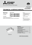
System remote controller PAC-SF44SRA
INSTRUCTION BOOK
Carefully read this book before use. It is recommended to safe keep this book for future reference.
ANWEISUNGSHANDBUCH
Vor Benutzung der Anlage dieses Buch sorgfältig durchlesen. Es wird empfohlen, dieses Buch zum Nachschlagen an einem
sicheren Ort aufzubewahren.
MANUEL D'UTILISATION
Lire attentivement le présent manuel avant toute utilisation et le conserver dans un endroit sûr pour pouvoir le consulter
ultérieurement.
LIBRO DE INSTRUCCIONES
Lea cuidadosamente este libro antes de usar el temporizador. Le recomendamos que guarde el libro en lugar seguro en previsión
de consultas Futuras.
LIBRETTO ISTRUZIONI
Leggere attentamente questo libretto prima dell'uso. Si raccomanda di tenerlo in un luogo sicuro per ogni futura necessitá.
INSTRUCTIEHANDLEIDING
Lees deze handleiding aandachtig door voordat u het apparaat in gebruik neemt. Het wordt aangeraden om deze handleiding
zorgvuldig te bewaren om later, indien nodig, te raadplegen.
CONTENTS
Page
1. Safety Precautions.....................................................................................................................2
2. Names and functions of each part .............................................................................................4
2-1. Appearance ......................................................................................................................4
2-2. Display sections................................................................................................................5
2-3. Operation section..............................................................................................................6
3. Operation ...................................................................................................................................7
3-1. Collective Setting/Monitor Screen, Group Setting/Monitor Screen ...................................7
3-2. Various setting methods ...................................................................................................8
4. Troubleshooting .......................................................................................................................15
4-1. When "COLLECTIVE ON/OFF LAMP" and "ERROR CODE" are flickering...................15
4-2. When "group operation status display" and "error code" are flickering ..........................15
5. When an external input signal is input .....................................................................................16
5-1. Emergency stop mode....................................................................................................16
5-2. Prohibit input mode.........................................................................................................16
6. Initial settings ...........................................................................................................................17
6-1. When this controller is master system ............................................................................17
6-1-1. Setting the group ..................................................................................................19
6-1-2. Setting the interlocked units .................................................................................23
6-1-3. Collective deletion ................................................................................................27
7. Error history monitor ................................................................................................................28
8. Setting the functions ................................................................................................................28
8-1. Using with master system controller ...............................................................................29
8-2. Setting local remote controller operation prohibit function from other controller.............29
8-3. Prohibiting operation of system controller other than this controller ...............................29
8-4. Changing set temperature display to "Fahrenheit display" .............................................29
9. Using the external input/output ................................................................................................30
9-1. External signal input function..........................................................................................30
9-2. External signal output functions......................................................................................31
10. System limits............................................................................................................................32
11. Specifications...........................................................................................................................33
11-1. Product functions ............................................................................................................33
11-2. Main specifications .........................................................................................................34
1. Safety Precautions
■ Always read these "Safety Precautions" before starting, and perform the installation work
correctly.
■ The dangers and degree that could occur if handling is mistaken are ranked with the following
symbols.
WARNING When fatalities or serious injuries could result if handling is mistaken.
CAUTION
When personal injury, or damage to house or assets could result if handling is mistaken.
■ After reading this manual store it in a safe place together with the installation manual for future
reference.
When changing users, always give this manual and the installation manual to the new user.
2
WARNING
■ Unit must not be installed by user.
Always contact your dealer or a specialist to install the unit. Improper installation by the user could result in
electric shocks or fires, etc.
■ Check the installation state.
Always check that the unit is installed on a solid place where it will not fall off.
■ Stop immediately when error occurs.
Continuing operation in an erroneous state could result in trouble, electric shocks or fires, etc. If any abnormality is sensed (burning smell, etc.), always stop the operation, turn the power switch OFF, and contact
your dealer.
■ Unit must not be moved and re-installed by user.
Improper installation by the user could result in electric shocks or fires, etc.
Always contact your dealer or a specialist when the unit must be moved.
■ Unit must not be disposed by user.
Contact your dealer when the unit must be disposed of.
■ Never modify or repair the unit.
Improper modifications or repairs could result in electric shocks or fires, etc. Always consult your dealer for
repairs.
■ Stop operation if operation is inhibited with an error display or if a fault occurs.
Continuing operation could result in fires or faults.
Contact your dealer.
CAUTION
■ Do not place hazardous objects near unit.
Do not install this unit where flammable gases could leak. If flammable gases leak and accumulate around
the unit, fires or explosions could result.
■ Do not wash this unit with water.
Washing the unit with water could result in electric shocks or faults.
■ Do not operate switches with wet hands.
Touching the unit with wet hands could result in electric shocks or faults.
■ Do not use for special applications.
This product is intended for use with the Mitsubishi Electric air conditioning control system. Do not use for
the control of other air conditioners or for other applications.
Failure to observe this could result in malfunctioning.
■ Do not spray insecticide or flammable sprays onto unit.
Do not place flammable sprays, etc., near the unit or spray these directly onto the unit.
Doing so could result in fires or explosions.
■ Do not use in special environments.
Using this product in environments containing a high level of oil (including machine oil), vapors or sulfuric
gases, etc., could result in a drop in performance or damage of parts.
■ Do not press switches with pointed objects.
Pressing with pointed objects could result in electric shocks or faults.
■ Observe the working temperature range.
Always observe the working temperature range. Serious faults could result if the unit is used outside the
working temperature range.
Refer to the specifications in the instruction manual for the working temperature range.
If not indicated in the instruction manual, the range is 0°C to 40°C (32°F to 104°F).
■ Do not pull or twist the transmission cables
Doing so could result in fires or faults.
■ Do not disassemble this unit.
Touching the internal PCBs, etc., is hazardous, and could result in fires or faults.
■ Do not wipe this unit with benzene, thinner or chemical rags.
Using these matters could result in discoloration or faults. If the unit is heavily dirtied, wipe off with a cloth
wetted in diluted neutral detergent, and then wipe again with a dry cloth.
3
GB
■ Check the rated power supply.
An incorrect power supply could result in fires or unit trouble.
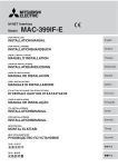
2. Names and functions of each part
2-1. Appearance
• This controller has two operation modes. One is the [Collective Setting/Monitor Screen] for making
operations and settings for all air conditioners, and the [Group Setting/Monitor Screen] for making
operations and settings for air conditioners in each group. The items that can be operated and set
from the screen differ for each mode. Refer to section 3. Operation (page 7) for details.
2
3
1
4
COL./GROUP
ON/OFF
MODE
GROUP
TEMP.
PROHIBIT
FAN SPEED
AIR DIRECTION
MODE
LOCK
LOUVER
VENTILATION
FILTER
SYSTEM
REMOTE CONTROLLER
PAC-SF44SRA
5
After turning the power on,wait until the "HO"or"H1"display goes out
(approximately 5 minutes)
1. COLLECTIVE/GROUP DISPLAY
Indicates which mode is selected:
COLLECTIVE: [Collective Setting/Monitor Screen]
GROUP: [Group Setting/Monitor Screen]
2. ON/OFF DISPLAY
[Collective Setting/Monitor Screen]
ON display: Displays when one or more groups are running.
(Does not display when only the interlocked units are running.)
OFF display: Displays when all groups are stopped.
(Displays even when the interlocked units are running.)
[Group Setting/Monitor Screen]
ON display: Displays when the selected group is running.
(Does not display when only the interlocked units are running.)
OFF display: Displays when the selected group is stopped.
(Displays even when the interlocked units are running.)
3. COLLECTIVE ON/OFF LAMP
ON: One or more group run
(Also ON when a sequential unit is running)
OFF: All groups stopped
Flicker: Malfunction occurred
4. COLLECTIVE ON/OFF SWITCH
If pressed when all groups are stopped, all groups will start running.
If pressed when one or more groups are running, all groups will stop.
If pressed when a registered air conditioner is malfunctioning, all groups will stop.
5. CAUTION
Remote control operations are not possible if "H0" or "H1" is displayed while the power is ON.
(Approx. five minutes.)
4
2-2. Display sections
GB
1. CENTRALIZED DISPLAY
This appears when operations from another system controller are prohibited.
2. ON/OFF DISPLAY
The operation status of the displayed group or all groups is displayed.
3. OPERATION MODE DISPLAY
The current operation mode is displayed.
4. GROUP NUMBER DISPLAY
The group number selected on the Group Setting/Monitor Screen is displayed.
5. GROUP OPERATION STATUS DISPLAY
ON: Run
OFF: Stop
Flicker: Malfunction
6. SET TEMPERATURE DISPLAY
The selected set temperature is displayed.
7. AIR DIRECTION DISPLAY
The blow off air direction is indicated with the "s" mark.
8. FAN SPEED DISPLAY
The selected fan speed is displayed.
9. LOUVER DISPLAY
The operation of the swing louver is displayed. This does not appear when stopped.
10. VENTILATION DISPLAY
This appears during ventilation operation.
11. PROHIBIT DISPLAY
This appears when operation of the local remote controller is prohibited by this controller.
12. MODE LOCK DISPLAY
This appears when switching to a specific operation mode is limited.
13. FILTER SIGN DISPLAY
This flickers when the filter’s periodic cleaning interval is reached.
14.
DISPLAY
This appears while the power is ON.
15. ERROR CODE DISPLAY
This flickers and displays an error code (4-digit) when an error is generated.
Examples of actual displays on each unit's Group Setting/Monitor Screen.
5
2-3. Operation section
9
1. ON/OFF SWITCH
When the [Collective Setting/Monitor Screen] is displayed, all groups can be collectively started
and stopped.
When the [Group Setting/Monitor Screen] is displayed, the selected group can be started and
stopped.
2. COL./GROUP SWITCH
Press this switch to switch between the [Collective Setting/Monitor Screen] and [Group
Setting/Monitor Screen].
3. GROUP SWITCH
Press this to call the required group screen when making various settings. (This can be used
only on the [Group Setting/Monitor Screen].)
4. MODE SWITCH
Use this switch to switch between cooling, dry, ventilation, automatic and heating modes.
For the LOSSNAY, use this to switch between automatic ventilation, normal ventilation and
heat exchanger ventilation.
5. FAN SPEED SWITCH
Use this switch to change the fan speed.
6. LOUVER SWITCH
Use this switch to set the air direction to left or right, or to stop.
7. TEMP. SWITCH
Use this switch to set the room temperature in 1(33.8)deg increments.
8. PROHIBIT SWITCH
Use this switch to prohibit operations with the local remote controller. The items that can be
prohibited are on/off, operation mode, set temperature and filter reset. (This can be operated
only when the controller is set to operation prohibit transmission valid.)
9. MODE LOCK SWITCH
Use this switch to limit switching of the controllers and local remote controller's operation
modes according to the season.
10. FILTER SWITCH
Press this switch to reset the filter sign.
11. AIR DIRECTION SWITCH
Press this switch to adjust the air direction up and down.
12. VENTILATION SWITCH
Use this switch to change the interlocked unit's ON/OFF mode and fan speed.
6
3. Operation
3-1. Collective Setting/Monitor Screen, Group Setting/Monitor Screen
• [Collective Setting/Monitor Screen]
• All groups controlled by this controller can be operated collectively.
• When any of the following operation switches is pressed for more than two seconds, each
default value will appear, and all air conditioners will be set with the next operation.
MODE, FAN SPEED, TEMP., AIR DIRECTION, LOUVER
GB
• The operation details will turn OFF if there is no operation for ten minutes.
• [Group Setting/Monitor Screen]
• Various operations can be performed for the selected group.
• When the COLLECTIVE ON/OFF switch is pressed, all groups will turn ON or OFF.
• If there is no operation for ten minutes, the [Collective Setting/Monitor Screen] will appear.
[Collective Setting/Monitor Screen]
[Group Setting/Monitor Screen]
Switches when the COL./GROUP switch
is pressed.
1. Some functions may not be operable depending on the air conditioner model.
2. Refer to "3-2. Various setting methods" on page 8 for more details.
7
3-2. Various setting methods
(1) ON/OFF
[Collective Setting/Monitor Screen]
1. The air conditioners and LOSSNAY for all groups will either turn ON or OFF when the
ON/OFF switch is pressed.
2. Pressing the COLLECTIVE ON/OFF switch has the same effect as pressing the ON/OFF
switch.
[Group Setting/Monitor Screen]
1. The air conditioner or LOSSNAY for the selected group will either turn ON or OFF when the
ON/OFF switch is pressed.
2. When the COLLECTIVE ON/OFF switch is pressed, the air conditioners and LOSSNAY for
all groups will turn ON or OFF.
If ON/OFF with other system controller's has been prohibited, the ON/OFF and
COLLECTIVE ON/OFF switches will not function. [- CENTRALIZED -] will flicker
if operated when prohibited.
(2) Operation mode
[Collective Setting/Monitor Screen]
1. Each time the MODE switch is pressed, the mode will change in the order of
AUTO
BY-PASS
HEATEX.
No display
(COOL)
(DRY)
(FAN)
EXCHANGE
(AUTO) (HEAT) (AUTO VENT) (NORMAL VENT) (HEATVENT)
If any of the above modes is not available in the registered unit, the operation mode will not
display.
Even if the operation mode is set collectively, the mode will not be set in a group that does not
have that operation mode.
[Group Setting/Monitor Screen]
1. Each time the MODE switch is pressed, the
mode will change in the order shown on the right.
(COOL)
(DRY)
(FAN)
(AUTO)
(HEAT)
The modes shown in brackets are not displayed if the indoor units registered in each group are
not provided with that operation mode.
In groups controlling LOSSNAY units, the mode
will change in the order shown on the right each
time the MODE switch is pressed.
AUTO
BY-PASS
HEATEX.
(AUTO VENT)
(NORMAL VENT)
(HEAT EXCHANGE
VENT)
1. If the operation changeover operation has been prohibited with another system
controller, the MODE switch will not function. [- CENTRALIZED -] will appear if
operated when prohibited.
2. If changeover to a mode is limited by this controller and another controller, that mode
will not display.
(Refer to (9) Operation mode changeover limit.)
8
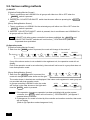
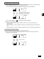
(3) Fan speed adjustment
[Collective Setting/Monitor Screen]
1. The display will change as shown on the right each time
the FAN SPEED switch is pressed.
2-step model
[Group Setting/Monitor Screen]
3-step model
4-step model
GB
When executed collectively, the fan speed
will be set in "four steps" regardless of the
model.
1. Each time the FAN SPEED switch is pressed, the display will change as shown on the right
from the currently displayed fan speed state.
Changeover of the fan speed differs according to the model being controlled.
The fan speed cannot be changed for models that do not have fan speed adjustment
provided in the indoor unit.
(“
” will flicker if operated.)
(4) Temperature adjustment
[Collective Setting/Monitor Screen]
1. When the TEMP.
or
switch is pressed once, 19°C (66.2°F) will appear on the
screen. The set temperature will change in 1 (33.8) deg increments each time the switch is
pressed.
If the switch is held down, the temperature will change continuously in 1 (33.8) deg
increments.
The temperature adjustment range for the collective setting is 19 to 28°C (66.2 to 82.4°F) for
all operation modes.
Air conditioner
Medium temperature air conditioner
The room temperature cannot be adjusted Cool/Dry 19 to 30 C/66.2 to 86 F 14 to 30 C/57.2 to 86 F
when controlling only the LOSSNAY.
Heat
17 to 28 C/62.6 to 82.4 F 14 (17) to 28 C/57.2 (62.6) to 82.4 F
o
o
o
o
o
o
o
o
o
o
o
o
Auto (cool/heat) 19 to 28 C/66.2 to 82.4 F 14 (17) to 28 C/57.2 (62.6) to 82.4 F
* The temperature adjustment cannot be set for fan operation.
[Group Setting/Monitor Screen]
1. The set temperature will change in 1(33.8)deg increments each time the TEMP.
switch is pressed.
or
If the switch is held down, the temperature will change continuously in 1(33.8)deg increments.
The room temperature adjustment range differs according to the air conditioner being
controlled. The room temperature cannot be changed for groups controlling only LOSSNAY.
([TEMP] and [°C] will flicker if operated.)
If adjustment of the room temperature has been prohibited with another system controller,
the TEMP.
and
switches will not function. [- CENTRALIZED -] will flicker if
operated when prohibited.
9
(5) LOUVER [Collective Setting/Monitor Screen, Group Setting/Monitor Screen]
1. Start/stop will be repeated each time the LOUVER switch is pressed, and the display will
change as shown below.
1. When operating the louvers collectively, “LOUVER ON” will appear regardless of the
model.
2. If the indoor unit in the group setting is not provided with the louver operation, "
"
will flicker.
(6) Air Direction
[Collective Setting/Monitor Screen]
1. The display will change as shown below each time the AIR DIRECTION switch is pressed.
When the wind direction is changed collectively, the vane permitted operation and swing
permitted operation are used regardless of the model. The air direction cannot be changed
when controlling only the LOSSNAY.
[Group Setting/Monitor Screen]
1. Each time the AIR DIRECTION
switch is pressed, the display will
change as shown on the right
from the currently displayed air
direction state.
The air direction changeover operation will differ according to the model being controlled.
The air direction cannot be changed for groups controlling only the LOSSNAY, and for
models that do not have a vane. (
will flicker if operated.)
(7) Interlock unit ON/OFF
[Collective Setting/Monitor Screen]
1. The display will change as shown below each time the VENTILATION switch is pressed.
No display
(OFF)
When starting and stopping interlocked units collectively, "INTERLOCK UNIT ON" will turn ON
regardless of the presence of interlocked units.
Interlocked units cannot be started or stopped when controlling only independent indoor units
or independent LOSSNAY units.
[Group Setting/Monitor Screen]
1. Each time the VENTILATION switch is pressed, the display will change as shown below
from the currently displayed interlocked unit ON/OFF state.
No display
(OFF)
The interlocked unit cannot be started or stopped if the group does not have interlocked
units. (
will flicker if operated.)
10
(8) Local remote controller operation prohibit setting
[Collective Setting/Monitor Screen]
1. Operations with all local remote controllers controlled with this controller can be prohibited.
[Group Setting/Monitor Screen]
1. Operations with the local remote controller for the selected group can be prohibited.
When this controller's SW3-5 operation prohibit range setting changeover has been set
to "ON (including system controller)", operations of the other system controllers can be
prohibited.
1. When the PROHIBIT switch is pressed, [ PROHIBIT , ON/OFF, MODE, TEMP., FILTER ]
will appear. Items that have already been prohibited will turn ON, and the permitted items will
flicker. All items will flicker on the [Collective Setting/Monitor Screen].
If the group is controlling LOSSNAY, [MODE, TEMP. ] will not appear.
2. Set the items to be prohibited or permitted with local remote controller operations.
• To prohibit or permit ON/OFF operations
:
Press the ON/OFF switch. The ON/OFF display will change when pressed.
• To prohibit or permit operation mode changeover
:
Press the MODE switch. The "MODE" display will change when pressed.
• To prohibit or permit room temperature adjustment
Press the TEMP.
or
:
switch.
The "TEMP" display will change when pressed.
• To prohibit or permit filter resetting operations
:
Press the FILTER switch. The "FILTER" display will change when pressed.
[Changes in display of each item] Flicker (Not set) → ON (Prohibit) → OFF (Permit)
When each item's switch is pressed, the related display will change as shown above from the
current display state.
[Meaning of displays]
Display
ON
ON/OFF Local remote controller ON/OFF operation prohibited
OFF or flickering (*1)
Local remote controller ON/OFF operation permitted
MODE
Local remote controller operation mode changeover prohibited
Local remote controller operation mode changeover permitted
TEMP.
Local remote controller room temperature adjustment prohibited
Local remote controller room temperature adjustment permitted
FILTER Local remote controller filter resetting prohibited
Local remote controller filter resetting permitted
3. The prohibited or permitted item will be set when the PROHIBIT switch is pressed, and local
remote controller operation of the items that are ON will be prohibited. The operation will be
permitted if the item is OFF or flickering (not set).
(*1) On the [Collective Setting/Monitor Screen], if all four items are flickering in step 3 above (nothing is
being operated), it does not mean that all operations are permitted. Instead this means that the previous settings will be applied.
1. This function can be set only when this controller's SW-4 operation prohibit setting
changeover is set to "ON (Permit)". Settings cannot be made when set to prohibited.
If the function is used when the setting is prohibited, [- CENTRALIZED -], PROHIBIT ,
ON/OFF, MODE, TEMP., FILTER] will flicker.
2. The operation mode changeover and room temperature adjustment operations cannot be prohibited for LOSSNAY groups.
11
GB
Setting method: Set on the [Collective Setting/Monitor Screen] or [Group Setting/Monitor Screen].
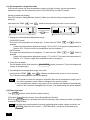
(9) Operation mode changeover limit (season changing)
Changeover to specific operation modes with this controller or the local remote controller for all
groups can be limited.
For example, the mode selection can be limited according to the season.
Cooling mode limit (winter), heating mode limit (summer), cooling + heating mode limit (between
seasons)
Setting methods: Set with the [Collective Setting/Monitor screen] or [Group Setting/Monitor screen].
1. Hold down the MODE LOCK switch for two or more seconds.
2. When the MODE LOCK switch is pressed next, the mode to be prohibited will light in the
following order.
No display
(no limits)
MODE LOCK
+
NO COOL
MODE LOCK
+
NO HEAT
MODE LOCK
+
NO COOL HEAT
When “NO COOL” is selected
: The cooling, dry or automatic modes cannot be selected
with the MODE switch.
When “NO HEAT” is selected
: The heating or automatic modes cannot be selected
with the MODE switch.
When “NO COOL HEAT” is selected : The cooling, dry, heating or automatic modes cannot be
selected with the MODE switch. (Only fan can be used.)
When no display (no limits) is selected : The limits will be cancelled.
1. This function can be used only when SW3-8 is set to ON.
2. Note that this function cannot be used with some indoor units. In this case,
changeover of the operation mode cannot be limited with the local remote controller.
(10) Time setting mode
• The current time of the system controller or remote controller, having a time setting function,
can be set collectively. (There are some remote controllers that cannot be set. This controller
does not have a clock function.)
[Setting method and display] Set the time from the Collective Setting/Monitor Screen.
Hold down the GROUP
12
and FILTER switches simultaneously for two or more seconds.
1. Selecting the setting item
Select the setting item with the GROUP
switches.
• Day setting
: GROUP
• Time setting
: TEMP.
/
/
/
switches or the TEMP.
/
switches
switches
GB
2. Setting the day (Select day setting in step 1.)
The day setting No. displayed at the group No. display section will change each time the
GROUP
switch is pressed.
“SU, MO, TU, WE, TH, FR, SA” will appear at the group operation status display section according to the day setting No.
01: Sunday (SU), 02: Monday (MO), 03: Tuesday (TU), 04: Wednesday (WE), 05: Thursday (TH),
06: Friday (FR), 07: Saturday (SA)
• The displays will change in reverse when the GROUP
switch is pressed.
3. Setting the time (Select time setting in step 1.)
• The time setting will advance in one-minute increments on the error code display section each
time the TEMP.
switch is pressed. If the switch is held down, the time advance method
will change in the order of one-minute increments, ten-minute increments and one-hour
increments.
• The set time will return in one-minute increments each time the TEMP.
switch is
pressed. If the switch is held down, the time return method will change in the order of
one-minute increments, ten-minute increments and one-hour increments.
4. Fixing the setting
The set details will be fixed when the FAN SPEED switch is pressed.
(The day setting No. and time setting display will change to stable lights.)
When the FAN SPEED switch is pressed again, each remote control’s time will be set. (The
clock mark “
” will disappear.)
• The seconds are reset to zero when the FAN SPEED switch is pressed.
5. Cancelling the time setting
Hold down the GROUP
and FILTER switches for two or more seconds.
• The setting screen will return to the Collective Setting/Monitor Screen.
• The details set before the setting was fixed will be erased.
If no operations are made on this screen for ten minutes, the display will automatically
switch to the Collective Setting/Monitor screen. (The details being set will be deleted.)
13
(11) Set temperature range limit mode
If the remote control has a set temperature range limit mode function, the set temperature
adjustment range can be collectively set for the [COOL/DRY] and [HEAT] modes.
[Setting method and display]
Use the [Collective Setting/Monitor Screen]. (Make sure that all units are stopped before
starting.)
Hold down the TEMP
and
switches simultaneously for two or more seconds.
Change by pressing
the MODE switch.
Temperature selection for cooling/dry mode
Temperature selection for heating mode
1. Setting the set temperature adjustment range
[COOL/DRY] mode
The lower limit temperature will change by 1°C each time the TEMP
or
switch is
pressed.
[Lower limit temperature adjustment range]: 19°C to 30°C (The upper limit temperature is
fixed to 30°C. Only the lower limit temperature can be changed.)
[HEAT] mode
The upper limit temperature will change by 1°C each time the TEMP
or
switch is
pressed.
[Upper limit temperature adjustment range]: 17°C to 28°C (The lower limit temperature is
fixed to 17°C. Only the upper limit temperature can be changed.)
2. Fixing the set details
The set details will be fixed when the FAN SPEED switch is pressed. (The mode display will
change to a stable light.)
3. Cancelling the set temperature range limit mode
Hold down the TEMP
and
switches simultaneously for two or more seconds.
The Collective Setting/Monitor Screen will appear.
1. The operation mode will change to ventilation after the set temperature range limit is
set, so the operation mode must be changed to the previous mode.
2. If no operations are made on this screen for ten minutes, the display will automatically
switch to the Collective Setting/Monitor Screen. (The details being set will be deleted.)
(12) Filter sign reset
The FILTER flickers, when the filter needs cleaning.
[Collective Setting/Monitor Screen, Group Setting/Monitor Screen]
When the FILTER switch is pressed two times successively after cleaning the filter, the display
turned OFF and is reset.
If the filter sign reset operation has been prohibited with another system controller, the
FILTER switch will not function. [- CENTRALIZED -] will flicker if operated when
prohibited.
14
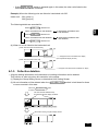
4. Troubleshooting
4-1. When "COLLECTIVE ON/OFF LAMP" and "ERROR
CODE" are flickering
• The air conditioner is stopped because a problem has occurred and operation cannot be
continued.
• Check the address of the unit where the error is occurring and the error code, and call your
nearest MITSUBISHI ELECTRIC supplier or dealer.
The COLLECTIVE ON/OFF lamp flickers.
The address No. of the faulty unit and the attributes
alternately flicker and display.
The error code flickers and displays. (4-digit)
The operation status for each group containing
the faulty unit is displayed.
1. If an error occurs while the [Collective Setting/Monitor Screen] is displayed, the details of the
error for the group containing the first problem will appear.
2. If the error occurs while the [Group Setting/Monitor Screen] is displayed, the error will display
only when the currently selected group has the error.
3. If an error occurs in several groups, the operation status display for each group having an
error will flicker, so check the details of the error with "Checking errors in a different group".
• Checking errors in a different group
Press the GROUP switch to select the group with the error, and check the details of the
error.
1. If an error occurs in a group other than that displayed on the [Group Setting/Monitor
Screen], the COLLECTIVE ON/OFF lamp and the group operation status of the
group with the error will flicker.
2. The details of past errors can be confirmed. Refer to section "7. Error history monitor"
for details.
4-2. When "group operation status display" and "error code"
are flickering
• The air conditioner will continue operation, but there may be a problem.
• Check the error code and contact your dealer or service center.
The error code flickers. (4-digit)
The operation status for each group containing
the faulty unit is displayed.
15
GB
The group No. of the faulty unit flickers.
1. If an error occurs while the [Collective Setting/Monitor Screen] is displayed, the details of the
error for the group containing the first problem will appear.
2. If the error occurs while the [Group Setting/Monitor Screen] is displayed, the error will display
only when the currently selected group has the error.
3. If an error occurs in several groups, the operation status display for each group having an
error will flicker, so check the details of the error with "Checking errors in a different group".
If the error is occurring in a group other than that displayed on the [Group
Setting/Monitor Screen], only the group operation status display for the group with the
error will flicker.
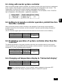
5. When an external input signal is input
5-1. Emergency stop mode
• If an emergency stop input is input in the external input interface, all air conditioners and
LOSSNAY units being controlled will turn OFF.
This controller, slave system controller and local remote control operations will be prohibited
until the emergency stop input is cancelled.
• When the emergency stop is cancelled, the state before it was input will be recovered.
(Excluding the ON/OFF state.)
(The external input adapter used for emergency stop input is not enclosed with this controller.)
[-CENTRALIZED-] will flicker.
OFF will flicker.
5-2. Prohibit input mode
• When prohibit input is input to the external input interface, the on/off, operation mode, setting
temperature and filter reset operations using the manual remote control being controlled will be
prohibited.
• When permit is input, the local remote control operation prohibit will be cancelled.
PROHIBIT flickers only for the
[Collective Setting/Monitor screen].
16
6. Initial settings
• When connecting multiple system controllers, designate the system controller with many
functions as the "master", and set the system controllers with few functions as the "slaves".
(Refer to section 8. Setting the functions, "8-1 Using with master system controller" for details
on the "master/slave" settings.)
• If this controller is controlled by the master system controller, carry out the initial settings with
the master system controller. In this case, this controller will use the slave settings, and does
not require initial settings.
GB
6-1. When this controller is master system
The initial settings include the following items:
• Group setting • Interlocked unit setting • Collective deletion
Open the Initial Setting Mode Screen to make these settings.
(1) The following display will appear when the power to this controller is turned ON.
ON/OFF
(2) When group setting information is already set
During system startup communication,
"H1" will blink at the group No. display section
When system startup communication is completed,
the Group Setting/Monitor Screen will open.
(3) When there is no group setting information, or when changing the group setting
information:
Hold down the FILTER and LOUVER switches simultaneously for two or more
seconds while "H0" is flickering in step 1, or on the Group Setting/Monitor screen or
Collective Setting/Monitor screen. (When pressing the switches simultaneously, if the
LOUVER switch is pressed first, the Default Setting Mode screen will not open.)
When opening each screen from step 2, if there is an error in any group, the switch
operation will be invalid.
17
This controller's own address will flicker for two seconds.
Carry out steps 6-1-1 to 6-1-2 from the state shown above.
(4) Cancel the initial setting mode.
• After setting the group and the interlocked unit, hold down the FILTER and LOUVER
switches simultaneously for two or more seconds.
• Save the group setting information and interlocked unit setting information, etc., with this
step, and then carry out system startup communication. The Group Setting/Monitor Screen
will open when completed. (Refer to step (2))
Do not turn the power OFF during system startup communication (while "H1" is flickering).
(The group setting information, etc., will not be saved in the memory if the power is
turned OFF.)
18
6-1-1. Setting the group
• Register the indoor unit, LOSSNAY, slave system controller and local remote controller for
each group. (Register the LOSSNAY to be interlocked with the indoor unit using the
interlocked unit setting.)
• If the group setting information has already been set and no operations are made on this
screen for ten minutes, the display will automatically switch to the Collective Setting/Monitor
screen. (The details being set will be deleted.)
1. Select the group
Select the group in which the unit is to be registered.
GB
2. Select the unit
Select the unit, etc., to be registered in the group selected in step 1.
3. Registering the unit into a group
4. Deleting a unit from a group
5. Searching for registered units
Go to step 6-1 (4) or 6-1-2.
1. Select the group
(1) The group operation status display (( ) in following example) will move in order each time
the GROUP
switch is pressed, and the group No. display section will also change.
The display will move in reverse when the GROUP
switch is pressed.
(2) After the group is selected, if a unit is registered in the group the minimum address No. unit
will appear. The attributes for that group will appear after two seconds.
Displayed details
{
Set temperature display section ... Address No.
Group No. display section ............ Address No. attributes
19
Example) When groups 1 and 2 are not registered, and the address 005 indoor unit is registered
in group 3
2. Selecting the unit
(1) Select the unit to be registered in the group selected in step 1.
• The address No. at the set temperature display section will change in order each time the
TEMP.
switch is pressed. (If held down for three seconds or more, the skip function
will activate when carrying over.)
• The numbers will appear in reverse order when the TEMP.
Address No. setting range
Indoor unit, LOSSNAY
:
Local remote controller
:
101 to 200
Slave system controller
:
000, 201 to 250
switch is pressed.
001 to 050
Set temperature display section : Address No. will appear
(2) When registered unit is selected
• If the selected unit is already registered in any of the 50 groups controlled by this controller,
the following type of display will appear.
Example) When unit 011 is called out with group 3
Group operation status display flickers
This indicates that the unit is already
registered in "group 23"
20
3. Registering the unit into a group
(1) Register the unit selected in step 2 into a group.
• With the group No. and unit address selected in steps 1 and 2 displayed, press the
FAN SPEED switch.
• The registration process will be completed with this step.
• When correctly registered, an attribute such as "
registered, "
" will be displayed. If not correctly
" will flicker instead of the attribute.
GB
Attribute such as " " will appear when correctly registered.
Display the address
No. to be registered.
Registration complete screen
The address 006 indoor unit is registered in group 3
The attributes displayed for each unit when registered are as follow.
Indoor unit
: IC
LOSSNAY
: LC
Local remote controller: RC
System controller: SC
(2) Registering a separate unit
• When registering a separate unit into the same group, carry out steps 2 and 3.
• When registering a unit into a different group, carry out steps 1 to 3.
1. Units cannot be registered into the same group with the following combination.
• Indoor unit and LOSSNAY
When registration is attempted, these will not be correctly registered and "88" will
flicker on the screen.
2. If the indoor unit, LOSSNAY and local remote controller are already registered in
another group, they cannot be registered in a different group. However, the slave
system controller can also be registered in a different group.
21
4. Deleting a unit from a group
(1) Using steps 1 and 2, call out the address No. of the unit to be deleted.
• When the FILTER switch is pressed twice in this state, the unit registered in the group
will be deleted.
Press FILTER switch twice.
The attribute display will turn OFF and “- -” will
appear when normally completed.
5. Searching for registered units
The address numbers of all units registered in a group can be checked.
(1) Using step 1, select the group to be searched.
(2) The address numbers of the registered units will appear in order of smallest number each
time the MODE LOCK switch is pressed.
Press MODE LOCK switch once
Press MODE LOCK switch once
Press MODE LOCK switch once
For SC, if the system controller is also registered in another
group, that group operation status display will also flicker.
(3) If a single unit is not registered, "---" will display.
22
6-1-2. Setting the interlocked units
• Set that units interlocked with each group can be run in linked.
• Set the interlocked units after setting the group.
The interlocked units cannot be set until the units are registered in the group in which interlocked
units are to be set.
1. Calling the Interlocked Unit Setting Screen
2. Selecting the group No.
GB
Select the group in which the interlocked units are to be registered.
This same step is used for searching and deleting.
3. Calling the registration unit
4. Selecting the interlocked unit's address No.
5. Registering the interlocked unit
6. Cancelling the interlock setting
7. Searching for interlocked units
Go to step 6-1. (4) or 6-1-1.
• When registering the interlocked unit, if an indoor unit and interlocked unit in a certain
group are to be linked, always register the indoor unit with the smallest address No.
in the group for interlocking. If the unit is not registered for interlocking, the
interlocked unit cannot be operated (ventilation changeover) with the local remote
controller.
• If there are several indoor units to be linked with the interlocked unit, register all
indoor units for interlocking.
1. Calling the Interlocked Unit Setting Screen
(1) Open the Interlocked Unit Setting Screen from the Group Setting Screen.
Press the COL./GROUP switch.
"--" or attributes are displayed after two seconds.
"---" or unit address is displayed.
The screens will alternate between
the Group Setting Screen and Interlocked Unit
Setting Screen each time the COL./GROUP switch
is pressed.
"--" or attributes are displayed after two seconds.
Interlocked unit address No. display section
"---" or unit address is displayed.
23
2. Selecting the group No.
(1) Call the Group No.
• Call the group No. in which the interlocked unit is to be registered.
Use the same operations as section 6-1-1. (1) Selecting the group.
• Select the group with the GROUP
and
switches.
(2) When the group is selected, the corresponding group No. will appear at the group No. display
section.
(3) After the group is selected, if there are registered units, the registered unit with the smallest
address No. will appear.
Displayed details
{
Set temperature display section ... Address No.
Group No. display section ............ Address No. attributes
Example) When group 1 is not registered, and the address 003 indoor unit is registered in group 2.
"--" appears after two seconds
"---" displays as no unit
is registered in group 1
Press
once
" " attributes display after two seconds
3. Calling the registration unit
Call the address No. of the indoor unit to be registered as the interlocked unit by pressing the
COLLECTIVE ON/OFF switch.
4. Selecting the interlocked unit's address No.
(1) Set the address No. of the interlocked unit to be registered with the indoor unit selected in
step 3.
• With the indoor unit from step 3 selected, press the TEMP.
switch.
• The address No. of the interlocked unit will change in the following order each time the
switch is pressed. (If held down for three seconds or more, the skip function will activate
when carrying over.)
• The address numbers will appear in reverse order when the TEMP.
pressed.
switch is
The attribute display turns OFF
when the switch is pressed.
Set to the address No. of the interlocked
unit to be registered.
24
5. Registering the interlocked unit
(1) When the FAN SPEED switch is pressed in the state shown in step 4, the interlocked unit
will be registered as interlocked to the displayed indoor unit.
• The following type of display will appear when the unit is correctly registered.
GB
The address No. of the set indoor unit,
the address No. of the interlocked unit,
and the attributes alternately display.
If not correctly registered, "
" will flicker instead of the attribute.
(2) Set the next interlocked unit
• Carry out steps 3 and 5 to register a different indoor unit in the same group to the
interlocked unit.
• Carry out steps 2, 3 and 5 to register an indoor unit in a different group to the interlocked
unit.
• Carry out steps 2, 3, 4 and 5 to register a different indoor unit to a different interlocked unit.
6. Cancelling the interlock setting
Cancel the interlock setting of the indoor unit and interlocked unit.
(1) Call out the screen displayed after the interlocked unit is set, or the screen on which the
interlocked unit was searched.
Displays alternately
25
(2) The interlock setting will be cancelled when the FILTER switch is pressed twice in this state.
The attribute display will change to "--"
when completed normally.
Displays alternately
7. Searching for interlocked units
Search to find which indoor unit the interlocked unit is linked to.
(1) To search from interlocked unit
Carry out step 4 to display the address No. of the interlocked unit for which the setting is to be
confirmed.
• Select the interlocked unit with the TEMP.
and
switchs.
Display the address No. of the interlocked
unit to be searched for.
Either the indoor unit's address No. or
"---" can be displayed at the set temperature display section.
Press the MODE LOCK switch in the above state.
(2) To search from indoor unit
Using steps 2 and 3, display the address No. of the indoor unit for which the interlock setting is
to be confirmed.
• Select the indoor unit with the group selection
switches or COLLECTIVE
ON/OFF switch.
Display the address No. of the
indoor unit to be confirmed.
“---” will appear at the error code
display section.
Press the MODE LOCK switch in the above state.
(3) When interlocked unit is set
The address No. and attribute of the linked indoor unit will appear.
Displays alternately
The interlocked unit's address No. and attribute will appear.
26
• If the MODE LOCK switch is pressed again in this state, the other units linked to the
interlocked unit can be confirmed.
Example) When the following units are linked to interlocked unit 030.
Indoor unit ... 001 (group 1)
002 (group 2)
The following details are searched for.
Indoor unit address 001 and attributes
GB
Press MODE LOCK switch once.
Interlocked unit address 030
and attributes
Press MODE LOCK switch once.
Indoor unit address 002 and attributes
Interlocked unit address 030
and attributes
Press MODE LOCK switch once.
(4) When no unit is linked to the interlocked unit
[When searched from interlocked unit]
[When searched from indoor unit]
“—” will appear at the unit address No. display
(set temperature display section)
“—” will appear at the interlocked unit address No. display
6-1-3. Collective deletion
• All group setting information and interlocked unit setting information can be deleted.
This function is valid only when this controller is the master.
(1) Display the Group Setting Screen or Interlocked Unit Setting Screen.
(2) All set information will be deleted when the AIR DIRECTION switch is held down for three
or more seconds in this state.
Hold down AIR DIRECTION switch
for three or more seconds
The COLLECTIVE ON/OFF lamp
and GROUP BLOCK display will flicker.
"H0" flickers at the group No. display section.
27
7. Error history monitor
• Up to 50 past errors can be saved in the memory.
If more than 50 errors occurred, the oldest errors will be deleted sequentially.
The errors described in section '4-2 When "group operation status display" and "error code" are
flickering', are not saved in the memory.
[Display and monitor methods]
Operate from the Collective Setting/Monitor Screen or from the error display.
1. The error history will appear when the PROHIBIT and LOUVER switchs are held down
simultaneously for two or more seconds.
(When pressing the switches simultaneously, if the LOUVER switch is pressed first, the
Error History will not open.)
2. The last error history will appear each time the GROUP
switch is pressed.
3. The next error history will appear each time the GROUP
switch is pressed.
History No. is displayed in group block display section
Selected history No. flickers
The faulty attributes are displayed in group No. display section
1 2 3 4 5 6 7 8 9 10
Newest error
10
20
30
40
"Inspecting" appears
Oldest error
Error code is displayed
The faulty address is displayed in set
temperature display section
The number of saved history items is indicated
[Deleting the error history]
1. Display the error history to be deleted, and press the FILTER switch twice. The selected
error history will be deleted.
2. All error histories will be deleted when the AIR DIRECTION switch is held down for three or
more seconds.
[Cancelling the error history monitor]
1. Hold down the PROHIBIT and LOUVER switches simultaneously for two or more seconds.
2. The MONITOR screen will return to the Collective Setting/Monitor Screen or Error Display
Screen.
If no operations are made on this screen for ten minutes, the display will automatically
switch to the Collective Setting/Monitor screen.
8. Setting the functions
SW3
ON
OFF
1 2 3 4 5 6 7 8
Remote controller main unit
28
8-1. Using with master system controller
When connecting multiple system controllers, the system controller with many functions is designated
as the "master", and the system controllers with few functions are designated as the "slaves". The
"master/slave" functions of the system controller used together are as follows.
The functions have a priority in order of G50 (MJ-103MTRA) > PAC-SF44SRA > PAC-YT34STA >
PAC-YT40ANRA > PAC-SC30GRA > LMAP02-E (LMAP03U).
Switch setting Factory setting
SW3-1 : OFF
OFF
SW3-1 : ON
GB
Setting details
Master side
Slave side
8-2. Setting local remote controller operation prohibit function
from this controller
When connecting several system controllers, and setting the "local remote control operation
prohibit" function from this controller, set this controller's "operation prohibit setting changeover"
to "ON (permit)".
(The 9-1 External signal input function cannot be used when this function is set to disable.)
Setting details
Disable
Enable
Switch setting Factory setting
SW3-4 : OFF
OFF
SW3-4 : ON
8-3. Prohibiting operation of system controller other than this
controller
To prohibit the operation of a system controller other than this controller when the local remote
control operation is set to prohibit with this controller, set this controller's "operation prohibit range
changeover" to "ON (including system controller)."
Setting details
Switch setting Factory setting
Only local remote control
SW3-5 : OFF
OFF
Including system controller SW3-5 : ON
8-4. Changing set temperature display to "Fahrenheit display"
Setting details
Switch setting Factory setting
Celsius display
: oC SW3-6 : OFF
OFF
o
Fahrenheit display : F SW3-6 : ON
After changing the switch 3 1,4 to 6 ON/OFF status, always turn the power OFF.
The function will change only after the power is turned OFF and ON.
29
9. Using the external input/output
9-1. External signal input function
• In order to use external signal input, use the 5-wire cable for external input that comes with the unit.
(1) External input
By using an external no voltage contact signal, it is possible to send Emergency stop/Normal,
ON/OFF or Prohibit/Permit local remote controller operation commands to all units being
controlled. (This is selected by the SW3 setting. SW3 is mounted on the main unit board.)
SW3
External input signal functions
No.
Input state
2
3
_
1
Do not use external input.
OFF
OFF
2
Change between emergency stop/normal.
During an emergency stop, all units will be stopped, and all operations using this
controller, other system controllers and the local remote control will be prohibited.
OFF
ON
Level input
3
Set ON/OFF.
All units will turn ON/OFF according to the input state.
ON
OFF
Level input
4
Set ON/OFF and prohibit/permit .
All units will turn ON/OFF and all local remote controller ON/OFF operations will be
prohibited according to the input state. Operation with this controller will be enabled.
When prohibit is input, the local remote control’s ON/OFF, operation mode, set
temperature and filter reset operation will be prohibited. This controller can be operated.
ON
ON
Pulse input
(0.5sec or
more)
(2) Level signal and pulse signal
(A) Level signal
Contact ON
Contact OFF
Contact ON
Contact OFF
(B) Pulse signal
(Example) Case of ON/OFF signal
OFF
Normal
ON
OFF
Signal 1
ON
Contact ON
Contact OFF
Signal 2
OFF
Contact ON
Contact OFF
0.5sec or more
0.5sec or more
Emergency
Normal
stop
OFF
ON
OFF
*Prohibit/Permit is same.
1. Only emergency stop can be used when SW3-4 "operation prohibit setting
changeover" is set to "OFF (disabled)".
2. If the level input emergency stop and ON/OFF are set, operation of the other system
controllers will be prohibited even if SW3-5 "operation prohibit range changeover" is
set to "OFF (only local remote control)".
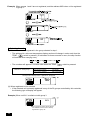
(3) External input specifications
Level signal for Emergency
CN2 Lead wires (5-wires) stop/Normal
Pulse signal for ON/OFF,
Level signal for ON/OFF Prohibit/Permit
Green
Emergency stop/Normal input
ON/OFF input
No. 2
Yellow
Not used
Not used
No. 3
Orange
Not used
Not used
No. 4
Red
Not used
No. 5
Brown
No. 1
30
Not used
Common 0V
ON input
OFF input
Prohibit local remote controller
operation input
Permit local remote controller
operation input
(A) Level signal cases
External input
Contact operation
OFF ON
ON
OFF
Operation status
Emergency stop/Normal
Normal
ON/OFF
Emergency stop
Emergency stop
Normal
OFF
ON
ON
OFF
(B) Pulse signal cases
2. When manual remote control is set to prohibit, the on/off, operation mode, set temperature
and filter reset operations using the manual remote control will be prohibited.
3. Set the pulse duration (contact ON period) to 0.5 sec or more.
1. Level signal
• All operations using this controller and the local remote control are prohibited when
the emergency stop contact is ON.
2. Pulse signal
• All units will continue running even if the ON signal is input. (This also applies to OFF,
prohibit and permit.)
9-2. External signal output functions
• In order to use external signal output, use the 4 wires external output cable that comes with the
unit.
(1) External output
In the case when one or more units are running “ON” and an error occurs in one or more units,
a signal indicating that an error is occurring is output.
(2) External output specifications
CN3
Lead wires (4wires, with black tube)
No.1
Yellow
No.2
Orange
No.3
Red
No.4
Brown
Details of each terminal
ON/OFF
Error/Normal
1. “ON ” is output even when there is “Error ”.
31
GB
1. Operation will start with the operation signal input, and will stop with the stop signal input.
(This applies to prohibit and permit.)
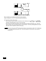
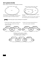
10. System limits
Master system controller and slave system controller
This controller's control range
Master system controller control range
This controller's control range
This controller's control range
Unit
Unit
Unit
When the system contains only this controller.
This controller is set as the master system controller.
In this case, the group is set with this controller.
When this controller is controlled by another system
controller.
This controller is set as the slave system controller. In
this case, the group is not set with this controller.
The following types of group settings are not possible.
• Control by the slave system controller of a
unit not within the control of the master
system controller.
Master system
controller
Group
• Control of a common group with two or
more master system controllers.
Slave system
controller
Group
Master system
controller 1
Group
Group
Master system
controller 2
Group
• Setting of a slave system controller
exceeding the control range of two or
more master system controllers.
Master system
controller 1
Group
32
Slave system
controller
Group
Master system
controller 2
Group
Group
Group
11. Specifications
11-1. Product functions
• This controller can control up to 50 air conditioners and LOSSNAY. This controller has the
following functions.
<List of system remote controller functions>
Details
ON/OFF
ON/OFF operations can be carried out collectively or for each group.
Operation mode
The air conditioner can be set to cool, dry, fan, auto or heat
collectively or for each group. The LOSSNAY can be set to normal
ventilation, heat exchange ventilation or automatic ventilation.
Fan speed
The fan speed can be selected collectively or for each group.
(The set fan speeds differ according to the model.)
The temperature can be set collectively or for each group.
Set temperature range
Cool/Dry: 19 to 30oC
Heat:
Set temperature
14 to 30oC
<66.2 to 86oF>
<57.2 to 86oF>
17 to 28oC
14(17) to 28oC
<62.6 to 82.4oF>
<57.2(62.6) to 82.4oF>
Automatic:19 to 28oC
<66.2 to 82.4oF>
o
14(17) to 28 C
o
<57.2(62.6) to 82.4 F>
(The set temperature display can be changed to "Fahrenheit display" with the switches.)
Operation
The values in parentheses are for when using the medium temperature unit.
The set temperature range will differ according to the model.
Normal
Louver
The louver can be started or stopped collectively or for each group.
Air direction/swing
The Air direction can be set to four steps up and down or to swinging collectively or for each group.
Interlocked unit ON/OFF
functions
Local remote controller
operation prohibit
Operation mode
changeover limitation
(season changing)(*1)
Filter reset
The local remote controller's ON/OFF, operation mode, set
temperature and filter reset operations can be prohibited collectively
or for each group.
(Only when this controller is set to operation prohibit transmission
valid.)
Changing of this controller's and the local remote control's operation
mode can be limited collectively or for each group.
Cooling mode limit (winter), heating mode limit (summer),
cooling/heating mode limit (between seasons)
The filter sign can be reset after the filter is cleaned collectively or for each group.
External input
Emergency stop, ON/OFF, and prohibit/permit can be set collectively from an external source.
Collective run
Displayed with the COLLECTIVE ON/OFF lamp.
Group operation status
Filter sign
Monitor
When using an interlocked unit (LOSSNAY), ON (high/low) or OFF
can be set collectively or for each group.
The ON/OFF, operation mode, wind speed, set temperature, wind direction,
and interlocked unit ON/OFF status are displayed for each group.
The filter cleaning period is indicated for each group.
Local operation prohibit
Details prohibited by this controller or by other controllers are displayed.
Error
The address of the faulty unit and the error code are displayed on the LCD.
External output
The ON/OFF and error occurrence signals can be output collectively to an external source.
Error history monitor
Up to 50 past errors can be saved and checked. (50 errors that have occurred last.)
(*1) Only groups in the free plan indoor units (Type C and following models) can be limited.
33
GB
Function
<List of system remote controller functions>
Function
Details
Group setting
Set the unit (indoor unit, LOSSNAY remote controller, slave system controller)
group.
Interlocked unit setting
Set interlocking with the LOSSNAY and indoor unit.
Master system controller
/slave system controller (*1)
Set the system controller as the master or slave.
Operation
Prohibit range
Initial
setting System (*3) Prohibit transmission/reception
functions
"Celsius/Fahrenheit" display
System remote
controller own address
Set whether to prohibit operations for the remote control with this
controller.
Set the set temperature display to a Celsius or Fahrenheit display.
Set the system remote controller's own address (Refer to the
Installation Manual.)
Set temperature
range limit mode
The current time can be set collectively for system controllers and remote
controls provided with the time setting function.
The set temperature range can be set collectively for remote controls
provided with the set temperature range limit mode function.
Indoor units, LOSSNAY
Maximum 50 units (Maximum 50 groups)
Number of indoor units and
LOSSNAY
0 to 16 units (The indoor unit and LOSSNAY cannot be registered
in the same group.)
Time setting (*4)
Others
Set whether to prohibit operation with the local remote controller using this
controller or with another controller.
System
Number of
Number of local remote
limits
registered units controllers in one group
Number of system controllers
controlling one group (*2)
Number of indoor units
linked with one LOSSNAY
0 to 2 units
0 to 4 units (Includes the number of local remote controllers for one
group.) 0 to 3 units in group having one local remote controller
0 to 16
(*1) Refer to page 33.
(*2) This controller (system remote controller) is one of the system controllers.
(*3) Refer to page 29.
(*4) This controller does not have a clock function.
11-2. Main specifications
Item
Power source
Power consumption
Working environment conditions
Weight
Outline dimensions
34
Details
30VDC (supplied from indoor unit or power feed unit for transmission line (type: PAC-SC34KUA).
1W
Temperature 0 to 40oC / 32 to 104oF, humidity 30 to 90%RH (with no dew condensation)
0.2o
(H x W x D) 120 x 130 x18[mm] / 4 3/4 x 5 1/16 x 3/4[in]
HEAD OFFICE: MITSUBISHI DENKI BLDG., 2-2-3, MARUNOUCHI, CHIYODA-KU, TOKYO 100-8310, JAPAN
WT03804X01