1
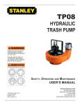
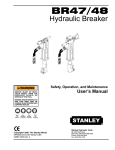
BR87
HYDRAULIC BREAKER
WARNING
WARNING
To avoid serious injury or death
SAFETY, OPERATION AND MAINTENANCE
USER'S MANUAL
© Stanley Hydraulic Tools 2006
OPS/MAINT USA / CE
Printed in U.S.A.
65778 1/2006 ver 3
Stanley Hydraulic Tools
3810 SE Naef Road
Milwaukie OR 97267-5698
503-659-5660
FAX 503-652-1780
www.stanley-hydraulic-tools.com
TABLE OF CONTENTS
CERTIFICATE OF CONFORMITY ........................................................................................................................................4
SAFETY SYMBOLS ..............................................................................................................................................................5
SAFETY PRECAUTIONS......................................................................................................................................................6
TOOL STICKERS & TAGS ....................................................................................................................................................7
HYDRAULIC HOSE REQUIREMENTS.................................................................................................................................8
HTMA REQUIREMENTS.......................................................................................................................................................9
OPERATION........................................................................................................................................................................10
PRE-OPERATION PROCEDURES.....................................................................................................................................10
CHECK POWER SOURCE .................................................................................................................................................10
INSTALL TOOL BIT .............................................................................................................................................................10
CONNECT HOSES .............................................................................................................................................................10
OPERATION PROCEDURES .............................................................................................................................................10
COLD WEATHER OPERATION ..........................................................................................................................................10
EQUIPMENT PROTECTION & CARE ................................................................................................................................ 11
TROUBLESHOOTING ........................................................................................................................................................12
CHARGING THE ACCUMULATOR .....................................................................................................................................13
ACCUMULATOR TESTING PROCEDURE ........................................................................................................................13
ACCUMULATOR CHARGING .............................................................................................................................................13
GENERAL SERVICE NOTES .............................................................................................................................................13
UNDERWATER MODEL PREVENTATIVE MAINTENANCE ..............................................................................................14
SPECIFICATIONS ...............................................................................................................................................................15
ACCESSORIES ..................................................................................................................................................................15
SERVICE TOOLS ................................................................................................................................................................15
BR87 PARTS ILLUSTRATION ............................................................................................................................................16
BR87 PARTS LIST ..............................................................................................................................................................18
WARRANTY ........................................................................................................................................................................19
SERVICING THE STANLEY HYDRAULIC breaker. This manual contains safety, operation, and routine
maintenance instructions. Stanley Hydraulic Tools recommends that servicing of hydraulic tools, other
than routine maintenance, must be performed by an authorized and certified dealer. Please read the following warning.
WARNING
SERIOUS INJURY OR DEATH COULD RESULT FROM THE
IMPROPER REPAIR OR SERVICE OF THIS TOOL.
REPAIRS AND / OR SERVICE TO THIS TOOL MUST ONLY BE
DONE BY AN AUTHORIZED AND CERTIFIED DEALER.
For the nearest authorized and certified dealer, call Stanley Hydraulic Tools at the number listed on the
back of this manual and ask for a Customer Service Representative.
3
CERTIFICATE OF CONFORMITY
CERTIFICATE OF CONFORMITY
Hydraulic Tools
______________________________________________________________________
I, the undersigned:
Winterling, David
Surname and First names
Hereby certify that the construction plant or equipment specified hereunder:
1. Manufacturer: Stanley Hydraulic Tools, 3810 Naef Road, Milwaukie, Oregon USA
2. Representative in the Union: Stanley Svenska AB, Box 9054, 400 92 Göteborg, SWEDEN
3. Category: Hydraulic Hand Held Concrete Breaker
4. Make:
Stanley Hydraulic Tools
5. Type:
BR8713201
6. Type serial number of equipment: ALL
7. Year of manufacture: Beginning 2002
Has been manufactured in conformity with the provisions of the Machinery Directive 98/37/EC
Harmonized standard applied:
EN 792-4
We also declare that it meets the specification of Noise Directive 2000/14/EC, measured in accordance to
the Conformity Evaluation Method set out in Annex VI para. 5 and evaluated during production as in Annex
VI para. 6, 2nd procedure.
8. Noise related value: 38 kg
9. Measured sound power on equipment representative of this type: 110 LwA
10. Guaranteed sound power level for this equipment: 111 LwA
11. Notified body for EC directive 2000/14/EC:
0404
SMP Svensk Maskinprovning AB
Fyrisborgsgatan 3
754 50 Uppsala, SWEDEN
12. Special Provisions: None
Issued at Stanley Hydraulic Tools, Milwaukie, Oregon USA
Date: 8/21/02
Signature
Position: Engineering Manager
P/N 52575 Rev.2, 1/17/06
4
SAFETY SYMBOLS
Safety symbols and signal words, as shown below, are used to emphasize all operator, maintenance and repair
actions which, if not strictly followed, could result in a life-threatening situation, bodily injury or damage to equipment.
This is the safety alert symbol. It is used to alert you to potential personal
injury hazards. Obey all safety messages that follow this symbol to avoid
possible injury or death.
WARNING
This safety alert and signal word indicate an imminently hazardous situation which, if not avoided, will result in death or serious injury.
WARNING
This safety alert and signal word indicate a potentially hazardous situation
which, if not avoided, could result in death or serious injury.
CAUTION
This safety alert and signal word indicate a potentially hazardous situation
which, if not avoided, may result in minor or moderate injury.
CAUTION
This signal word indicates a potentially hazardous situation which, if not
avoided, may result in property damage.
NOTICE
This signal word indicates a situation which, if not avoided, will result in
damage to the equipment.
IMPORTANT
This signal word indicates a situation which, if not avoided, may result in
damage to the equipment.
Always observe safety symbols. They are included for your safety and for the protection of the tool.
LOCAL SAFETY REGULATIONS
Enter any local safety regulations here. Keep these instructions in an area accessible to the operator and maintenance personnel.
5
SAFETY PRECAUTIONS
WARNING
To avoid serious injury or death
Tool operators and maintenance personnel must always comply with the safety
precautions given in this manual and on the stickers and tags attached to the tool
and hose.
These safety precautions are given for your safety. Review them carefully before
operating the tool and before performing general maintenance or repairs.
Supervising personnel should develop additional precautions relating to the specific
work area and local safety regulations. If so, place the added precautions in the
space provided in this manual.
The BR87 Hydraulic Breaker will provide safe and dependable service if operated
in accordance with the instructions given in this manual. Read and understand this
manual and any stickers and tags attached to the tool and hoses before operation.
Failure to do so could result in personal injury or equipment damage.
• Operator must start in a work area without bystanders. The operator must be familiar with all prohibited work areas such
as excessive slopes and dangerous terrain conditions.
• Establish a training program for all operators to ensure safe operation.
• Do not operate the tool unless thoroughly trained or under the supervision of an instructor.
• Always wear safety equipment such as goggles, ear, head protection, and safety shoes at all times when operating the
tool.
• Do not inspect or clean the tool while the hydraulic power source is connected. Accidental engagement of the tool can
cause serious injury.
• Supply hoses must have a minimum working pressure rating of 2500 psi/175 bar.
• Be sure all hose connections are tight.
• The hydraulic circuit control valve must be in the “OFF” position when coupling or uncoupling the tool. Wipe all couplers
clean before connecting. Use only lint-free cloths. Failure to do so may result in damage to the quick couplers and cause
overheating of the hydraulic system.
• Do not operate the tool at oil temperatures above 140°F/60°C. Operation at higher oil temperatures can cause operator
discomfort and may damage the tool.
• Do not operate a damaged, improperly adjusted, or incompletely assembled tool.
• Do not weld, cut with an acetylene torch, or hardface the tool bit.
• To avoid personal injury or equipment damage, all tool repair, maintenance and service must only be performed by authorized and properly trained personnel.
• Do not exceed the rated limits of the tool or use the tool for applications beyond its design capacity.
• Always keep critical tool markings, such as lables and warning stickers legible.
• Always replace parts with replacement parts recommended by Stanley Hydraulic Tools.
• Check fastener tightness often and before each use daily.
• Never operate the tool if you cannot be sure that underground utilities are not present.
• Do not wear loose fitting clothing when operating the tool.
6
TOOL STICKERS & TAGS
WARNING
To avoid serious injury or death
11207
Circuit Type C Decal
28409
Composite Decal
11208
Hex Shank Decal
Lwa
111
28322
CE Decal
10180
Caution Decal
66656
Sound Level Decal
Stanley Hydraulic tools
Division of the Stanley Works
3810 SE Naef Road
Milwaukie, OR 97267
28376
Stanley Decal
28381
BR87 Name Tag
(Models BR8713201 & BR8717201 Only)
D A N G E R
1. FAILURE TO USE HYDRAULIC HOSE LABELED AND CERTIFIED
AS NON-CONDUCTIVE WHEN USING HYDRAULIC TOOLS
ON OR NEAR ELECTRICAL LINES MAY RESULT IN DEATH
OR SERIOUS INJURY.
07892
BR87 Name Decal
BEFORE USING HOSE LABELED AND CERTIFIED AS NONCONDUCTIVE ON OR NEAR ELECTRIC LINES BE SURE THE
HOSE IS MAINTAINED AS NON-CONDUCTIVE. THE HOSE
SHOULD BE REGULARLY TESTED FOR ELECTRIC CURRENT
LEAKAGE IN ACCORDANCE WITH YOUR SAFETY DEPARTMENT INSTRUCTIONS.
2. A HYDRAULIC LEAK OR BURST MAY CAUSE OIL INJECTION
INTO THE BODY OR CAUSE OTHER SEVERE PERSONAL
INJURY.
A
The safety tag (p/n
15875) at right is attached
to the tool when shipped
from the factory. Read
and understand the safety
instructions listed on this
tag before removal. We
suggest you retain this tag
and attach it to the tool
when not in use.
DO NOT EXCEED SPECIFIED FLOW AND PRESSURE FOR
THIS TOOL. EXCESS FLOW OR PRESSURE MAY CAUSE A
LEAK OR BURST.
B DO NOT EXCEED RATED WORKING PRESSURE OF HYDRAU
LIC HOSE USED WITH THIS
TOOL. EXCESS PRESSURE MAY
CAUSE A LEAK OR BURST.
C CHECK TOOL HOSE COUPLERS AND CONNECTORS DAILY
FOR LEAKS. DO NOT FEEL FOR LEAKS WITH YOUR
D A N G E R
D DO NOT LIFT OR CARRY TOOL BY THE HOSES. DO
NOT ABUSE HOSE. DO NOT USE KINKED, TORN OR
DAMAGED HOSE.
3. MAKE SURE HYDRAULIC HOSES ARE PROPERLY CONNECTED
TO THE TOOL BEFORE PRESSURING SYSTEM. SYSTEM
PRESSURE HOSE MUST ALWAYS BE CONNECTED TO TOOL
“IN” PORT. SYSTEM RETURN HOSE MUST ALWAYS BE
CONNECTED TO TOOL “OUT” PORT. REVERSING CONNECTIONS MAY CAUSE REVERSE TOOL OPERATION WHICH CAN
RESULT IN SEVERE PERSONAL INJURY.
4. DO NOT CONNECT OPEN-CENTER TOOLS TO CLOSED-CENTER HYDRAULIC SYSTEMS. THIS MAY RESULT IN LOSS OF
OTHER HYDRAULIC FUNCTIONS POWERED BY THE SAME
SYSTEM AND/OR SEVERE PERSONAL INJURY.
5. BYSTANDERS MAY BE INJURED IN YOUR WORK AREA. KEEP
BYSTANDERS CLEAR OF YOUR WORK AREA.
6. WEAR HEARING, EYE, FOOT, HAND AND HEAD PROTECTION.
7. TO AVOID PERSONAL INJURY OR EQUIPMENT DAMAGE, ALL
TOOL REPAIR MAINTENANCE AND SERVICE MUST ONLY BE
PERFORMED BY AUTHORIZED AND PROPERLY TRAINED
PERSONNEL.
IMPORTANT
IMPORTANT
READ OPERATION MANUAL AND
SAFETY INSTRUCTIONS FOR THIS
TOOL BEFORE USING IT.
READ OPERATION MANUAL AND
SAFETY INSTRUCTIONS FOR THIS
TOOL BEFORE USING IT.
USE ONLY PARTS AND REPAIR
PROCEDURES APPROVED BY
STANLEY AND DESCRIBED IN THE OPERATION MANUAL.
USE ONLY PARTS AND REPAIR
PROCEDURES APPROVED BY
STANLEY AND DESCRIBED IN THE OPERATION MANUAL.
TAG TO BE REMOVED ONLY BY
TOOL OPERATOR.
TAG TO BE REMOVED ONLY BY
TOOL OPERATOR.
SEE OTHER SIDE
SEE OTHER SIDE
SAFETY TAG P/N 15875
7
(shown smaller then actual size)
HYDRAULIC HOSE REQUIREMENTS
HOSE TYPES
Hydraulic hose types authorized for use with Stanley Hydraulic Tools are as follows:
Certified non-conductive
Wire-braided (conductive)
Fabric-braided (not certified or labeled non-conductive)
Hose listed above is the only hose authorized for use near electrical conductors.
Hoses and listed above are conductive and must never be used near electrical conductors.
HOSE SAFETY TAGS
To help ensure your safety, the following DANGER tags are attached to all hose purchased from Stanley Hydraulic Tools. DO NOT REMOVE THESE TAGS.
If the information on a tag is illegible because of wear or damage, replace the tag immediately. A new tag may be
obtained from your Stanley Distributor.
D A N G E R
D A N G E R
1 FAILURE TO USE HYDRAULIC HOSE LABELED AND CERTIFIED AS NON-CONDUCTIVE
WHEN USING HYDRAULIC TOOLS ON OR NEAR ELECTRIC LINES MAYRESULT IN DEATH
OR SERIOUS INJURY.
FOR PROPER AND SAFE OPERATION MAKE SURE THAT YOU HAVE BEEN PROPERLY
TRAINED IN CORRECT PROCEDURES REQUIRED FOR WORK ON OR AROUND
ELECTRIC LINES.
3. DO NOT EXCEED HOSE WORKING PRESSURE OR ABUSE HOSE. IMPROPER USE OR
HANDLING OF HOSE COULD RESULT IN BURST OR OTHER HOSE FAILURE. KEEP
HOSE AS FAR AWAY AS POSSIBLE FROM BODY AND DO NOT PERMIT DIRECT CONTACT
DURING USE. CONTACT AT THE BURST CAN CAUSE BODILY INJECTION AND SEVERE
PERSONAL INJURY.
4. HANDLE AND ROUTE HOSE CAREFULLY TO AVOID KINKING, ABRASION, CUTTING, OR
CONTACT WITH HIGH TEMPERATURE SURFACES. DO NOT USE IF KINKED. DO NOT USE
HOSE TO PULL OR LIFT TOOLS, POWER UNITS, ETC.
2. BEFORE USING HYDRAULIC HOSE LABELED AND CERTIFIED AS NON-CONDUCTIVE ON
OR NEAR ELECTRIC LINES. WIPE THE ENTIRE LENGTH OF THE HOSE AND FITTING
WITH A CLEAN DRY ABSORBENT CLOTH TO REMOVE DIRT AND MOSISTURE AND TEST
HOSE FOR MAXIMUM ALLOWABLE CURRENT LEAKAGE IN ACCORDANCE WITH SAFETY
DEPARTMENT INSTRUCTIONS.
5. CHECK ENTIRE HOSE FOR CUTS CRACKS LEAKS ABRASIONS, BULGES, OR DAMAGE TO
COUPLINGS IF ANY OF THESE CONDITIONS EXIST, REPLACE THE HOSE IMMEDIATELY.
NEVER USE TAPE OR ANY DEVICE TO ATTEMPT TO MEND THE HOSE.
6. AFTER EACH USE STORE IN A CLEAN DRY AREA.
SIDE 1
3
DO NOT REMOVE THIS TAG
DO NOT REMOVE THIS TAG
THE TAG SHOWN BELOW IS ATTACHED TO “CERTIFIED NON-CONDUCTIVE” HOSE
SIDE 2
(shown smaller than actual size)
D A N G E R
D A N G E R
1 DO NOT USE THIS HYDRAULIC HOSE ON OR NEAR ELECTRIC LINES. THIS HOSE IS
NOT LABELED OR CERTIFIED AS NON-CONDUCTIVE. USING THIS HOSE ON OR NEAR
ELECTRICAL LINES MAY RESULT IN DEATH OR SERIOUS INJURY.
5. CHECK ENTIRE HOSE FOR CUTS CRACKS LEAKS ABRASIONS, BULGES, OR DAMAGE TO
COUPLINGS IF ANY OF THESE CONDITIONS EXIST, REPLACE THE HOSE IMMEDIATELY.
NEVER USE TAPE OR ANY DEVICE TO ATTEMPT TO MEND THE HOSE.
2. FOR PROPER AND SAFE OPERATION MAKE SURE THAT YOU HAVE BEEN PROPERLY
TRAINED IN CORRECT PROCEDURES REQUIRED FOR WORK ON OR AROUND
ELECTRIC LINES.
6. AFTER EACH USE STORE IN A CLEAN DRY AREA.
3. DO NOT EXCEED HOSE WORKING PRESSURE OR ABUSE HOSE. IMPROPER USE OR
HANDLING OF HOSE COULD RESULT IN BURST OR OTHER HOSE FAILURE. KEEP
HOSE AS FAR AWAY AS POSSIBLE FROM BODY AND DO NOT PERMIT DIRECT CONTACT
DURING USE. CONTACT AT THE BURST CAN CAUSE BODILY INJECTION AND SEVERE
PERSONAL INJURY.
4. HANDLE AND ROUTE HOSE CAREFULLY TO AVOID KINKING, CUTTING, OR CONTACT
WITH HIGH TEMPERATURE SURFACES. DO NOT USE IF KINKED. DO NOT USE HOSE TO
PULL OR LIFT TOOLS, POWER UNITS, ETC.
DO NOT REMOVE THIS TAG
DO NOT REMOVE THIS TAG
THE TAG SHOWN BELOW IS ATTACHED TO “CONDUCTIVE” HOSE.
SEE OTHER SIDE
SIDE 1
SIDE 2
(shown smaller than actual size)
HOSE PRESSURE RATING
The rated working pressure of the hydraulic hose must be equal to or higher than the relief valve setting on the
hydraulic system.
8
HTMA REQUIREMENTS
TOOL CATEGORY
HYDRAULIC SYSTEM
REQUIREMENTS
FLOW RATE
TYPE 1
TYPE II
7-9 gpm
(26-34 lpm)
2000 psi
(138 bar)
TYPE III
TOOL OPERATING PRESSURE
(at the power supply outlet)
4-6 gpm
(15-23 lpm)
2000 psi
(138 bar)
SYSTEM RELIEF VALVE SETTING
(at the power supply outlet)
2100-2250 psi 2100-2250 psi 2100-2250 psi 2200-2300 psi
(145-155 bar) (145-155 bar) (145-155 bar) (152-159 bar)
MAXIMUM BACK PRESSURE
(at tool end of the return hose)
250 psi
(17 bar)
Measured at a max. fluid viscosity of:
(at min. operating temperature)
400 ssu*
400 ssu*
400 ssu*
400 ssu*
(82 centistokes) (82 centistokes) (82 centistokes) (82 centistokes)
TEMPERATURE
Sufficient heat rejection capacity
to limit max. fluid temperature to:
(at max. expected ambient temperature)
140° F
(60° C)
140° F
(60° C)
140° F
(60° C)
140° F
(60° C)
Min. cooling capacity
at a temperature difference of
between ambient and fluid temps
3 hp
(2.24 kW)
40° F
(22° C)
5 hp
(3.73 kW)
40° F
(22° C)
7 hp
(4.47 kW)
40° F
(22° C)
6 hp
(5.22 kW)
40° F
(22° C)
250 psi
(17 bar)
11-13 gpm
(42-49 lpm)
2000 psi
(138 bar)
TYPE RR
250 psi
(17 bar)
9-10.5 gpm
(34-40 lpm)
2000 psi
(138 bar)
250 psi
(17 bar)
NOTE:
Do not operate the tool at oil temperatures above 140° F (60° C). Operation at higher temperatures can cause operator
discomfort at the tool.
FILTER
25 microns
Min. full-flow filtration
30 gpm
Sized for flow of at least:
(114 lpm)
(For cold temp. startup and max. dirt-holding capacity)
25 microns
30 gpm
(114 lpm)
HYDRAULIC FLUID
Petroleum based
(premium grade, anti-wear, non-conductive)
VISCOSITY
(at min. and max. operating temps)
100-400 ssu* 100-400 ssu*
(20-82 centistokes)
100-400 ssu*
25 microns
30 gpm
(114 lpm)
25 microns
30 gpm
(114 lpm)
100-400 ssu*
NOTE:
When choosing hydraulic fluid, the expected oil temperature extremes that will be experienced in service determine the
most suitable temperature viscosity characteristics. Hydraulic fluids with a viscosity index over 140 will meet the requirements over a wide range of operating temperatures.
*SSU = Saybolt Seconds Universal
NOTE:
These are general hydraulic system requirements. See tool Specification page for tool specific requirements.
9
OPERATION
The recommended hose size is .500 inch/12 mm I.D. up to
50 ft/15 m long and .625 inch/16 mm I.D. minimum up to
100 ft/30 m.
3. Place the bit firmly on the surface to be broken.
4. Squeeze the trigger to start the breaker. Adequate
down pressure is very important. When the tool bit breaks
through the obstruction or becomes bound, release the trigger and reposition the tool bit.
PRE-OPERATION PROCEDURES
CHECK POWER SOURCE
NOTE:
Partially depressing the trigger allows the tool to run at
slow speed. Slow-speed operation permits easier starting of the tool bit into the work surface.
1. Using a calibrated flowmeter and pressure gauge, check
that the hydraulic power source develops a flow of 7-9
gpm/26-34 lpm at 1500-2000 psi/105-140 bar.
2. Make certain the hydraulic power source is equipped
with a relief valve set to open at 2100-2250 psi/145-155 bar
maximum.
INSTALL TOOL BIT
5. To start, break an opening (hole) in the center of the
surface. After making a hole, break portions of the material
into the original opening. For best productivity, the breaking
should be done around the original hole.
The size of the broken material will vary with the strength
and thickness of the base material and the amount of any
reinforcement wire or rebar.
1. Rotate the latch on the breaker foot downward (pointing
away from the tool).
2. Insert the tool bit into the foot and pull the latch up to lock
the tool bit in place.
Harder material or more reinforcing wire or rebar will require taking smaller bites. To determine the most effective
bite, start with 2 in. / 50 mm or smaller bites.
CONNECT HOSES
1. Wipe all hose couplers with a clean, lint-free cloth before
making connections.
Bites can then be gradually increased until the broken
piece becomes too large, requiring increased time to break
off the piece.
2. Connect the hoses from the hydraulic power source to
the tool fittings or quick disconnects. It is a good practice
to connect return hoses first and disconnect them last to
minimize or avoid trapped pressure within the tool.
Sticking of the tool bit occurs when too large a bite is being
taken and the tool bit hammers into the material without
the material fracturing. This causes the tool bit to become
trapped in the surrounding material.
3. Observe flow indicators stamped on hose couplers to
ensure that fluid flow is in the proper direction. The female
coupler on the tool hose is the inlet coupler.
6. The underwater model requires preventative maintenance after each day’s use underwater and prior to being
placed in storage. See the General Service Notes section
in this manual for this maintenance procedure.
4. Move the hydraulic circuit control valve to the ON position to operate the tool.
COLD WEATHER OPERATION
NOTE:
If uncoupled hoses are left in the sun, pressure increase within the hoses may make them difficult to
connect. When possible, connect the free ends of the
hoses together.
If the breaker is to be used during cold weather, preheat the
hydraulic fluid at low engine speed. When using the normally recommended fluid, fluid temperature should be at or
above 50° F/10° C (400 ssu/82 centistokes) before use.
Damage to the hydraulic system or breaker can result from
use with fluid that is too viscous or thick.
OPERATION PROCEDURES
1. Observe all safety precautions.
2. Install the appropriate tool bit for the job.
10
EQUIPMENT PROTECTION & CARE
NOTICE
In addition to the Safety
Precautions found in this
manual, observe the
following for equipment
protection and care.
• Make sure all couplers are wiped clean before connection.
• The hydraulic circuit control valve must be in the “OFF” position when coupling or uncoupling
hydraulic tools. Failure to do so may result in damage to the quick couples and cause overheating
of the hydraulic system.
• Always store the tool in a clean dry space, safe from damage or pilferage.
• Make sure the circuit PRESSURE hose (with male quick disconnect) is connected to the “IN” port.
The circuit RETURN hose (with female quick disconnect) is connected to the opposite port. Do not
reverse circuit flow. This can cause damage to internal seals.
• Always replace hoses, couplings and other parts with replacement parts recommended by Stanley
Hydraulic Tools. Supply hoses must have a minimum working pressure rating of 2500 psi/172 bar.
• Do not exceed the rated flow (see Specifications in this manual for correct flow rate and
model number). Rapid failure of the internal seals may result.
• Always keep critical tool markings, such as warning stickers and tags legible.
• Do not force a small breaker to do the job of a large breaker.
• Keep tool bit sharp for maximum breaker performance. Make sure that tool bits are not chipped or
rounded on the striking end.
• Never operate a breaker without a tool bit or without holding it against the work surface. This puts
excessive strain on the breaker foot.
• Tool repair should be performed by experienced personnel only.
• Make certain that the recommended relief valves are installed in the pressure side of the system.
• Do not use the tool for applications for which it was not intended.
11
TROUBLESHOOTING
PROBLEM
Tool does not run.
Tool does not hit effectively.
Tool operates slow.
Tool gets hot.
CAUSE
REMEDY
Power unit not functioning.
Check power unit for proper flow and pressure (7-9
gpm/26-34 lpm, 1500-2000 psi/105-140 bar.
Couplers or hoses blocked.
Remove restriction.
Pressure and return line hoses reversed
at ports.
Be sure hoses are connected to their proper ports.
Mechanical failure of piston or automatic
valve.
Disassemble breaker and inpsect for damaged parts.
Power unit not functioning.
Check power unit for proper flow and pressure (7-9
gpm/26-34 lpm, 1500-2000 psi/105-140 bar.
Couplers or hoses blocked.
Remove restriction.
Low accumulator charge (pressure hose
will pulse more than normal).
Recharge accumulator. Replace diaphragm if charge
loss continues.
Fluid too hot (above 140°F/60°C).
Provide cooler to maintain proper fluid temperature
(130°F/55°C).
The collar support is not sliding freely in
the foot bore.
Remove, clean and replace as required. Make sure
hex bushing is in the proper location.
Low gpm supply from power unit.
Check power unit for proper flow (7-9 gpm/
26-34 lpm).
High backpressure.
Check hydraulic system for excessive backpressure
(over 250 psi/17 bar).
Couplers or hoses blocked.
Remove restriction.
Orifice plug blocked.
Remove restriction.
Fluid too hot (above 140°F/60°C) or too
cold (below 60°F/16°C).
Check power unit for proper fluid temperature.
Bypass cooler to warm the fluid or provide cooler to
maintain proper temperature.
The collar support is not sliding freely in
the foot bore.
Remove, clean and replace as required. Make sure
hex bushing is in the proper location.
Relief valve set too low.
Adjust relief valve to 2100-2250 psi/145-155 bar.
Hot fluid going through tool.
Check power unit. Be sure flow rate is not too high
causing part of the fluid to go through the relief
valve. Provide cooler to maintain proper fluid temperature (140°F/60°C max).
Check the relief valve setting.
Eliminate flow control devices.
Fluid leakage on tool bit.
Lower piston seal failure.
Replace seal.
Fluid leakage through charge
valve cap.
Upper piston seal failure or accumulator
o-ring failure or accumulator charge loss
or failure.
Replace seals, recharge or replace accumulator
diaphragm.
Fluid leakage around trigger.
Valve spool seal failure.
Replace seals.
12
CHARGING THE ACCUMULATOR
ACCUMULATOR TESTING
PROCEDURE
3. Adjust the regulator to the charging pressure of 800
psi/55 bar.
To check or charge the accumulator the following equipment is required:
NOTE:
It may be necessary to set the gauge at 850-900 psi/59-62
bar to overcome any pressure drop through the charging system.
31254 Charge Kit: which includes the following.
• Accumulator Tester (Part Number 02835).
• Charging Assembly (Part Number 15304).
(p/n 15304 includes a liquid filled gauge with snub valve,
hose and fittings.)
4. Open the valve on the charging assembly hose.
5. When the accumulator is fully charged close the valve
on the charging assembly hose and remove the charging
assembly chuck from the accumulator tester or tool charging valve.
• NITROGEN bottle with an 1000 psi/70 bar minimum
charge. (Not included in 31254 Charge Kit.)
1. Remove the valve cap assembly from the breaker.
6. If the accumulator tester has been used, be sure to turn
the gauge-end fully counterclockwise before removing the
tester from the charging valve of the tool.
2. Remove the protective cap and loosen the 5/8-inch hex
locking nut on the tool charging valve 1-1/2 turns.
7. Tighten the 5/8-inch hex locking nut on the tool charging
valve and replace the protective cap.
3. Holding the chuck end of Accumulator Tester (Part Number 02835) turn the gauge fully counterclockwise to ensure
that the stem inside the chuck is completely retracted.
8. Replace the valve cap assembly.
4. Thread the tester onto the accumulator charging valve.
Do not advance the gauge-end into the chuck-end. Turn as
a unit. Seat the chuck on the accumulator charging valve
and hand tighten only.
GENERAL SERVICE NOTES
1. If the breaker is repainted after servicing, be sure to
mask off the vent in the valve cap assembly. Do not allow
paint to enter the IN and OUT ports or the bore of the foot
assembly.
5. Advance the valve stem of the tester by turning the
gauge-end clockwise until a pressure is read on the gauge
(charge pressure should be 700-900 psi/48-62 bar).
2. If the handle grips need to be replaced.
6. If pressure is OK unscrew the gauge-end from the chuck
to retract the stem, then unscrew the entire tester assembly from the accumulator charging valve. If pressure is
low, charge the accumulator as described in the following
paragraph.
a. Remove the old grips and clean the handle.
b. Wash the new grips and the handle clean and dry, simply
push or drive the grips on. DO NOT lubricate the parts. The
grips will not be secure on the handle if any grease or oil is
used.
7. Tighten the 5/8-inch hex locking nut on the tool charging
valve. Be careful not to overtighten. Install the protective
cap and valve cap assembly.
ACCUMULATOR CHARGING
1. Perform steps 1 through 4 of the accumulator testing
procedure above.
2. Connect the chuck of the charging assembly to the
charging valve on the accumulator tester or, if preferred,
remove the tester from the charging valve and connect the
charging assembly chuck directly to the charging valve.
13
CHARGING THE ACCUMULATOR
oil through the drive hex and side holes in the breaker foot
assembly to displace any remaining water in the lower
piston cavity.
UNDERWATER MODEL
PREVENTATIVE MAINTENANCE
2. Spray oil into the On/Off valve trigger slot area.
After each use, the movable portions of the tool that were
exposed to water should be flushed with a water displacing
oil such as WD40. Remove any remaining water and debris
as follows:
3. Dip or spray the entire tool.
4. Cycle the tool hydraulically several times before storing
away.
1.Turn the tool upside down (without the tool bit) and spray
14
SPECIFICATIONS
Pressure Range .......................................................................................................................... 1500-2000 psi/105-140 bar
Flow Range ............................................................................................................................................ 7-9 gpm / 26-34 lpm
Optimum Flow ................................................................................................................................................ 8 gpm / 30 lpm
Maximum Back Pressure ................................................................................................................................ 250 Psi/17 bar
Connect Size & Type .................................................................................................................3/8 in. Male Pipe Hose Ends
Weight ...............................................................................................................................................................80 lbs / 36 kg
Length ...............................................................................................................................................................27 in. / 68 cm
Width .................................................................................................................................................................16 in. / 40 cm
System Type ...................................................................................................................................... Open or Closed Center
HTMA Type II
Port Size .............................................................................................................................................................SAE 8 o-ring
Guaranteed Sound Power Level ............................................................................................................................... 111 dBA
Sound Pressure Level at Operator ............................................................................................................................102 dBA
Vibration Level ..................................................................................................................................................... 21.5 m/sec2
ACCESSORIES
1-1/8 in. Hex x 6 in. Shank
Moil Point, 14 in. Long UC ............................................................................................................................................. 02333
Chisel Point, 14 in. Long UC ......................................................................................................................................... 03990
3-inch Chisel, 14 in. Long UC ........................................................................................................................................ 02334
Clay Spade, 5-1/2 in. Blade ........................................................................................................................................... 02331
Asphalt Cutter, 5 in. Blade, 11 in. Long ......................................................................................................................... 02332
Asphalt Wedge .............................................................................................................................................................. 08106
Ground Rod Driver, 1-in. Rod ........................................................................................................................................ 04176
1-1/4 in. Hex x 6 in. Shank
Asphalt Cutter, 5 in. Blade, 11 in. Long UC ................................................................................................................... 02335
Moil Point, 14 in. Long UC ............................................................................................................................................. 02336
3-inch Chisel, 14 in. Long UC ........................................................................................................................................ 02337
1- inch Chisel, Heavy Duty, 14 in. Long UC .................................................................................................................. 02338
Ground Rod Driver, 1 in. Rod ........................................................................................................................................ 04367
Moil Point, Heavy Duty, 18 in. Long UC ........................................................................................................................ 04404
Clay Spade, 8 in./20 cm Blade ...................................................................................................................................... 04405
Asphalt Wedge .............................................................................................................................................................. 08119
Clay Spade, 5-1/2 in. Blade ........................................................................................................................................... 09262
Test Equipment
Accumulator Tester ........................................................................................................................................................ 02835
Flow and Pressure Tester .............................................................................................................................................. 04182
Accumulator Charge Kit (Inlcludes 02835 Tester, 15304 Accumulator Charge Assy and 372047 Box) ........................ 31254
Accumulator Charge Assy (Incl. Liquid Filled Gauge with Valve, Hose and Charge Fitting) ......................................... 15304
UC denotes dimension measured from bttom tip of tool to bottom surface of collar.
SERVICE TOOLS
O-Ring Tool Kit ............................................................................................................................................................. 04337
Seal Kit ......................................................................................................................................................................... 05485
Accumulator Disassembly Tool..................................................................................................................................... 05508
Accumulator cylinder Puller .......................................................................................................................................... 05640
Split Rings .................................................................................................................................................................... 04908
Flow Sleeve Installation Spacer ................................................................................................................................... 04909
Flow Sleeve Removal Tube .......................................................................................................................................... 04910
15
BR87 PARTS ILLUSTRATION
16
BR87 PARTS ILLUSTRATION
17
BR87 PARTS LIST
Item
No.
Part No.
Qty
Description
1
06185
11435
1
Handle Assy. (Incl. Item 35)
Breaker Handle (Trigger Lock Models Only)
2
04050
1
Valve Cap Assy.
3
04051
1
Item
No.
Part No.
Qty
42
01744
1
Spring
43
01745
08411
1
Detent, 1.000 OAL, (Serial No. 1707 and Below)
Detent, 1.250 OAL, (Serial No. 1708 and Above)
Charging Valve
44
01269
2
Rubber Sleeve, 1.000
04984
1
Stop Nut
Description
4
04052
1
O-Ring
45
5
04053
11434
1
Trigger
Trigger (Trigger Lock Models Only)
46
04985
2
Spring Washer
47
09546
2
Pigtail Hose Assy.
00844
1
48
05265
1
Flow Sleeve Housing
49
24666
1
Elastometric Spacer
51
07515
1
Spring
52
07517
07518
1
Hex Bushing, 1-1/8
Hex Bushing, 1-1/4
6
Spirol Pin
7
04054
3
O-Ring
8
22891
2
Spirol Pin, 3/16 x 1-5/8
9
04055
1
Washer
10
04056
1
Rod Wiper
11
00293
1
O-Ring
53
11614
1
Breaker Foot Assy.
12
01362
1
O-Ring
54
07522
1
Retaining Ring
13
04057
1
Bushing
55
08115
08116
1
Collar Support Assy. 1-1/8 w/Wear Rings
Collar Support Assy. 1-1/4 w/Wear Rings
56
07892
28381
1
Nameplate Decal
Nameplate Decal (BR8713201 & BR8717201 Only)
14
04058
1
Spring
15
04059
1
Accumulator Diaphragm
16
04060
1
Accumulator Cylinder
57
28322
1
CE Decal
17
05309
1
Accumulator Chamber Assy.
58
11207
1
Circuit Type “D” Decal
11208
1
Hex Shank Length Decal
06889
1
Accumulator Assembly
(Incl. Items 3, 7, 15 thru 19)
59
60
66656
1
Sound Power Level Decal
18
05301
1
Back-up Washer
61
28409
1
Composite Decal
19
05307
1
Cup Seal
62
---
-
No Item
20
04064
1
Washer
63
10180
1
Caution Decal
21
04065
1
Automatic Valve
64
01605
2
O-Ring (Incl. with Item 47)
03973
1
Flush Face Coupler, Male
03972
1
Flush Face Coupler, Female
24069
1
Coupler Set (Used on BR87130E and BR87120)
22
04066
1
Automatic Valve Body
65
23
04571
2
Push Pin, 3/16 x 1-1/4
66
24
04067
4
Push Pin, 5/16 x 2
25
04068
1
Flow Sleeve Tube
67
05464
1
Seal Insert
26
04069
1
Flow Sleeve
68
01003
1
Button
27
16812
1
Piston
69
11430
1
Spring
28
04071
4
Side Rod
70
11435
1
Handle
29
04075
4
Side Rod Nut
71
11431
1
Lock Pin
Roll Pin, 3/16 x 1-1/2
72
11432
1
Key
73
11434
1
Trigger
30
07890
1
31
34127
1
Cup Seal
32
04073
1
O-Ring
33
04074
1
Rod Wiper
Part No.
Qty
Description
34
04077
1
Valve Spool, OC
00293
1
O-Ring
35
02494
2
Handle Grip
00678
1
O-Ring
36
05465
1
Orifice Plug
01362
1
O-Ring
37
05466
05467
1
Foot Assy. 1-1/8 Hex (Incl. Items 31-33 & 38-46 and 67)
Foot Assy. 1-1/4 Hex (Incl. Items 31-33 & 38-46 and 67)
01605
2
O-Ring
38
05484
1
Foot Assy. (Incl. Items 33-67)
1
Easi-RideTM Foot Assy. 1-1/8 Hex
(Incl. Items 33, 40 thru 46 and 51 thru 55)
1
Easi-RideTM Foot Assy. 1-1/4 Hex
(Incl. Items 33, 40 thru 46 and 51 thru 55)
07523
07486
39
04081
04597
1
Hex Bushing, 1-1/8 Hex
Hex Bushing, 1-1/4 Hex
40
01837
1
Latch
41
04983
1
Bolt
SEAL KIT PART NUMBER 05485
18
04052
1
O-Ring
04054
3
O-Ring
04056
1
Rod Wiper
04073
1
O-Ring
04074
1
Rod Wiper
05307
1
Cup Seal
05641
1
O-Ring
34127
1
Cup Seal
WARRANTY
Stanley Hydraulic Tools (hereinafter called “Stanley”), subject to the exceptions contained below, warrants new hydraulic tools for a period of one year from the date of sale to
the first retail purchaser, or for a period of 2 years from the shipping date from Stanley, whichever period expires first, to be free of defects in material and/or workmanship at
the time of delivery, and will, at its option, repair or replace any tool or part of a tool, or new part, which is found upon examination by a Stanley authorized service outlet or by
Stanley’s factory in Milwaukie, Oregon to be DEFECTIVE IN MATERIAL AND/OR WORKMANSHIP.
EXCEPTIONS FROM WARRANTY
NEW PARTS: New parts which are obtained individually are warranted, subject to the exceptions herein, to be free of defects in material and/or workmanship at the time
of delivery and for a period of 6 months after the date of first usage. Seals and diaphragms are warranted to be free of defects in material and/or workmanship at the time
of delivery and for a period of 6 months after the date of first usage or 2 years after the date of delivery, whichever period expires first. Warranty for new parts is limited to
replacement of defective parts only. Labor is not covered.
FREIGHT COSTS: Freight costs to return parts to Stanley, if requested by Stanley for the purpose of evaluating a warranty claim for warranty credit, are covered under this
policy if the claimed part or parts are approved for warranty credit. Freight costs for any part or parts which are not approved for warranty credit will be the responsibility of the
individual.
SEALS & DIAPHRAGMS: Seals and diaphragms installed in new tools are warranted to be free of defects in material and/or workmanship for a period of 6 months after the
date of first usage, or for a period of 2 years from the shipping date from Stanley, whichever period expires first.
CUTTING ACCESSORIES: Cutting accessories such as breaker tool bits are warranted to be free of defects in material and or workmanship at the time of delivery only.
ITEMS PRODUCED BY OTHER MANUFACTURERS: Components which are not manufactured by Stanley and are warranted by their respective manufacturers.
a. Costs incurred to remove a Stanley manufactured component in order to service an item manufactured by other manufacturers.
ALTERATIONS & MODIFICATIONS: Alterations or modifications to any tool or part. All obligations under this warranty shall be terminated if the new tool or part is altered or
modified in any way.
NORMAL WEAR: any failure or performance deficiency attributable to normal wear and tear such as tool bushings, retaining pins, wear plates, bumpers, retaining rings and
plugs, rubber bushings, recoil springs, etc.
INCIDENTAL/CONSEQUENTIAL DAMAGES: To the fullest extent permitted by applicable law, in no event will STANLEY be liable for any incidental, consequential or special
damages and/or expenses.
FREIGHT DAMAGE: Damage caused by improper storage or freight handling.
LOSS TIME: Loss of operating time to the user while the tool(s) is out of service.
IMPROPER OPERATION: Any failure or performance deficiency attributable to a failure to follow the guidelines and/or procedures as outlined in the tool’s operation and
maintenance manual.
MAINTENANCE: Any failure or performance deficiency attributable to not maintaining the tool(s) in good operating condition as outlined in the Operation and Maintenance
Manual.
HYDRAULIC PRESSURE & FLOW, HEAT, TYPE OF FLUID: Any failure or performance deficiency attributable to excess hydraulic pressure, excess hydraulic back-pressure, excess hydraulic flow, excessive heat, or incorrect hydraulic fluid.
REPAIRS OR ALTERATIONS: Any failure or performance deficiency attributable to repairs by anyone which in Stanley’s sole judgement caused or contributed to the failure
or deficiency.
MIS-APPLICATION: Any failure or performance deficiency attributable to mis-application. “Mis-application” is defined as usage of products for which they were not originally
intended or usage of products in such a matter which exposes them to abuse or accident, without first obtaining the written consent of Stanley. PERMISSION TO APPLY ANY
PRODUCT FOR WHICH IT WAS NOT ORIGINALLY INTENDED CAN ONLY BE OBTAINED FROM STANLEY ENGINEERING.
WARRANTY REGISTRATION: STANLEY ASSUMES NO LIABILITY FOR WARRANTY CLAIMS SUBMITTED FOR WHICH NO TOOL REGISTRATION IS ON RECORD. In
the event a warranty claim is submitted and no tool registration is on record, no warranty credit will be issued without first receiving documentation which proves the sale of
the tool or the tools’ first date of usage. The term “DOCUMENTATION” as used in this paragraph is defined as a bill of sale, or letter of intent from the first retail customer. A
WARRANTY REGISTRATION FORM THAT IS NOT ALSO ON RECORD WITH STANLEY WILL NOT BE ACCEPTED AS “DOCUMENTATION”.
NO ADDITIONAL WARRANTIES OR REPRESENTATIONS
This limited warranty and the obligation of Stanley thereunder is in lieu of all other warranties, expressed or implied including merchantability or fitness for a particular purpose
except for that provided herein. There is no other warranty. This warranty gives the purchaser specific legal rights and other rights may be available which might
vary depending upon applicable law.
19
Stanely Hydraulic Tools
3810 SE Naef Road
Milwaukie, Oregon
503-659-5660 / Fax 503-652-1780
www.stanley-hydraulic-tools.com
20