1
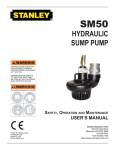
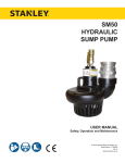
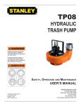
SM50
HYDRAULIC
SUMP PUMP
WARNING
SAFETY, OPERATION AND MAINTENANCE
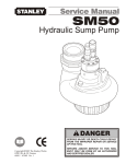
SERVICE MANUAL
© 2005 The Stanley Works
SVCE/MAINT USA
Printed in U.S.A.
60195 9/2005 ver 2
Stanley Hydraulic Tools
3810 SE Naef Road
Milwaukie OR 97267-5698
503-659-5660
FAX 503-652-1780
www.stanley-hydraulic-tools.com
TABLE OF CONTENTS
CERTIFICATE OF CONFORMITY ................................................................................................4
SAFETY SYMBOLS ......................................................................................................................5
SAFETY PRECAUTIONS .............................................................................................................6
TOOL STICKERS & TAGS ............................................................................................................8
HYDRAULIC HOSE REQUIREMENTS ........................................................................................9
HTMA REQUIREMENTS ............................................................................................................10
OPERATION ...............................................................................................................................11
PREOPERATION PROCEDURES.............................................................................................. 11
CHECK POWER SOURCE ......................................................................................................... 11
CONNECT HOSES ..................................................................................................................... 11
PUMP OPERATION .................................................................................................................... 11
COLD WEATHER OPERATION .................................................................................................. 11
MAINTENANCE ..........................................................................................................................12
CLEANING THE PUMPING CHAMBER .....................................................................................12
EQUIPMENT PROTECTION & CARE ........................................................................................13
TROUBLESHOOTING ................................................................................................................14
SPECIFICATIONS.......................................................................................................................15
ACCESSORIES ..........................................................................................................................15
SERVICE.....................................................................................................................................16
PARTS ILLUSTRATION ..............................................................................................................19
PARTS LIST ................................................................................................................................20
WARRANTY ................................................................................................................................21
SERVICING THE STANLEY HYDRAULIC Sump Pump. This manual contains safety, operation, and routine
maintenance instructions. Stanley Hydraulic Tools recommends that servicing of hydraulic tools, other
than routine maintenance, be performed by an authorized and certified dealer. Please read the following
warning.
WARNING
SERIOUS INJURY OR DEATH COULD RESULT FROM THE IMPROPER REPAIR OR SERVICE OF THIS TOOL.
REPAIRS AND / OR SERVICE TO THIS TOOL MUST ONLY BE
DONE BY AN AUTHORIZED AND CERTIFIED DEALER.
For the nearest authorized and certified dealer, call Stanley Hydraulic Tools at the number listed on the
back of this manual and ask for a Customer Service Representative.
3
CERTIFICATE OF CONFORMITY
CERTIFICATE OF CONFORMITY
ÜBEREINSTIMMUNGS-ZERTIFIKAT
CERTIFICAT DE CONFORMITE CEE
CERTIFICADO DE CONFORMIDAD
CERTIFICATO DI CONFORMITA
Hydraulic Tools
______________________________________________________________________
I, the undersigned:
Ich, der Unterzeichnende:
Je soussigné:
El abajo firmante:
lo sottoscritto:
Winterling, David
Surname and First names/Familiennname und Vornamen/Nom et prénom/Nombre y apellido/Cognome e nome
hereby certify that the construction plant or equipment specified hereunder:
bestätige hiermit, daß das im folgenden genannten Werk oder Gerät:
certifies par ceci que l’ usine ou l’ équipement de construction indiqué cidessous:
por el presente certifico que la fabrica o el equipo especificado a continuacion:
certifico che l’impianto o l’attrezzatura sotto specificata:
1.
Category:
Kategorie:
Catégorie:
Categoria:
Categoria:
2.
Make/Ausführung/Marque/Marca/Marca
3.
4.
Type/Typ/Type/Tipo/Tipo:
SM50100
Serial number of equipment:
Seriennummer des Geräts:
Numéro de série de l’équipement:
Numero de serie del equipo:
Matricola dell´attrezzatura:
5.
Submersible Pump
Stanley
All
Year of manufacture/Baujahr/année de fabrication/Año de fabricacion/Anno di fabbricazione
2002
Has been manufactured in conformity with - EEC Type examination as shown.
Wurde hergestellt in Übereinstimmung mit - EEC Typ-Prüfung nach.
Est fabriqué conformément - au(x) type(s) examiné(s) comme indiqué dans le tableau ci-après.
Ha sido fabricado de acuerdo con - tipo examen EEC como dice.
E’ stata costruita in conformitá con - le norme CEE come illustrato.
Examen CEE de type
Directive
Richtlinie
Directives particulières
Directriz
Direttiva
No.
Nr
Numéro
No
n.
Date
Datum
Date
Fecha
Data
Approved body
Prüfung durch
Organisme agréé
Aprobado
Collaudato
Date of expiry
Ablaufdatum
Date d´expiration
Fecha de caducidad
Data di scadenza
EN
Machinery Directive
809
98/37/EC
1995
1998
Self
Self
NA
NA
6.
Special Provisions:
None
Spezielle Bestimmungen:
Dispositions particulières:
Provisiones especiales:
Disposizioni speciali:
Done at/Ort/Fait à/Dado en/Fatto a Stanley Hydraulic Tools, Milwaukie, Oregon USA
Date/Datum/le/Fecha/Data
2002
Signature/Unterschrift/Signature/Firma/Firma____________________________________________________________________________
Position/Position/Fonction/Puesto/Posizione
Engineering Manager
4
SAFETY SYMBOLS
Safety symbols and signal words, as shown below, are used to emphasize all operator, maintenance and repair
actions which, if not strictly followed, could result in a life-threatening situation, bodily injury or damage to equipment.
This is the safety alert symbol. It is used to alert you to potential personal
injury hazards. Obey all safety messages that follow this symbol to avoid
possible injury or death.
DANGER
This safety alert and signal word indicate an imminently hazardous situation which, if not avoided, will result in death or serious injury.
WARNING
This safety alert and signal word indicate a potentially hazardous situation
which, if not avoided, could result in death or serious injury.
CAUTION
This safety alert and signal word indicate a potentially hazardous situation
which, if not avoided, may result in minor or moderate injury.
This signal word indicates a potentially hazardous situation which, if not
avoided, may result in property damage.
NOTICE
This signal word indicates a situation which, if not avoided, will result in
damage to the equipment.
IMPORTANT
This signal word indicates a situation which, if not avoided, may result in
damage to the equipment.
Always observe safety symbols. They are included for your safety and for the protection of the tool.
LOCAL SAFETY REGULATIONS
Enter any local safety regulations here. Keep these instructions in an area accessible to the operator and maintenance personnel.
5
SAFETY PRECAUTIONS
Tool operators and maintenance personnel must always comply with the safety
precautions given in this manual and on the stickers and tags attached to the tool
and hose.
These safety precautions are given for your safety. Review them carefully before
operating the tool and before performing general maintenance or repairs.
Supervising personnel should develop additional precautions relating to the specific
work area and local safety regulations. If so, place the added precautions in the
space provided in this manual.
The models SM50 Hydraulic Pump will provide safe and dependable service if operated in accordance with the instructions given in this manual. Read and understand
this manual and any stickers and tags attached to the pump and hoses before
operation. Failure to do so could result in personal injury or equipment damage.
• Operator must start in a work area without bystanders. The operator must be familiar with all prohibited work areas
such as excessive slopes and dangerous terrain conditions.
• Establish a training program for all operators to ensure safe operations.
• Do not operate the tool unless thoroughly trained or under the supervision of an instructor.
• Always wear safety equipment such as goggles, head protection, and safety shoes at all times when operating
the tool.
• Do not inspect or clean the tool while the hydraulic power source is connected. Accidental engagement of the
tool can cause serious injury.
• Do not operate this tool without first reading the Operating Instructions.
• Do not install or remove this tool while the hydraulic power source is connected. Accidental engagement of
the tool can cause serious injury.
• Never operate the tool near energized transmission lines. know the location of buried or covered services before starting work.
• Do not wear loose fitting clothing when operating the tool. Loose fitting clothing can get entangled with the
tool and cause serious injury.
• Supply hoses must have a minimum working pressure rating of 2500 psi/175 bar.
• Be sure all hose connections are tight.
• The hydraulic circuit control valve must be in the “OFF” position when coupling or uncoupling the tool. Wipe all couplers
clean before connecting. Failure to do so may result in damage to the quick couplers and cause
overheating. Use only lint-free cloths.
• Do not operate the tool at oil temperatures above 140° F/60° C. Operation at higher oil temperatures can
cause operator discomfort and may cause damage to the tool.
• Do not operate a damaged, improperly adjusted, or incompletely assembled tool.
6
SAFETY PRECAUTIONS
• To avoid personal injury or equipment damage, all tool repair, maintenance and service must only be
performed by authorized and properly trained personnel.
• Do not exceed the rated limits of the tool or use the tool for applications beyond its design capacity.
• Always keep critical tool markings, such as labels and warning stickers legible.
• Always replace parts with replacement parts recommended by Stanley Hydraulic Tools.
• Check fastener tightness often and before each use daily.
7
TOOL STICKERS & TAGS
CAUTION
52728
SM50 Combined Decal
D A N G E R
D A N G E R
1. FAILURE TO USE HYDRAULIC HOSE LABELED
AND CERTIFIED AS NON-CONDUCTIVE WHEN
USING HYDRAULIC TOOLS ON OR NEAR
ELECTRICAL LINES MAY RESULT IN DEATH
OR SERIOUS INJURY.
BEFORE USING HOSE LABELED AND CERTIFIED AS NON-CONDUCTIVE ON OR NEAR
ELECTRIC LINES BE SURE THE HOSE IS
MAINTAINED AS NON-CONDUCTIVE. THE
HOSE SHOULD BE REGULARLY TESTED FOR
ELECTRIC CURRENT LEAKAGE IN ACCORDANCE WITH YOUR SAFETY DEPARTMENT
INSTRUCTIONS.
2.
A HYDRAULIC LEAK OR BURST MAY CAUSE
OIL INJECTION
INTO THE
BODY OR CAUSE OTHER SEVERE PERSONAL
INJURY.
A DO NOT EXCEED SPECIFIED FLOW AND
PRESSURE FOR
The safety tag (p/n
15875) at right is attached
to the tool when shipped
from the factory. Read
and understand the safety
instructions listed on this
tag before removal. We
suggest you retain this tag
and attach it to the tool
when not in use.
3. MAKE SURE HYDRAULIC HOSES ARE PROPERLY CONNECTED TO THE TOOL BEFORE
PRESSURING SYSTEM. SYSTEM PRESSURE
HOSE MUST ALWAYS BE CONNECTED TO TOOL
“IN” PORT. SYSTEM RETURN HOSE MUST
ALWAYS BE CONNECTED TO TOOL “OUT” PORT.
REVERSING CONNECTIONS MAY CAUSE REVERSE TOOL OPERATION WHICH CAN RESULT
IN SEVERE PERSONAL INJURY.
4. DO NOT CONNECT OPEN-CENTER TOOLS TO
CLOSED-CENTER HYDRAULIC SYSTEMS. THIS
MAY RESULT IN LOSS OF OTHER HYDRAULIC
FUNCTIONS POWERED BY THE SAME SYSTEM
AND/OR SEVERE PERSONAL INJURY.
5. BYSTANDERS MAY BE INJURED IN YOUR WORK
AREA. KEEP BYSTANDERS CLEAR OF YOUR
WORK AREA.
IMPORTANT
IMPORTANT
READ OPERATION MANUAL AND
SAFETY INSTRUCTIONS FOR THIS
TOOL BEFORE USING IT.
READ OPERATION MANUAL AND
SAFETY INSTRUCTIONS FOR THIS
TOOL BEFORE USING IT.
USE ONLY PARTS AND REPAIR
PROCEDURES APPROVED BY
STANLEY AND DESCRIBED IN THE
OPERATION MANUAL.
USE ONLY PARTS AND REPAIR
PROCEDURES APPROVED BY
STANLEY AND DESCRIBED IN THE
OPERATION MANUAL.
TAG TO BE REMOVED ONLY BY
TOOL OPERATOR.
TAG TO BE REMOVED ONLY BY
TOOL OPERATOR.
SAFETY TAG P/N 15875
8
D DO NOT LIFT OR CARRY TOOL BY THE
HOSES. DO NOT ABUSE HOSE. DO NOT
USE KINKED, TORN OR DAMAGED HOSE.
(shown smaller then actual size)
HYDRAULIC HOSE REQUIREMENTS
HOSE TYPES
Hydraulic hose types authorized for use with Stanley Hydraulic Tools are as follows:
Certified non-conductive
Wire-braided (conductive)
Fabric-braided (not certified or labeled non-conductive)
Hose listed above is the only hose authorized for use near electrical conductors.
Hoses and listed above are conductive and must never be used near electrical conductors.
HOSE SAFETY TAGS
To help ensure your safety, the following DANGER tags are attached to all hose purchased from Stanley Hydraulic Tools. DO NOT REMOVE THESE TAGS.
If the information on a tag is illegible because of wear or damage, replace the tag immediately. A new tag may be
obtained from your Stanley Distributor.
D A N G E R
D A N G E R
1 FAILURE TO USE HYDRAULIC HOSE LABELED AND CERTIFIED AS NON-CONDUCTIVE
WHEN USING HYDRAULIC TOOLS ON OR NEAR ELECTRIC LINES MAYRESULT IN DEATH
OR SERIOUS INJURY.
FOR PROPER AND SAFE OPERATION MAKE SURE THAT YOU HAVE BEEN PROPERLY
TRAINED IN CORRECT PROCEDURES REQUIRED FOR WORK ON OR AROUND
ELECTRIC LINES.
3. DO NOT EXCEED HOSE WORKING PRESSURE OR ABUSE HOSE. IMPROPER USE OR
HANDLING OF HOSE COULD RESULT IN BURST OR OTHER HOSE FAILURE. KEEP
HOSE AS FAR AWAY AS POSSIBLE FROM BODY AND DO NOT PERMIT DIRECT CONTACT
DURING USE. CONTACT AT THE BURST CAN CAUSE BODILY INJECTION AND SEVERE
PERSONAL INJURY.
4. HANDLE AND ROUTE HOSE CAREFULLY TO AVOID KINKING, ABRASION, CUTTING, OR
CONTACT WITH HIGH TEMPERATURE SURFACES. DO NOT USE IF KINKED. DO NOT USE
HOSE TO PULL OR LIFT TOOLS, POWER UNITS, ETC.
2. BEFORE USING HYDRAULIC HOSE LABELED AND CERTIFIED AS NON-CONDUCTIVE ON
OR NEAR ELECTRIC LINES. WIPE THE ENTIRE LENGTH OF THE HOSE AND FITTING
WITH A CLEAN DRY ABSORBENT CLOTH TO REMOVE DIRT AND MOSISTURE AND TEST
HOSE FOR MAXIMUM ALLOWABLE CURRENT LEAKAGE IN ACCORDANCE WITH SAFETY
DEPARTMENT INSTRUCTIONS.
5. CHECK ENTIRE HOSE FOR CUTS CRACKS LEAKS ABRASIONS, BULGES, OR DAMAGE TO
COUPLINGS IF ANY OF THESE CONDITIONS EXIST, REPLACE THE HOSE IMMEDIATELY.
NEVER USE TAPE OR ANY DEVICE TO ATTEMPT TO MEND THE HOSE.
6. AFTER EACH USE STORE IN A CLEAN DRY AREA.
SIDE 1
3
DO NOT REMOVE THIS TAG
DO NOT REMOVE THIS TAG
THE TAG SHOWN BELOW IS ATTACHED TO “CERTIFIED NON-CONDUCTIVE” HOSE
SIDE 2
(shown smaller than actual size)
D A N G E R
D A N G E R
1 DO NOT USE THIS HYDRAULIC HOSE ON OR NEAR ELECTRIC LINES. THIS HOSE IS
NOT LABELED OR CERTIFIED AS NON-CONDUCTIVE. USING THIS HOSE ON OR NEAR
ELECTRICAL LINES MAY RESULT IN DEATH OR SERIOUS INJURY.
5. CHECK ENTIRE HOSE FOR CUTS CRACKS LEAKS ABRASIONS, BULGES, OR DAMAGE TO
COUPLINGS IF ANY OF THESE CONDITIONS EXIST, REPLACE THE HOSE IMMEDIATELY.
NEVER USE TAPE OR ANY DEVICE TO ATTEMPT TO MEND THE HOSE.
2. FOR PROPER AND SAFE OPERATION MAKE SURE THAT YOU HAVE BEEN PROPERLY
TRAINED IN CORRECT PROCEDURES REQUIRED FOR WORK ON OR AROUND
ELECTRIC LINES.
6. AFTER EACH USE STORE IN A CLEAN DRY AREA.
3. DO NOT EXCEED HOSE WORKING PRESSURE OR ABUSE HOSE. IMPROPER USE OR
HANDLING OF HOSE COULD RESULT IN BURST OR OTHER HOSE FAILURE. KEEP
HOSE AS FAR AWAY AS POSSIBLE FROM BODY AND DO NOT PERMIT DIRECT CONTACT
DURING USE. CONTACT AT THE BURST CAN CAUSE BODILY INJECTION AND SEVERE
PERSONAL INJURY.
4. HANDLE AND ROUTE HOSE CAREFULLY TO AVOID KINKING, CUTTING, OR CONTACT
WITH HIGH TEMPERATURE SURFACES. DO NOT USE IF KINKED. DO NOT USE HOSE TO
PULL OR LIFT TOOLS, POWER UNITS, ETC.
DO NOT REMOVE THIS TAG
DO NOT REMOVE THIS TAG
THE TAG SHOWN BELOW IS ATTACHED TO “CONDUCTIVE” HOSE.
SEE OTHER SIDE
SIDE 1
SIDE 2
(shown smaller than actual size)
HOSE PRESSURE RATING
The rated working pressure of the hydraulic hose must be equal to or higher than the relief valve setting on the
hydraulic system.
9
HTMA REQUIREMENTS
TOOL CATEGORY
HYDRAULIC SYSTEM
REQUIREMENTS
FLOW RATE
TYPE 1
TYPE II
7-9 gpm
(26-34 lpm)
2000 psi
(138 bar)
TYPE III
TOOL OPERATING PRESSURE
(at the power supply outlet)
4-6 gpm
(15-23 lpm)
2000 psi
(138 bar)
SYSTEM RELIEF VALVE SETTING
(at the power supply outlet)
2100-2250 psi 2100-2250 psi 2100-2250 psi 2200-2300 psi
(145-155 bar) (145-155 bar) (145-155 bar) (152-159 bar)
MAXIMUM BACK PRESSURE
(at tool end of the return hose)
250 psi
(17 bar)
Measured at a max. fluid viscosity of:
(at min. operating temperature)
400 ssu*
400 ssu*
400 ssu*
400 ssu*
(82 centistokes) (82 centistokes) (82 centistokes) (82 centistokes)
TEMPERATURE
Sufficient heat rejection capacity
to limit max. fluid temperature to:
(at max. expected ambient temperature)
140° F
(60° C)
140° F
(60° C)
140° F
(60° C)
140° F
(60° C)
Min. cooling capacity
at a temperature difference of
between ambient and fluid temps
3 hp
(2.24 kW)
40° F
(22° C)
5 hp
(3.73 kW)
40° F
(22° C)
7 hp
(4.47 kW)
40° F
(22° C)
6 hp
(5.22 kW)
40° F
(22° C)
250 psi
(17 bar)
11-13 gpm
(42-49 lpm)
2000 psi
(138 bar)
TYPE RR
250 psi
(17 bar)
9-10.5 gpm
(34-40 lpm)
2000 psi
(138 bar)
250 psi
(17 bar)
NOTE:
Do not operate the tool at oil temperatures above 140° F (60° C). Operation at higher temperatures can cause operator
discomfort at the tool.
FILTER
25 microns
Min. full-flow filtration
30 gpm
Sized for flow of at least:
(114 lpm)
(For cold temp. startup and max. dirt-holding capacity)
25 microns
30 gpm
(114 lpm)
HYDRAULIC FLUID
Petroleum based
(premium grade, anti-wear, non-conductive)
VISCOSITY
(at min. and max. operating temps)
100-400 ssu* 100-400 ssu*
(20-82 centistokes)
100-400 ssu*
25 microns
30 gpm
(114 lpm)
25 microns
30 gpm
(114 lpm)
100-400 ssu*
NOTE:
When choosing hydraulic fluid, the expected oil temperature extremes that will be experienced in service determine the
most suitable temperature viscosity characteristics. Hydraulic fluids with a viscosity index over 140 will meet the requirements over a wide range of operating temperatures.
*SSU = Saybolt Seconds Universal
NOTE:
These are general hydraulic system requirements. See tool Specification page for tool specific requirements.
10
OPERATION
PREOPERATION PROCEDURES
CHECK POWER SOURCE
1. Using a calibrated flow meter and pressure gauge, make
sure the hydraulic power source develops a flow of 7-12
gpm/26-45 Ipm at 1000-2000 psi/70-140 bar.
2. Make certain that the power source is equipped with a
relief valve set to open at 2100 psi/145 bar maximum.
2. Connect a hose fitted with a 3 inch/76.2 mm female camlock coupler to the pump outlet fitting. Make sure the fitting
is securely tightened. For best performance, keep the hose
as short as possible and lay it out to avoid sharp bends or
kinks.
3. Lower the pump into the liquid to be pumped. Locate the
outlet end of the discharge hose to disperse the liquid as
required. Remove any kinks from thehose to assure maximum water flow.
IMPORTANT
3. Make certain that the power source return pressure does
not exceed 250 psi/17 bar.
4. Make sure the trash pump inlet is clear of debris. Remove any obstruction before operating. Refer to PUMP
CLEANING PROCEDURES.
CONNECT HOSES
1. Wipe all hose couplers with a clean lint free cloth before
making connections.
2. Connect the hoses from the hydraulic power source to
the couplers on the trash pump or trash pump hoses. It is a
good practice to connect return hose first and disconnect it
last to minimize or avoid trapped pressure within the trash
pump motor.
Note:
If uncoupled hoses are left in the sun, pressure increase inside the hoses might make them difficult to
connect. Whenever possible, connectthe free ends of
the hoses together.
3. Observe the arrow on the couplers to ensure that the
flow is in the proper direction. The female coupler on the
trash pump is the inlet (pressure) coupler.
PUMP OPERATION
1. Observe all safety precautions.
Note:
The SM50 is not desgined for use with a suction pipe
inlet. The diameter of the suction screen at the bottom of the pump provides madimum pump efficiency.
Reducing the size of this inlet will greatly reduce pump
performance.
Never point the hose at bystanders.
4. Turn on the hydraulic power source. Watch for solids in
the liquid being pumped. If solids are excessive, the discharge flow might decrease. If this happens, stop the pump
and check for the cause of the problem.
Under some conditions, the liquid being pumped might be
slowed enough so It can no longer push particles in the
liquid. If this happens, particles can accumulate in the hose
and backup the pumping chamber, causing further restriction. The impeller then acts as a “grinding wheel which
causes accelerated pump wear. Reduced liquid flow can be
caused by the following:
• The pump sinks into solids at the bottom of the hole.
• The end of the outlet hose is too high, causing an excessive lift height for the column of liquid being pushed by the
trash pump. This slows the flow of liquid to a level where it
can no longer carry solids out the end of the hose.
• The flow and pressure of hydraulic fluid to the pump is
too low, which reduces impeller speed. A 20% decrease in
hydraulic fluid flow can reduce pump performance by 50%.
When operating at reduced hydraulic flow and pressure, the
end of the outlet hose should not be more than 30 ft/9 m
above the liquid.
5. When pumping is complete, set the hydraulic control
valve to the “OFF” position. Lift the pump from the work
area.
COLD WEATHER OPERATION
If the trash pump is to be used during cold weather, preheat
the hydraulic fluid at low power source speed. When using
the normally recommended fluids, fluid should be at or
above 50°FI1 DoC (400 ssu/82 centistokes) before use.
Damage to the hydraulic system or pump motor seals can
result from use with fluid that is too viscous or thick.
11
MAINTENANCE
CLEANING THE PUMPING
CHAMBER
Debris such as weeds, sand and other solids may become
trapped in the water hose and pumping chamber. This can
reduce pump performance. It is important that the pumping
chamber be kept clean at all times. The chamber can be
cleaned as follows:
1. Remove motor and impeller by removing the two M12 x
1.75 Hex Head capscrews.
2. Remove all debris from the pump screen.
3. Thoroughly clean the volute and impeller. Do not remove
the impeller unless necessary for repair or replacement or
to remove trapped debris.
4. Assemble the motor and impeller to the volute. Clean
the capscrews and lubricate the threads with underwater
grease before installation.
5. Remove all debris from the hose. Otherwise, solids will
backfill the pump.
12
EQUIPMENT PROTECTION & CARE
NOTICE
In addition to the Safety
Precautions in this manual,
observe the following for
equipment protection and
care.
• Make sure all couplers are wiped clean before connection.
• The hydraulic circuit control valve must be in the “OFF” position when coupling or uncoupling
hydraulic tools. Failure to do so may result in damage to the quick couples and cause overheating
of the hydraulic system.
• Always store the tool in a clean dry space, safe from damage or pilferage.
• Make sure the circuit PRESSURE hose (with male quick disconnect) is connected to the “IN” port.
The circuit RETURN hose (with female quick disconnect) is connected to the opposite port. Do not
reverse circuit flow. This can cause damage to internal seals.
• Always replace hoses, couplings and other parts with replacement parts recommended by Stanley
Hydraulic Tools. Supply hoses must have a minimum working pressure rating of 2500 psi/172 bar.
• Do not exceed the rated flow (see Specifications) in this manual for correct flow rate and
model number. Rapid failure of the internal seals may result.
• Always keep critical tool markings, such as warning stickers and tags legible.
• Do not use the tool for applications it was not designed for.
• Tool repair should be performed by experienced personnel only.
• Make certain that the recommended relief valves are installed in the pressure side of the system.
• Do not use the tool for applications for which it was not intended.
13
TROUBLESHOOTING
If symptoms of poor performance develop, the following chart can be used as a guide to correct the problem.
When diagnosing faults in operation, always make sure the hydraulic power source is supplying the correct hydraulic flow
and pressure as listed in the table. Use a flowmeter know to be accurate. Check the flow with the hydraulic fluid temperature at least 80o F/27o C.
PROBLEM
CAUSE
No hydraulic fluid flow or pressure.
Pump will not start.
Turn on power unit and check that 7-12
gpm/26-45 lpm at 1000-2000 psi/70-140
bar is available at the pump.
Defective couplers.
Check the couplers. Replace if necessary.
Impeller jammed with debris.
Clean the pumping chamber as described
in the Maintenance section in this manual.
Impeller rubbing against wear plates.
Check and adjust the impeller clearance
as described in the Service Instructions
section in this manual.
Defective hydraulic motor.
Repair or replace motor.
Hydraulic flow reversed.
Check that the hoses are correctly connected to the pump motor ports. The
female coupler should be connected to the
“IN” port. The return fluid must never flow
through a reversing valve.
Improper hydraulic fluid flow.
Check that 7-12 gpm/26-45 lpm at 10002000 psi/70-140 bar is available at the
trash pump. A 20% decrease in flow can
result in a 50% decrease in pump performance.
Pump submersed in sediment.
Lift the pump from the bottom of the hole
or chamber. Use a flat support under the
pump if necessary.
Trash pump inlet restricted.
Remove suction screen and thoroughly
clean. Reassemble.
Discharge hose kinked or restricted.
Straighten the hose. If the hose must bend
at the top of the hole, use a piece of split
rigid conduit with large diameter of the
expanded hose. This keeps the hose from
kinking.
Discharge hose too small.
Use a 3-inch diameter fire hose.
Water lift too high.
Lower the outlet end of the discharge
hose. Increase hydraulic flow (12 gpm/45
lpm max).
Impeller worn or damaged.
Check impeller for damage and excessive
wear. Replace if necessary.
Pump not matched to application
Obtain higher capacity pump.
Hose used on suction side of pump.
Remove. Use no plumbing on suction side
of pump.
Too many solids in the water. Water speed
out of the hose may be too slow, thereofre
hose and pump load up with solids.
Reduce solids content. Increase pump
speed.
Poor pump performance.
Poor pump performance with excessive
wear.
SOLUTION
14
SPECIFICATIONS
Capacity ................................................................................................................................................... 500 gpm/1890 lpm
Weight ............................................................................................................................................................... 21 lbs/9.5 kg
Length .......................................................................................................................................................... 10.5 in./26.7 cm
Width ............................................................................................................................................................... 10 in./25.4 cm
Pressure ....................................................................................................................................... 1000-2000 psi/70-140 bar
Flow Range ........................................................................................................................................... 7-12 gpm/26-45 lpm
Maximum Flow ............................................................................................................................................... 12 gpm/45 lpm
Porting ............................................................................................................................................................. -8SAE O-Ring
Connect Size and Type .................................................................................3/8 in. Flush Face Quick Disconnect Couplers
Discharge Diameter ............................................................................................................................................. 3 in./7.6 cm
Sound Pressure ............................................................................................................................................ <85 dBA @ 1 m
ACCESSORIES
Description
Part No.
Adapter, 3 in. NPT/3 in. Camlock Male ........................................................................................................................52720
Lay-Flat Discharge Hose, 3 in. x 25 ft with Camlock Fittings .......................................................................................56761
Adapter, 3 in. Femaile Camlock x Male Fire Hose (nh) Thread....................................................................................15248
15
SERVICE
DRIVE SHAFT
TOOL DISASSEMBLY /
REASSEMBLY
1. Remove idler gear (29), idler shaft (30), drive gear (28),
and needle roller (19) from front bearing housing.
Note: For orientation of parts in the following procedures,
refer to the parts drawing later in this manual.
2. Remove the v-ring (6) from the seal race (14) before pulling the seal race off the drive shaft.
PRIOR TO DISASSEMBLY
3. Remove retaining ring (9).
1. Clean the exterior of the tool and place on a clean work
surface.
4. Using a pick, remove the seal carrier (10), cup seal (12),
o-ring (11), seal retainer (13), and o-ring (15) from the bearing cavity.
2. Obtain the seal kit listed on the PARTS LIST so all seals
exposed during disassembly can be replaced.
5. Press the drive shaft (17) and bearings (16) from the
front bearing housing.
PRIOR TO REASSEMBLY
6. Spin the ball bearings on the drive shaft. The bearing should turn smoothly. To replace the bearing, support
the outer race and press down on the drive shaft from the
threaded end. Do not reuse the ball bearing once it has
been removed from the drive shaft.
1. Clean all parts with a degreasing solution
2. Blow dry all parts or use lint-free cloths.
3. Ensure that all seals exposed during disassembly are
replaced with new parts.
DRIVE SHAFT SEAL
4. Apply clean grease or o-ring lubricant to all parts during
assembly.
1. Remove the retaining ring (20), quad ring (21), seal
gland (22) and o-ring (23) from the drive shaft bore using a
pick.
TOOL DISASSEMBLY
CLEANING AND INSPECTION
VOLUTE
CLEANING
1. Remove the volute (1) by first removing the hex head
cap screws (25) and pulling the motor and impeller off the
volute.
Clean all parts with a degreasing solution. Blow dry with
compressed air or use lint-free cloths.
Gear Chamber (Motor Cap)
IMPELLER
The chamber bores and bottoms around the shaft bushings
should be polished and not rough or grooved. If the bushing bores are yellow-bronze, replace them and investigate
the cause of wear.
1. Remove hex socket head capscrew (3) and washer (4)
before lifting impeller (5) off motor assembly.
2. Remove key (18) and shim stack (7 & 8) from impeller.
MOTOR CAP
The flat surfaces around the chamber and bolt holes should
be flat and free of nicks or burrs that could cause misalignment or leaks.
1. Remove the hex socket head capscrews (33) that secure
the motor cap (31) to the front bearing housing (24) and
remove the motor cap. Do not in any way excessively force
the motor cap off the front bearing housing.
BUSHINGS
The inside of the bushings should be gray with some
bronze showing through. If significant yellow-bronze
shows, replace the bushings. Inspect the motor shaft and
idler shaft for corresponding wear and replace as required.
2. Remove the o-ring (26) from the motor cap.
16
SERVICE
GEARS
3. Lubricate and install o-ring (15) and seal race (14) onto
driveshaft.
The drive and idler gears should have straight tips without
nicks, square tooth ends, and a smooth even polish on the
teeth and end faces. Replace the gear if cracks are present.
4. Lubricate and install seal retainer (13) and o-ring (11)
into bearing bore.
The surface near the gears should show two interconnecting polished circles without a step.
5. Heavily lubricate with underwater grease and install cup
seal (12) and seal carrier (10) into bearing bore and secure
with retaining ring (9). Installation of seal carrier and cup
seal before seal race has been installed will result in damage to cup seal.
SHAFTS
6. Lubricate with underwater grease and install v-ring (6)
onto seal race.
FRONT BEARING HOUSING
The shaft diameter at the bearing and seal locations must
be smooth. Grooves, roughness or a reduced diameter
indicate fluid contamination or damaged bushings. Grit
particles may have been imbedded in the bushings, grinding into the hardened shaft. If abnormal shaft wear as
noted above occurs (more than normal polishing), replace
both the shaft and associated bushings.
7. Install idler shaft (30) and idler gear (29).
Also check the hydraulic system for excess contamination
in the fluid and for filter condition. Operating conditions
may require changing from a 25-micron filter to an oversized 10-micron filter.
1. Lubricate and install o-ring (26) into motor cap (31).
TOOL REASSEMBLY
8. Use grease to hold needle roller (19) in place before
installing drive gear (28).
MOTOR CAP
2. Lubricate hex socket head capscrews (33) with an
antiseize compound and install motor cap to front bearing
housing. Tighten capscrews to 8-10 ft.lb. Note the orientation of the motor cap as the bolt holes will only line up one
way.
DRIVE SHAFT SEAL
CAUTION
1. Heavily lubricate and install a new o-ring (23) and quad
ring (21) into seal gland (22). Ensure the quad ring is not
twisted during assembly.
2. Install seal gland and attached parts into front bearing
housing and secure with retaining ring (20).
Do not force parts together.
IMPELLER
1. Install shim stack (7&8) onto drive shaft.
DRIVE SHAFT
1 Install bearings (16) onto lubricated drive shaft (17) by
supporting the inner races of the bearings and pressing
drive shaft through bearings until the bearings rest against
the shoulder. Installation by the outer race will cause bearing damage.
2. Pack grease into needle roller groove on drive shaft
and insert drive shaft into the seal gland. Using a bearing
pusher or a sleeve / socket with a diameter slightly smaller
than the bearing bore, press the bearing assembly into
place using the outer race. Installation by the inner race
will result in bearing damage.
2. Install key (18) and impeller (5) to drive shaft and, using loctite, secure with washer (4) and hex socket head
capscrew (3). Tighten capscrew to 15 ft.lb.
3. Using a depth mic, measure the distance from the
bottom of the motor flange to the bottom of the stepped
diameter as shown below. Adjust shim stack accordingly to
achieve a 2.285 / 2.270 offset.
17
SERVICE
VOLUTE
1. Assemble motor and impeller to volute (1) and secure
with hex head cap screws (25).
2. Use an allen wrench to ensure that the impeller with freewheel after assembly.
18
PARTS ILLUSTRATION
35
36
19
17
34
18
16
33
15
65132 MOTOR ASSEMBLY
USED ON SUMP PUMPS
WITH SERIAL NUMBERS
600 AND ABOVE, THIS MOTOR
CAN ONLY BE PURCHASED
AS AN ASSEMBLY. INDIVIDUAL
PARTS ARE NOT AVAILABLE.
14
13
31
12
11
10
30
9
6
29
28
8
27
7
5
26
2
25
4
3
24
1
23
22
21
20
19
PARTS LIST
Item
No.
Part No.
Qty
Description
1
52669
1
Volute
2
52720
1
Camlock Coupling 3 in.
*NOTE: Items 9 through 24 and 26 through
31 and Item 33 Are Used On Sump Pumps
With Serial Numbers 599 And Below.
3
13815
1
HSHCS 5/16 - 18 x 3/4
4
56763
1
Washer
5
52671
1
Impeller
6
52716
1
V-Ring
7
31032
*
Shim .020
8
31033
*
Shim .010
9
00166
1
Retaining Ring
10
52719
1
Seal Carrier
11
01262
1
O-ring 1-3/4 x 1-7/8 x 1/16 -031
12
58651
1
Cup Seal
13
56658
1
Seal Retainer
14
56697
1
Seal Race
15
01211
1
O-ring 5/8 x 3/4 x 1/16 -016
16
00148
2
Bearing
17
52696
1
Drive Shaft
18
00635
1
Key
19
06881
1
Needle Roller
20
00170
1
Retaining Ring
21
00669
1
Quad Ring 1/2 x 5/8 x 1/16 - 014
22
19884
1
Seal Gland
23
00171
1
O-Ring 11/16 x 13/16 x 1/16 - 017
24
52693
1
Front Bearing Housing
25
52718
2
HHCS M12-1.75 x 30mm
All Pumps With A Serial Number of 600 And
Above, Come Shipped With P/N-65132 Motor Assembly Installed. A Separate Seal Kit
66398 Is Available For This Motor.
Pumps With S/N-599 And Below May Purchase Individual Parts As Shown Above Or
Purchase A Complete 65132 Motor Assy
26
00178
1
O-ring 2-1/8 x 2-1/4 x 1/16 - 034
27
06316
2
Bushing
28
06853
1
Drive Gear
29
06855
1
Idler Gear
30
06854
1
Idler Shaft
31
06857
1
Gear Housing
32
52728
1
Name Tag and Safety Sticker
33
00612
8
HSHCS 1/4-20 x 2-1/4
34
00936
2
Adapter
35
58856
1
Female Flush Face Coupler Body 3/8 NPT
36
58857
1
Male Flush Face Coupler Nose 3/8 NPT
58718
1
Coupler Set
52758
1
REPAIR KIT
52759
1
SEALKIT
20
WARRANTY
Stanley Hydraulic Tools (hereinafter called “Stanley”), subject to the exceptions contained below, warrants new hydraulic tools for a period of one year from the date of sale to
the first retail purchaser, or for a period of 2 years from the shipping date from Stanley, whichever period expires first, to be free of defects in material and/or workmanship at
the time of delivery, and will, at its option, repair or replace any tool or part of a tool, or new part, which is found upon examination by a Stanley authorized service outlet or by
Stanley’s factory in Milwaukie, Oregon to be DEFECTIVE IN MATERIAL AND/OR WORKMANSHIP.
EXCEPTIONS FROM WARRANTY
NEW PARTS: New parts which are obtained individually are warranted, subject to the exceptions herein, to be free of defects in material and/or workmanship at the time
of delivery and for a period of 6 months after the date of first usage. Seals and diaphragms are warranted to be free of defects in material and/or workmanship at the time
of delivery and for a period of 6 months after the date of first usage or 2 years after the date of delivery, whichever period expires first. Warranty for new parts is limited to
replacement of defective parts only. Labor is not covered.
FREIGHT COSTS: Freight costs to return parts to Stanley, if requested by Stanley for the purpose of evaluating a warranty claim for warranty credit, are covered under this
policy if the claimed part or parts are approved for warranty credit. Freight costs for any part or parts which are not approved for warranty credit will be the responsibility of the
individual.
SEALS & DIAPHRAGMS: Seals and diaphragms installed in new tools are warranted to be free of defects in material and/or workmanship for a period of 6 months after the
date of first usage, or for a period of 2 years from the shipping date from Stanley, whichever period expires first.
CUTTING ACCESSORIES: Cutting accessories such as breaker tool bits are warranted to be free of defects in material and or workmanship at the time of delivery only.
ITEMS PRODUCED BY OTHER MANUFACTURERS: Components which are not manufactured by Stanley and are warranted by their respective manufacturers.
a. Costs incurred to remove a Stanley manufactured component in order to service an item manufactured by other manufacturers.
ALTERATIONS & MODIFICATIONS: Alterations or modifications to any tool or part. All obligations under this warranty shall be terminated if the new tool or part is altered or
modified in any way.
NORMAL WEAR: any failure or performance deficiency attributable to normal wear and tear such as tool bushings, retaining pins, wear plates, bumpers, retaining rings and
plugs, rubber bushings, recoil springs, etc.
INCIDENTAL/CONSEQUENTIAL DAMAGES: To the fullest extent permitted by applicable law, in no event will STANLEY be liable for any incidental, consequential or special
damages and/or expenses.
FREIGHT DAMAGE: Damage caused by improper storage or freight handling.
LOSS TIME: Loss of operating time to the user while the tool(s) is out of service.
IMPROPER OPERATION: Any failure or performance deficiency attributable to a failure to follow the guidelines and/or procedures as outlined in the tool’s operation and
maintenance manual.
MAINTENANCE: Any failure or performance deficiency attributable to not maintaining the tool(s) in good operating condition as outlined in the Operation and Maintenance
Manual.
HYDRAULIC PRESSURE & FLOW, HEAT, TYPE OF FLUID: Any failure or performance deficiency attributable to excess hydraulic pressure, excess hydraulic back-pressure, excess hydraulic flow, excessive heat, or incorrect hydraulic fluid.
REPAIRS OR ALTERATIONS: Any failure or performance deficiency attributable to repairs by anyone which in Stanley’s sole judgement caused or contributed to the failure
or deficiency.
MIS-APPLICATION: Any failure or performance deficiency attributable to mis-application. “Mis-application” is defined as usage of products for which they were not originally
intended or usage of products in such a matter which exposes them to abuse or accident, without first obtaining the written consent of Stanley. PERMISSION TO APPLY ANY
PRODUCT FOR WHICH IT WAS NOT ORIGINALLY INTENDED CAN ONLY BE OBTAINED FROM STANLEY ENGINEERING.
WARRANTY REGISTRATION: STANLEY ASSUMES NO LIABILITY FOR WARRANTY CLAIMS SUBMITTED FOR WHICH NO TOOL REGISTRATION IS ON RECORD. In
the event a warranty claim is submitted and no tool registration is on record, no warranty credit will be issued without first receiving documentation which proves the sale of
the tool or the tools’ first date of usage. The term “DOCUMENTATION” as used in this paragraph is defined as a bill of sale, or letter of intent from the first retail customer. A
WARRANTY REGISTRATION FORM THAT IS NOT ALSO ON RECORD WITH STANLEY WILL NOT BE ACCEPTED AS “DOCUMENTATION”.
NO ADDITIONAL WARRANTIES OR REPRESENTATIONS
This limited warranty and the obligation of Stanley thereunder is in lieu of all other warranties, expressed or implied including merchantability or fitness for a particular purpose
except for that provided herein. There is no other warranty. This warranty gives the purchaser specific legal rights and other rights may be available which might
vary depending upon applicable law.
21
Stanley Hydraulic Tools
3810 SE Naef Road
Milwaukie, Oregon
503-659-5660 / Fax 503-652-1780
www.stanley-hydraulic-tools.com