1
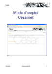
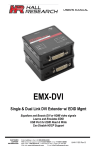
Noise Sentry
User’s Manual
September 25 2010
Bruno Paillard
1
INTRODUCTION ______________________________________________ 3
2
APPLICATIONS_______________________________________________ 3
3
WARNINGS __________________________________________________ 3
4
GETTING STARTED ___________________________________________ 4
4.1.1
4.1.2
4.1.3
Software Installation _________________________________________________________ 4
Hardware Installation_________________________________________________________ 4
Initial Test and Configuration __________________________________________________ 4
5
INSTRUMENT FUNCTIONS AND DESCRIPTION ____________________ 4
6
PRINCIPLES OF OPERATION ___________________________________ 5
6.1
Power-On / Power-Off Behaviour _________________________________________________ 6
6.2
Sampling Modes________________________________________________________________ 6
6.3
Recording _____________________________________________________________________ 6
6.4
Ongoing vs. Recorded Statistics ___________________________________________________ 7
6.5
LED indicator and Alarms _______________________________________________________ 7
6.6
Button Functions _______________________________________________________________ 8
6.7
Battery Life ___________________________________________________________________ 8
7
NOISE_SENTRY _MANAGER APPLICATION_______________________ 9
7.1
Starting the Application ________________________________________________________ 11
7.2
Main Functions _______________________________________________________________ 12
7.3
Setup Tab ____________________________________________________________________ 12
7.3.1
Time and Date Field ________________________________________________________ 12
7.3.2
Recording Setup Field _______________________________________________________ 12
7.3.3
Ongoing Measurements and Statistics Field ______________________________________ 13
7.3.4
Alarms ___________________________________________________________________ 13
7.3.5
Tracking Field _____________________________________________________________ 13
7.3.6
Button Function ____________________________________________________________ 13
7.3.7
Battery Condition Field ______________________________________________________ 13
7.3.8
Web Remote Button ________________________________________________________ 14
7.4
Log Tab _____________________________________________________________________ 14
7.5
Frequency Tab ________________________________________________________________ 14
Noise Sentry User’s Manual
1
7.6
Remote Control from Web Browser ______________________________________________ 15
7.6.1
Remote Access Setup on a Local Network _______________________________________ 16
7.6.2
Remote Access Setup On The Internet Behind A Remote Router______________________ 16
8
IMPROVING COMMUNICATION SPEED __________________________ 17
9
MAINTENANCE ______________________________________________ 17
9.1
Battery Change _______________________________________________________________ 17
9.1.1
Reset Procedure ____________________________________________________________ 18
9.1.2
Battery Type ______________________________________________________________ 18
9.2
Cleaning _____________________________________________________________________ 18
9.3
Software and Firmware Upgrades ________________________________________________ 19
10
TROUBLESHOOTING _______________________________________ 19
10.1
Cable Driver Installation _______________________________________________________ 19
10.2
Connection Problems __________________________________________________________ 19
11
SPECIFICATIONS __________________________________________ 19
12
FREQUENCY RESPONSE (TYPICAL) __________________________ 20
13
LINEARITY ________________________________________________ 21
14
SPECIFICATIONS OF NOISE_SENTRY _MANAGER SOFTWARE ___ 21
Noise Sentry User’s Manual
2
1
Introduction
The Noise Sentry is a high-performance integrating Sound Level Meter and data logger. It includes a
sensitive microphone, an accurate date/time clock and a non-volatile 52000-point recording memory. It
can integrate and record sound levels for up to 10 days. Its very small size allows it to be worn, or
embedded within monitored equipment.
The sound level meter includes the following features:
•
•
•
•
•
•
•
•
•
•
•
All-Digital design
Individual digital frequency correction and calibration
Frequency spectrum
dB-A and dB-C weighting functions.
Measures and records max, average and min levels over adjustable intervals.
An alarm function activates on the instantaneous peak level or the integrated dose.
Fast and Slow sampling modes.
Can monitor and record acoustic levels for up to 10 days on a small coin battery.
Non-volatile memory. In case of battery failure, all recorded data is preserved.
Noise_Sentry_Manager application to setup operating and recording parameters, download,
visualize and export the recorded data. The application can also be used to monitor acoustic
levels in real time.
Remote control from web browser.
2
Applications
•
•
•
•
Measurement and data-logging of acoustic dose.
Monitoring of safe working conditions.
Activity detection and recording.
Long-term measurement and recording of acoustic levels for environmental impact studies.
3
Warnings
Do not operate the Noise Sentry to temperatures exceeding the following limits:
•
-20 degC to 70 degC (-4 degF to 158 degF)
Do not submerge the Noise Sentry in liquids.
Only use the MLI cable provided with the Noise Sentry.
Only use the Noise Sentry as specified in this manual.
Noise Sentry User’s Manual
3
4
Getting Started
4.1.1 Software Installation
1 Run Noise_Sentry_Installer.exe. This installs the Noise_Sentry_Manager application, as well as its
MLI cable driver and documentation.
Note:
Perform the software installation above BEFORE connecting the MLI cable into the PC.
4.1.2 Hardware Installation
1 Connect the MLI cable into an available USB port of the PC
2 Verify that the PC properly detects the cable and loads the driver. In case of doubt see the
Troubleshooting section.
4.1.3 Initial Test and Configuration
1 If this is not already the case, insert a fresh CR2032 battery in the battery compartment. Be careful
about battery polarity. See the Battery Change subsection in the Maintenance section for detailed
instructions.
2 Upon battery insertion the LED starts blinking rapidly for a few seconds, then at a rate of once
every two seconds. If this is not the case remove the battery, perform the reset procedure (see
below) and insert the battery again.
3 Connect the MLI cable into an available USB port of the PC.
4 Connect the other end of the MLI cable into the side of the Noise Sentry.
5 Go into Start\All Programs\Noise Sentry, and run Noise_Sentry_Manager.exe. The front-panel
described in figure 3 appears, and the application tries to connect to the unit. If it fails to find the unit
it indicates No Device Found and closes. If this is the case see the Troubleshooting section.
Otherwise the application switches-on the Noise Sentry and starts communicating with it.
6 If the Time and Date in the upper right corner of the application window are not properly adjusted
the application asks if you want the time to be synchronized with the PC time.
7 Upon stopping the application the Noise Sentry is switched off, except if it is recording.
5
Instrument Functions and Description
The instrument measures and optionally records:
•
•
•
•
•
Instantaneous acoustic level
Max acoustic level
Min acoustic level
Average acoustic level (Equivalent Level or acoustic dose)
Time
The unit connects to a PC via its MLI adapter cable. The Noise_Sentry_Manager application is used to
set its operating parameters and download recordings.
Note:
Only use the MLI cable provided with the Noise Sentry.
Noise Sentry User’s Manual
4
Figure 1:
1.
2.
3.
4.
MLI cable connector
LED indicator
Multi-function button
Microphone
Figure 2:
6
Noise Sentry front
MLI adapter cable
Principles of Operation
The Noise Sentry starts working as soon as the battery is installed. Upon battery insertion the LED
starts blinking rapidly for a few seconds, then at a rate of once every two seconds. The Noise Sentry
starts measuring average, minimum, and maximum acoustic levels. However it does not record at this
point. Also its date and time are initially adjusted to December 1903.
The initial setup of the Noise Sentry is as follows:
•
•
•
•
•
dB-A weighting
Slow sampling mode (long battery life)
Recording max, average and min
1s recording interval (4 h 50 m recording depth)
On-Off button function
Noise Sentry User’s Manual
5
The setup of the Noise Sentry can be adjusted via the Noise_Sentry _Manager application.
Pressing the button toggles between the switched-off state and the on-recording state.
The Noise Sentry can operate and record acoustic levels for up to 10 days on a small coin lithium
battery.
6.1 Power-On / Power-Off Behaviour
The unit is switched ON in the following circumstances:
•
•
•
When the battery is first inserted in the unit. In this case a recording is not automatically started.
When the Noise_Sentry _Manager application is started and takes control of the Noise Sentry. In
this case a recording is not automatically started.
When the button has been enabled for On/Off function and is pressed. In this case a recording is
automatically started upon power-up.
The unit is switched Off in the following circumstances:
•
•
When the button has been enabled for On/Off function and is pressed. In this case any ongoing
recording is stopped.
When the Noise_Sentry _Manager application that was controlling the unit is exited. This is only
the case if a recording is not ongoing. If a recording is in progress the application exits but leaves
the unit On and recording.
6.2 Sampling Modes
The unit features two sampling modes:
•
•
Fast:
The fast sampling mode provides a measurement time constant of 125 ms. It has a
battery life of 5 days. The Fast mode should be used if short transient bursts are expected.
Slow:
The slow sampling mode provides a measurement time constant of 1 s. It has a
battery life of 10 days. The Slow mode should be used when the measured acoustic levels are
changing slowly. It should not be used if short transient bursts are expected.
6.3 Recording
When the Noise Sentry is recording it integrates measurements over the specified Log Interval. At the
end of each interval the selected statistics are written into solid-state memory. The statistics are then
cleared to zero and the next measurement interval is started.
The statistics that can be recorded are:
•
•
•
Max acoustic level
Average acoustic level (Equivalent Level or Acoustic Dose)
Min acoustic level
For instance if the Log Interval is set to 1 min, and the Max and Average acoustic levels are selected,
then each point in the log indicates the Max and Average acoustic levels measured over the preceding
1 min.
The Log Interval is adjustable in 1 second increments, from 1s to 12H.
Noise Sentry User’s Manual
6
The Noise Sentry has a total combined recording depth of 52 000 points. For instance it can record 52
000 average acoustic levels or 17 300 combined min, max and average levels.
Each time the recording is started using the Noise_Sentry _Manager application or the multi-function
button a new log is created. Each log extends from the time the recording is started to the time it is
stopped. Logs are stored sequentially in the recording memory. Each log can be setup to record
different statistics, and for a different interval sampling mode and weighting function. For instance a first
log can be created, containing max dB-A levels every second for 10 minutes. Then a second log can
be created, containing min, max and average dB-C levels every hour for 3 days. The Noise_Sentry
_Manager application is used to change the recording settings. It also provides access to all the logs in
memory.
When the recording reaches the end of the memory, the recording is automatically stopped, but the unit
stays On and keeps integrating the min, max and average levels. The alarm function stays On also.
The memory can be cleared at any time to make room for new measurements by using the
Noise_Sentry _Manager application.
The memory is non-volatile. In case of battery failure, the data recorded up to the battery loss is
preserved.
6.4 Ongoing vs. Recorded Statistics
The Noise Sentry level meter keeps two sets of statistics:
•
•
Ongoing:
The ongoing max, current, min and average (Dose) levels are displayed on
the front-panel of the Noise_Sentry _Manager application in real-time. The integration of these
statistics is started any time the Clear button is pressed in the application front-panel and goes on
irrespective of the recorded statistics. The integration of the ongoing statistics is paused, but not
reset when the unit is powered-off. It resumes when the unit is powered-on. The alarms are based
on the ongoing statistics.
Recorded:
The recorded statistics (max, min and average) are reset and restarted
automatically at the end of each Log-Interval window. These statistics cannot be directly observed
in real-time. To see the results the recorded logs must be downloaded from the unit and displayed
or exported.
6.5 LED indicator and Alarms
The LED indicator can be used for two functions:
•
•
Power Indicator:
On.
Alarm:
The LED flashes once every two seconds to indicate that the Noise Sentry is
The LED flashes twice every two seconds to indicate an alarm.
The alarm can be triggered on either:
•
•
An instantaneous level over the set limit
An averaged equivalent level (Dose) over the set limit
The alarm is triggered by the value of the ongoing statistics, not the value of the recorded statistics.
Therefore the alarm function is always On even when no recording is in progress.
There are two ways to clear an alarm:
Noise Sentry User’s Manual
7
•
•
Press the button on the unit if the button is set to the Clear mode. Note that when the button is set
for On/Off function, pressing the button will power-off the unit but not clear the ongoing statistics or
the alarm.
Press the Clear button in the front-panel of the Noise_Sentry _Manager application.
Either action clears the ongoing statistics and the corresponding alarm.
6.6 Button Functions
The multi-function button can be set to trigger the following actions:
•
•
Clear an alarm:
Pressing the button clears the ongoing statistics and any
corresponding alarm.
On-Off:
Pressing the button toggles the power on and off. In addition the unit
starts recording a new log every time it is switched on and stops recording the current log every
time it is switched off.
The button function can be selected with the Noise_Sentry _Manager application.
6.7 Battery Life
The battery life depends on the Sampling Mode setting:
•
•
When the unit is in Fast mode the battery life is 5 days.
When the unit is in Slow mode the battery life is 10 days.
When the Noise Sentry is Off its only function is to keep track of the time. In this state the battery can
last for more than 5 Years.
Noise Sentry User’s Manual
8
7
Noise_Sentry _Manager Application
16
15
14
13
12
11
1
2
3
10
4
5
6
7
9
8
Figure 3:
1.
2.
3.
4.
5.
6.
7.
8.
9.
10.
11.
12.
13.
14.
15.
16.
Noise_Sentry _Manager Setup tab
Date/Time Field
Recording Setup Field
Sampling Mode Controls
Ongoing Statistics Indicator: Acoustic Dose (Equivalent Level)
Ongoing Statistics Indicator: Min Acoustic Level
Ongoing Statistics Indicator: Current Acoustic Level
Ongoing Statistics Indicator: Max Acoustic Level
dB-SPL/Pa Selector
Ongoing Statistics Clear Button
Numerical Ongoing Statistics Indicators (indicate the same as the Vu-Meters)
Web Remote Enable Control
Alarm Setup Field
Instrument Tracking Information
Button Function Field
Battery Condition and Lifetime Field
Tab Selector
Noise Sentry User’s Manual
9
Figure 4:
1.
2.
3.
4.
5.
6.
7.
8.
9.
10.
11.
12.
13.
Noise_Sentry _Manager Log tab
Log Selector
Level Statistics
dB/Pa Scale Selector
Level Graphs
Export Button
Instrument Download Button
File Open Button
File Save Button
Cursor Field
Data Source
Pan and Zoom Buttons
Sampling Modes
Cursor
Noise Sentry User’s Manual
10
Figure 5:
1.
2.
3.
4.
5.
6.
7.
8.
9.
10.
11.
Frequency Spectrum Display
dB-SPL/Pa Selector
Scale Indicator
Cursor Field
Pan and Zoom Buttons
Averaging Controls
Averaging Reset Button
Reference Button
Window Type Control
Real-Time Spectrum
Reference Spectrum
Cursor
7.1 Starting the Application
The application can be run with or without a Noise_Sentry connected. When a Noise_Sentry is not
connected the application can only be used to display and analyze a previously saved log file. All the
controls and indicators related to the instrument are grayed out.
To use the application to control a Noise_Sentry do the following:
1. Connect the MLI cable into an available USB connector on the PC
2. Connect the other end of the MLI cable into the side of the Noise Sentry. The MLI socket is
polarized, if it does not insert easily, turn the connector over.
3. Go into Start\All Programs\Noise_Sentry, and run Noise_Sentry_Manager.exe.
4. The front-panel described in figure 3 appears, and the application tries to connect to the unit. If it
fails to find the unit it indicates No Device Found and closes. If this is the case see the
Noise Sentry User’s Manual
11
Troubleshooting section. Otherwise the application immediately starts communicating with the
Noise Sentry.
7.2 Main Functions
The application has three main tabs:
•
•
•
The Setup Tab:
statistics (see figure 3).
The Log Tab:
(see figure 4).
The Frequency Tab:
signal (see figure 5).
Is used to setup the instrument and read current levels and ongoing
Is used to read, display and export the data from the Noise Sentry
Is used to display a real-time frequency spectrum of the acoustic
7.3 Setup Tab
The setup tab is seen in figure 3. The setup tab is divided into seven fields.
7.3.1 Time and Date Field
This field displays the internal time of the unit. If the unit time is not properly adjusted, press
Synchronize. This synchronizes precisely the unit time to the PC time. Make sure the PC time is
accurate before synchronizing the unit.
Note: Time synchronization is not allowed while the unit is recording. Attempting to synchronize the
time while a recording is in progress will trigger an error message to that effect.
7.3.2 Recording Setup Field
Check boxes to the left of the recording setup field allow the user to select which measurements to
record.
The Recording Depth bar provides two indications:
•
•
The percentage of memory already used.
The total memory capacity, in Days-Hours-Minutes. The total memory capacity is calculated as a
function of the number of selected measurements and the log interval.
The Log Interval can be adjusted in Hours-Minutes-Seconds.
Note: All these adjustments are only effective when a recording is not in progress. A recording in
progress uses the parameters that have been set when the recording was started.
To start a recording press the Record button. To stop a recording press the Record button again. A log
is defined as a stretch of recording between the moment the recording is started and the moment it is
stopped. Each time a recording is started a new log is created and stored in memory after the previous
one. New logs can be created as long as there is some amount of recording memory available.
To erase the contents of all the recording memory and make room for new logs press the Erase button.
Note: Pressing the physical button on the Noise Sentry unit instead of the Record button on the
Setup tab of the application will also start and stop the recording. However it will also switch the unit On
and Off. It is possible to switch Off the unit while connected to the application. However it will not take
current measurements or log ongoing statistics. The level indicators will appear frozen until the unit is
switched On again.
Noise Sentry User’s Manual
12
7.3.3 Ongoing Measurements and Statistics Field
This field provides information about the current acoustic level measurements and statistics.
•
•
•
The Sampling Mode selector sets the measurement to either fast or slow. Fast has display time
constant of 125 ms. It is better for capturing short transients but increases current consumption
and shortens the battery life. Slow has a display time constant of 1s. It is well adapted for
measuring steady levels. The current consumption is less and the battery life is almost 2 weeks.
The Weighting selector selects the dB-A or dB-C frequency response.
The compound level meter displays the following statistics:
• The outer bar displays the integrated Dose (Equivalent Level)
• The light blue bar displays the minimum level
• The green bar displays the current level
• The yellow bar displays the maximum level
•
•
• All the numerical values of these statistics, as well as the integration time are displayed to the
right of the bar-graphs.
The Clear button resets the ongoing level statistics. It has no effect on the statistics that may be
being recorded.
The dB/Pa selector sets the scale for all level indicators and controls to either dB-SPL or Pascal
scale.
7.3.4 Alarms
An alarm can be triggered whenever either the current level or the Dose goes above the set threshold.
The alarm is triggered on the Ongoing statistics. This means that when an alarm is triggered, it stays
On until the Ongoing statistics are cleared by pressing the Clear button. The Threshold is defined in the
same scale as the current level displays (dB-SPL/Pa button).
7.3.5 Tracking Field
The tracking field provides instrument information, such as instrument model, serial number and
firmware revision.
7.3.6 Button Function
The Button function selector defines the function of the button:
• Clear:
Pressing the button clears the ongoing statistics and the alarm if one is in effect.
• On-Off: Pressing the button toggles recording and power On and Off. When the unit is
switched-on a new recording is started. When the unit is switched-off the current recording is
stopped.
• None: The button has no effect. Use this setting to avoid improper intervention during
measurements or recording.
7.3.7 Battery Condition Field
This field indicates the remaining battery capacity, as well as the total battery life (at the upper scale
marker). The total battery life changes with the sampling mode. The Slow mode has a battery life of 10
days, while the Fast mode has a battery life of 5 days.
Noise Sentry User’s Manual
13
7.3.8 Web Remote Button
When this button is pressed the application is accessible using a web browser (see section below for
setup). When the button is released the application does not accept remote connections.
7.4 Log Tab
The log tab is seen in figure 4. It is used to retrieve the recorded information from the Noise Sentry and
to display the recorded logs in graphical form.
1. Log Number Selector:
Selects a particular log in memory for display. The first
recorded log has index 0, the last log has index N-1. When the recording memory is initially read
the index is set to the newest (last) log in memory.
2. Global Statistics Indicator:
Displays the Min, Max and Equivalent Level (Dose)
measured over the data displayed on the graph. The statistics only include the data in the time
interval presently displayed. Zooming on a specific time interval excludes the data outside of the
zoom window.
3. Scale Button:
Sets the scale to either dB-SPL or Pascal.
4. Level Graph:
Displays min, max and/or average levels as a function of
time. If a particular measurement was not recorded the corresponding curve is absent from the
graph.
5. Export Button:
Press the button to export the record presently displayed to
an Excel Tab-delimited file.
6. Instrument Download Button:
Press the button to download all the logs from the instrument
to the screen for visualization and/or exporting.
7. File Open Button:
Press the button to recall data previously saved in a log file.
8. File Save Button:
Press the button to save all the data downloaded from the
instrument to a file for later recall and analysis. A browser window appears to select the file name
and location.
9. Cursor Display Area:
This area displays the time and level at the cursor location.
10. Data Source Indicator:
Indicates the source of the data being displayed. This is
either the serial number of the instrument from which the data was downloaded, or the name of the
file from which the data was read.
11. Pan, Zoom and Cursor Buttons:
The magnifier glass has several modes for zooming in X and
Y, or to go back to the full size view (auto-scale). The hand is used for panning in X and Y The
cross is used to move the cursor on the graph.
12. Mode Indicators:
These indicators show the sampling mode and weighting
function for the recording currently displayed.
13. Cursor:
The cursor can be moved on the graph. It locks to the min,
max or average level graph.
Tip:
Writing a new value directly to either the first or last marker of the X or Y scale rescales the
graph so that this value is at the edge.
7.5 Frequency Tab
The frequency tab is seen in figure 5. It is used to display a real-time frequency spectrum of the
acoustic signal being measured. The spectrum accounts for the weighting function (A or C) that is
selected in the setup tab. The spectrum is presented with an absolute energy scale. A 60 dB SPL pure
sine will create a harmonic line peaking at 60 dB. The spectrum is calculated on 128-point signal
windows. This provides a coarse resolution spectrum. Pure harmonics are represented with wide
bands as in figure 5. The exact shape of the bands depends on the selected analysis window and the
scale (dB or linear).
1. dB-SPL/Pa Selector
Noise Sentry User’s Manual
Sets the Y scale to decibels or Pascal.
14
2. Scale Indicator
This indicates the scale (dB pr Pa, as well as the weighting
function in effect (A or C).
3. Cursor Display Area:
This area displays the frequency and level at the cursor
location.
4. Pan, Zoom and Cursor Buttons:
The magnifier glass has several modes for zooming in X and
Y, or to go back to the full size view (auto-scale). The hand is used for panning in X and Y The
cross is used to move the cursor on the graph.
5. Averaging Controls
Sets the type of averaging and averaging length.
6. Averaging Reset Button
When the button is pressed the spectrum averaging is reset.
The averaging memory is erased and the averaging starts anew.
7. Reference Button
When the button is pressed the spectrum presently
displayed is captured and displayed as a reference in red. This is useful for doing comparisons.
8. Window Type Control
This control selects the type of analysis window used on the
time signal. The window type provides a compromise between frequency resolution and off-band
leakage. The Hanning window is generally a good compromise.
9. Real-Time Spectrum
Represents the averaged energy spectrum of the analyzed
signal.
10. Reference Spectrum
Whenever the Reference button is pressed, the current
spectrum is captured and presented in red in the graph. The reference curve does not show up
until the reference button is pressed.
11. Cursor:
The cursor can be moved on the graph. It locks to the main
or reference spectrum.
Tip:
Writing a new value directly to either the first or last marker of the X or Y scale rescales the
graph so that this value is at the edge.
7.6 Remote Control from Web Browser
The Noise_Sentry_Manager application is web-enabled. When this feature is active a remote user can
observe and control the Noise_Sentry_Manager application from a remote computer, using a web
browser.
The following restrictions apply:
•
•
•
•
•
The instrument must be connected to a local computer acting as a web server and running the
Noise_Sentry_Manager application.
The firewall on the local computer must be set up to let remote computers access the local
computer using HTTP (TCP) on port 8000.
The firewall on the local computer must be set up to give full access to the Noise_Sentry_Manager
application, as well as all appropriate runtime modules.
It is not possible to save and open files remotely.
The remote computer must use a web browser plug-in that is distributed by National Instruments.
At the time of this writing the plug-in supports the following platforms:
• Windows XP
• Windows Vista
• Windows 7
• Mac-OSX
•
• Linux
Not all web browsers support the plug-in. Examples of compatible browsers are:
• Microsoft Internet Explorer 8.0
• Mozzilla Firefox
Noise Sentry User’s Manual
15
7.6.1
•
•
•
•
•
•
•
•
•
Remote Access Setup on a Local Network
Install the Noise_Sentry_Manager application on the local computer
Run the application. If any firewall authorization dialog appears allow the requisite accesses.
Click on the Web Remote button at the top right of the application window. Remote Access is only
allowed when the button is pressed.
If necessary make sure that the local computer’s firewall is open for the TCP/IP protocol on port
8000.
Note the IP address of the local computer.
Open a web browser on the remote Computer that is on the same local network.
Type the IP address of the local computer, followed by the :8000/Noise_Sentry.html (port number
and file name). For instance, assuming the local IP address is 192.168.1.103, type:
http://192.168.1.103:8000/Noise_Sentry.html.
If the browser asks you to download and install a plug-in, accept. Note that some browsers will
direct you to the download page but will not execute the download automatically. In that case,
choose the LabVIEW run-time engine for LabVIEW 2009 SP1 for the platform corresponding to
the remote computer (the one from which you are downloading).
After the download has completed, the front-panel of the Noise_sentry_Manager application
appears. Note that this can take some time. The application is visible and controllable from the
remote computer.
Note: The setup can be tested by first trying to connect from a web browser on the local server itself.
This eliminates any possible problem with the network itself.
7.6.2
•
•
•
•
•
•
•
•
•
Remote Access Setup On The Internet Behind A Remote Router
Prepare the setup as explained in the previous section.
Test the connection on the local network first. It will not work globally if it does not work locally first.
Set up the router’s configuration by logging on to the router. See your router’s manual for how to
do this.
Setup the router so that the IP address of the local server computer is fixed. Many routers have a
function where a computer with a specified MAC address is assigned a fixed IP address. Make a
note of the chosen IP address (for instance 192.168.1.103).
Select Port Forwarding in the router for the local IP address selected previously for the server
(192.168.1.103 in the example). Select the TCP protocol on port 8000. From now on all the
router’s incoming TCP packets for port 8000 will be directed to the server at the local address
192.168.1.103.
Make a note of the public IP address that your Internet Service Provider assigned your router. If in
doubt you can log on to a service such as "http://whatismyipaddress.com/" using a web browser
on the local server to discover the router’s address on the internet.
Connect to the server just as you did on the local network, but this time using the public IP
address assigned by the Internet Service Provider, instead of the address of the computer in the
local network.
The IP address that your Internet Service Provider assigned the router may change over time. To
avoid the difficulties associated to these changes you can use a service, such as the free service
at "www.dyndns.com" to "catalog" your web server's name. Then you can access your instrument
using the URL that you defined in the service.
Make sure that your Internet Service Provider allows you to setup a web server behind the router.
Some of them don’t.
Noise Sentry User’s Manual
16
8
Improving Communication Speed
When the MLI cable is initially connected to the PC, the PC detects it and provides an initial
configuration. This configuration is functional, but does not yield the best communication speed.
To improve the communication speed, follow the steps below:
•
•
•
•
Connect the MLI cable into the PC and wait for the PC to recognize it. The PC normally makes a
sound to indicate that the cable is recognized and its driver is loaded.
Windows Vista:
Go into Control Panel>System and Maintenance>Device Manager.
Windows XP:
Go into Control Panel>Performance and
Maintenance>System>Hardware>Device Manager.
In the Device Manager open the Ports (Com and LPT) item. Double click on the item named USB
Serial Port. Make sure that the manufacturer reads FTDI. Otherwise find another item named USB
Serial Port.
Select the Port Settings tab. In this page click the Advanced button.
To the right of the Latency Timer (ms), adjust the latency to the minimum 1ms.
Click OK to all the windows to close them.
9
Maintenance
•
•
9.1 Battery Change
To change the battery, follow the procedure below:
1. Slide a flat screwdriver in the crack on the side of the unit.
2. Gently twist the screwdriver to unsnap the unit open. Be careful not to damage the casing. If
necessary repeat the operation at several locations around the casing.
3. Take the printed-circuit board out of the casing.
Noise Sentry User’s Manual
17
4. Slide the battery out of the battery holder.
5. Apply the reset procedure (see below).
6. Slide a new battery in, making sure you observe the proper polarity. The positive contact of the
battery (outer casing of the battery) should face up.
7. Make sure the LED blinks rapidly for a few seconds, and then at a rate of once every two seconds.
8. Reposition the printed-circuit board within the two half shells. Make sure the button is correctly
positioned.
9. Make sure that the layers of foam at the end of the PC-board provide a proper seal to the edge of
the casing. This is important to have a good frequency response.
10. Snap the two half shells back together.
9.1.1 Reset Procedure
With the battery out of the battery holder, insert a small coin inside the battery compartment so that it
touches the metal on both sides of the compartment. Be gentle to avoid damaging the surface of the
printed circuit. Be certain that the coin touches both sides of the compartment; otherwise the reset will
not be effective.
9.1.2 Battery Type
A CR2032 battery should be used to power the device at all times
9.2 Cleaning
Use a damp sponge or soft cloth. Do not use any liquids that might enter through the microphone ports.
Be careful not to obstruct the microphone port or the inside of the MLI connector.
Noise Sentry User’s Manual
18
If the microphone port is obstructed open the casing (see Battery-Change procedure) and use a small
pin to clear the obstruction.
If the inside of the connector needs cleaning use compressed air to dislodge any debris.
Do not use solvents.
Do not blow compressed air in the microphone ports. This may damage the microphone.
9.3 Software and Firmware Upgrades
Software upgrades are found on our web site: www.convergenceinstruments.com.
After upgrading the Noise_Sentry _Manager application, if a firmware upgrade is required it will be
applied automatically when the application is started.
10 Troubleshooting
10.1 Cable Driver Installation
If the Noise_Sentry _Manager application is unable to communicate with the Noise Sentry it may be
because the MLI cable driver failed to install properly. To check the cable driver installation follow the
procedure below:
1. Disconnect the MLI cable from the PC.
2. Open the Device Manager on the PC. This is usually found in Control Panel – System and
Maintenance.
3. Open the Ports (COM and LPT) item on the right.
4. Connect the MLI cable (Make sure you are using the MLI cable for the Noise Sentry and not a
standard USB cable).
5. Observe that the Device Manager window refreshes.
6. Under Ports (COM and LPT) verify that an item named USB Serial Port (COMx) has been created.
7. If not, disconnect the Noise Sentry USB cable. Then reinstall the software.
10.2 Connection Problems
Failure to communicate with the PC can also be caused by poor MLI cable contacts. Make sure the
MLI connector is fully inserted into the socket of the Noise Sentry. Inspect the inside of the plug at the
end of the cable, as well as the MLI socket on the unit. If dirt or debris is lodged in the plug or socket,
use a can of compressed air to expel it. Make sure not to blow the air in and around the microphone
port. If compressed air is not enough, use a clean piece of cloth dipped in alcohol. Make sure that cloth
particles do not remain in the connector.
11 Specifications
Bandwidth
20Hz to 20 kHz
Dimensions
3.4 cm x 5.7 cm (1.35 x 2 ¼ in)
Weight
20 g (0.7 oz)
Measurements
• Max Acoustic Level (linear-Pa or dB-SPL)
• Min Acoustic Level (linear-Pa or dB-SPL)
• Average Acoustic Level (LEQ) (linear-Pa or dB-
Noise Sentry User’s Manual
19
SPL)
Weighting Functions
• A
• C
• Max Instantaneous Level
Alarms
• Max Integrated Level (Dose)
• 10 Days (Slow-Mode)
Battery life
• 5 Days (Fast Mode)
Battery type
• CR2032 lithium battery
Operating temperature range
• -20 degC to 70 degC (-4 degF to 158 degF)
Storage temperature range
• -30 degC to 80 degC (-22 degF to 176 degF)
Noise Floor
• 39 dB (typical)
Saturation Level:
• 110 dB (typical)
Resolution
• 0.1dB
Recorded Resolution
• 1dB
Precision
• +-2 dB (50 Hz – 10 kHz)
• +-5 dB (20 Hz – 20 kHz)
Sensor Type
• MEMS Microphone
Recording interval
• Adjustable 1s to 12H, with 1s resolution
Recording memory type
• Non-Volatile
Recording/erasure cycles
• More than 10 000
Recording memory Depth
• 52 000 individual measurement points
12 Frequency Response (typical)
Figure 5:
Typical frequency response error in dB-A and dB-C
Noise Sentry User’s Manual
20
13 Linearity
Figure 6:
Linearity
14 Specifications of Noise_sentry _Manager Software
•
•
•
•
•
•
•
Windows XP and Windows Vista compatible
Real-time display of measurements.
Displays frequency spectrum
Complete instrument configuration, including date/time, alarms, types of statistics recorded and
recording rate.
Collect and displays data while recording.
Auto-scale, zoom and pan on temperature and motion graphs
Export recorded data to Excel format.
Noise Sentry User’s Manual
21