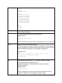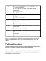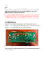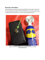
1
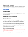
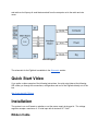
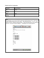
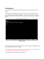
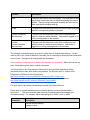
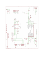
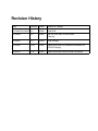
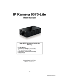
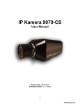
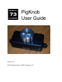
PigKnob User Guide Version 1.0C © 2013 Nicholas Garner, N3WG, Pignology, LLC Table of Contents Document Overview Copyright Notice Terms of Use and Liability Waiver Community Support Introduction PigKnob Device Overview Theory of Operation Quick Start Video Installation Ribbon Cable Power RS232 Rig Connection PigKnob Configuration Terminal Connection Configuration PigKnob Operation JP3 DTR/RTS Keying Encoder Lubrication Schematic PigKnob PCB Revision History Document Overview This document serves to guide PigKnob users through the use of the system. The perspective of this guide is from the point of view of a user who has just unpackaged the device. To start, we’ll cover the various components involved in the system. Copyright Notice PigKnob, Copyright © 2013 by Pignology, LLC.. All rights reserved. Terms of Use and Liability Waiver Terms of Use This product is offered to you conditioned upon your acceptance without modification of the terms, conditions, and notices contained. Use Limitation You may not modify, copy, distribute, reproduce, publish, license, create derivative works from, or sell, any information, software, products or services obtained, from the Pignology, LLC website or its products. Limitation of Liability In no event shall Pignology, LLC be liable for any direct, indirect, punitive, incidental, special consequential damages whatsoever arising out of or connected with the use or misuse of it’s products. General This disclaimer statement is governed by the laws of the State of California, USA. You hereby consent to the exclusive jurisdiction and venue of the Courts of competent jurisdiction, USA, in all disputes arising out of or relating to the use of this product. Use of this product is unauthorized in any jurisdiction that does not give effect to all provisions of these terms and conditions, including without limitation this paragraph. Modification of Terms and Conditions Pignology, LLC reserves the right to change the terms, conditions, and notices under which their products are offered. Community Support A Yahoo Group has been created for PigRemote. Please consider joining the group to receive information about updates, ask questions or report problems. If you know the answer to a question posed by another user, please feel free to help out. PigKnob Yahoo Group Introduction PigKnob is a remote tuning knob for amateur radios that use a plain text CAT protocol for rig control such as Elecraft, Kenwood and newer Yaesu radios. This document gives an overview of the device and its operation. PigKnob Device Overview Theory of Operation PigKnob is a remote tuning knob. It has 8 tactile switches and an optical rotary encoder with builtin switch. The device is controlled by a Microchip PIC18F26K22 running off 5 volts supplied by an internal LDO voltage regulator. TTL <> RS232 level conversion is facilitated by a MAX3232 IC. There are two boards connected by 6 conductor ribbon cable with RJ12 connectors on each end. The smaller board contains the two serial connections and power jack. The reason for the separate interface board is to reduce the number of cables coming out of the back of the device. The ribbon cable can be replaced by standard 6P6C silver satin phone cord if you need to increase the distance between the two boards. Each function on the device (switches and knob rotations) can be user configured to output a plaintext string of ASCII characters to the radio. NOTE: Radio’s that do not use a plaintext CAT control protocol such as the older Yaesu FT8X7 and Icom radios will not work with this knob. There are two serial ports on the PigKnob interface board. One for a computer and one for an amateur radio. The PigKnob allows you to connect the PigKnob inline between the computer and radio as it will proxy all serial data received from the computer out to the radio and vice versa. Block Diagram The schematic for the PigKnob is available in the Schematic section. Quick Start Video If you prefer a video example of the following instructions, the quick start video at the following URL walks you through the connections, configuration and use of the PigKnob directly out of the box. http://youtu.be/uU8_78j3pqc Installation The system is on or off based on whether or not the power supply is plugged in. The voltage regulator accepts a maximum of 15 volts input with a minimum of 7 volts. Ribbon Cable The ribbon cable between the main board and the satellite interface board should be connected first. The power from the power supply is carried on this cable to the main board. The satellite interface board is not in an enclosure as it’s expected to hang behind your desk, out of sight. There are 4 large holes in the PCB allowing for cable ties to be used if you wish to attached the board to something. Take care not to short any of the pins on the bottom of the PCB. Power The supplied power cable has bare leads on one side and a 2.1mm ID, 5.5mm OD barrel connector on the other side. The wire with the white stripe is positive. When the device is plugged in, it is on. RS232 Rig Connection The RS232 rig connection is the male DE9 connector on the satellite interface board. It is wired as a DTE Device. The connection from this port to your radio will be based on the connection options of the radio. For example, for an Elecraft K3 you should use a standard straight through serial cable. For the Elecraft KX3, you would use the Elecraft KXSER cable. RS232 Computer Connection The RS232 computer connection is the female DE9 connector on the satellite interface board. It is wired as a DCE Device. A straight through serial cable should be used to connect this port to the computer. PigKnob Configuration Every physical function (switches and encoder spins) on the PigKnob can be configured. The configuration of the PigKnob is accomplished through the computer serial port on the satellite interface board. NOTE: While in config mode, all data received on the computer serial interface on the interface board is interpreted as a config command and will not be proxied over to the radio. If the LED is blinking, the device is in config mode and your rig control software will not be able to control the radio through the PigKnob. Terminal Connection Using a standard terminal emulator such as TeraTerm on Windows, or Minicom on Mac/Linux. Open the COM port connected to the PigKnob with the following settings. Default Serial Port Configuration Parameter Default Setting Baud 38400 Data Bits 8 Parity None Stop Bits 1 NOTE The serial library in use on the PIC MCU sends nulls (0x00) following a write. Some terminal emulators display these nulls for some reason. They might show up as “.” or “<0>”. If you experience this, try a different terminal program. Those mentioned above do not experience this issue. CoolTerm on Mac will display a “.” as displayed in the following picture. Configuration Once you have the connection up, press “$$$” several times to be presented with a “CMD>” prompt. The following image shows Minicom running in Terminal on Mac. The text above “CMD>” is what is displayed when the PigKnob is plugged in. You won’t see this unless you remove and reapply power to the PigKnob. After boot, “$” was pressed several times to get into command mode. Minicom on Mac When the PigKnob is in command mode the LED on the front of the device blinks rapidly. When not in config mode the LED is on, no blinking. NOTE: Spinning the knob while in config mode can have erratic results on the radio’s frequency. Exit command mode to test any changes to the knob commands. The following elements of the PigKnob can be configured. Function Description Baud The baud rate used on both serial ports. The baud rates on both serial ports must be the same to avoid overrunning the internal buffers. There is a single command to modify the baud rate on both serial ports (computer and rig). B1B8 The plaintext command that will be sent out the radio serial port when the corresponding button is pressed. Encoder Clockwise (fast and slow) The plaintext command that is sent out the radio serial port when the knob is rotated clockwise. Fast mode is toggled on or off by pressing down on the encoder. Encoder CounterClockwise (fast and slow) The plaintext command that is sent out the radio serial port when the knob is rotated counterclockwise. Fast mode is toggled on or off by pressing down on the encoder. The following commands can be executed in config mode to change/view settings. You will need to refer to the Owner’s Manual for the radio you’re controlling to determine what commands to put in here. Changes to the configuration are immediate. All commands are case sensitive, always use lowercase for commands. Macro text can be any case. Most radios ignore case of control commands. You should refer to the Programmer’s Reference for your particular radio when setting commands that are sent when buttons are pressed. For Elecraft, the E11 version of the Programmer’s Reference can be found here: http://www.elecraft.com/manual/K3&KX3%20Pgmrs%20Ref,%20E11.pdf The most up to date version of this Programmer’s Reference can be found here: http://www.elecraft.com/K2_Manual_Download_Page.htm#K3 For other radio’s, the control commands are usually in the User’s Manual. Please Note: In certain scenarios you may need to preface a macro command with a semicolon, ‘;’. This will ensure the radio resets its command buffer and interprets your command correctly. For example, rather than setting B1 to “MD1;” set it to “;MD1;”. Command Description p Print the current settings. Example output: CMD> p Settings: UART Baud: 38400 Buttons: B1: FA00014150000;MD2; B2: FA00014030000;MD3; B3: FA00007150000;MD1; B4: FA00007030000;MD3; B5: FA00003640000;MD1; B6: FA00003530000;MD3; B7: FA00010106000;MD3; B8: FA00018108000;MD2; Knob: CW: UP; FCW: UP4; CC: DN; FCC: DN4; h Print the help information. q Exit config mode and return to normal operation. Example output: CMD> q 73 de N3WG, Pignology, LLC BTU... NOTE: It will not return to the “CMD>” prompt when you quit config mode. FRFR Reset the device to the factory defaults. NOTE: An alternative to this command is to hold down S1 while applying power to the device. Release the switch after about 2 seconds and it will reset the EEPROM contents to the as shipped configuration. Example output: CMD> Resetting to factory defaults, you don't need to restart. You might need to change baud to 38400. Defaults loaded CMD> r # Set baud rate for both UARTs. "#": 1=38400, 2=19200, 3=9600 Serial port parameters are fixed at 8N1. The microcontroller in the PigKnob doesn't support 2 stop bits. 38400 is the default Example output: CMD> r 2 Set UART baud 19200. NOTE: At this point you would need to change the baud rate of your computer’s serial port to start talking to the device again. b # <text> b# <TEXT> = Set macro button # to <TEXT>. Max length = 100. E.g. b1 FA00014060000;MD3; Use ` for CR and ~ for LF if needed. That's backtick and tilde. Example output: CMD> b1 KY BTU DE N3WG K; Set b1 command. CMD> cw <text> Set the text sent when the knob is rotated clockwise. Example output: CMD> cw UP2; Set encoder clockwise command. CMD> cc <text> Set the text sent when the knob is rotated counterclockwise. Example output: CMD> cc DN2; Set counterclockwise command. CMD> fcw <text> Set the text sent when the knob is rotated clockwise while in fast mode. Example output: CMD> fcw UP5; Set encoder fast clockwise command. CMD> fcc <text> Set the text sent when the knob is rotated counterclockwise while in fast mode. Example output: CMD> fcc DN5; Set encoder fast counterclockwise command. CMD> Make sure you “q”uit from config mode when you’re finished configuring the device so the encoder works properly and you can use your rig control software of choice through the PigKnob. PigKnob Operation Pressing of any switch or rotation of the knob on the device will immediately send the string of text stored in EEPROM out of the radio’s serial port on the interface board. When a computer is also connected to the interface board and the device is not in config mode, any data sent into the computer serial port on the interface board is immediately sent out the radio serial port to the radio. This allows you to run a rig control software package on your computer while still using the PigKnob. JP3 There is a jumper on the satellite interface board. When this jumper is shorted, pins 7 and 8 on the radio serial port are looped back into each other. This allows you to use the device with radios that require hardware flow control such as Kenwood transceivers. This is not true hardware flow control, it is simply faking it to the radio. NOTE: DO NOT HAVE THIS JUMPER CONNECTED AND CONNECT TO AN ELECRAFT K2. YOU WILL HURT THE RADIO; THE K2 DOES NOT HAVE STANDARD RS232 SIGNALS ON THE KIO2 MODULE. WHEN IN DOUBT, DON’T USE THIS JUMPER UNTIL YOU VERIFY IN THE RADIO’S MANUAL THAT IT’S WHAT YOU NEED. DTR/RTS Keying The first iteration of the PigKnob only passes pins 2 and 3 through to the radio from the computer. If you are using a contest type software package, like WinTest, that has the capability to do PTT and Keying using the DTR/RTS signals this will not work without a hardware modification to add jumpers between pins 4 and 7 on the interface board. Interface Board Mod for DTR/RTS Keying The next revision of the PigKnob will most likely have a DIP switch that can be closed to connect these signals. Encoder Lubrication After prolonged use, the optical encoder used in the PigKnob can start to stick. This is due to the friction caused by the encoder shaft rubbing against the wall, the lubrication added by the encoder manufacturer can diminish. A quick shot of WD40 onto the shaft will loosen it back up. The manufacturer of the encoder, CUI Inc., has confirmed and approved this fix. Remove the knob with a 5/64” allen wrench Apply a small amount of WD40 (or equivalent lubricant) to the shaft. Clean off the excess. Schematic PigKnob PCB Revision History Date Version Author Reason for Change 2013042020130425 0.1 N3WG Initial Draft 20130429 0.2 N3WG Add YouTube URL for Quick Start Clean Up 20130501 1.0 N3WG Initial Release 20130526 1.0B N3WG Added information on hardware modification for DTR/RTS keying. 20140121 1.0C N3WG Added information about encoder lubrication.