1
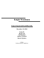
Knight Watchmen Project Proposal and Feasibility Study December 10, 2004 Team #1: Brian Netz Jeff Shumate Andrew Tazelaar Derek Wykstra Advisor: Professor Steven H. VanderLeest 1 Table of Contents Table of Contents .......................................................................................................................... 1 1. Introduction........................................................................................................................... 2 2. Our Team............................................................................................................................... 2 2.1. Brian Netz ...................................................................................................................... 3 2.2. Jeff Shumate .................................................................................................................. 3 2.3. Andrew Tazelaar........................................................................................................... 3 2.4. Derek Wykstra .............................................................................................................. 3 3. Design Norms ........................................................................................................................ 3 3.1. Cultural Appropriateness ............................................................................................ 3 3.2. Transparency................................................................................................................. 4 3.3. Stewardship and Caring............................................................................................... 4 3.4. Integrity ......................................................................................................................... 5 4. Task Specifications ............................................................................................................... 6 5. Design Alternatives ............................................................................................................. 11 5.1. Deterrent...................................................................................................................... 11 5.1.1. Water Hose .............................................................................................................. 11 5.1.2. Noise Deterrent........................................................................................................ 12 5.1.3. Focused Beam of Light ........................................................................................... 12 5.1.4. Paintball Gun .......................................................................................................... 12 5.2. Tracking/Detection ..................................................................................................... 13 5.2.1. Ultrasonic............................................................................................................. 13 5.2.2. Thermal Imaging ................................................................................................ 13 5.2.3. Video Camera/Webcam...................................................................................... 14 5.2.4. Passive Infrared (PIR) Sensors.......................................................................... 14 5.3. Motion .......................................................................................................................... 14 5.3.1. Stepper Motors.................................................................................................... 14 5.3.2. Motor and Actuator............................................................................................ 14 5.3.3. Pan/Tilt Controller.............................................................................................. 15 6. Analysis of Alternatives...................................................................................................... 15 6.1. Deterrent:..................................................................................................................... 15 6.2. Tracking: ..................................................................................................................... 16 6.3. Motion:......................................................................................................................... 16 7. Design................................................................................................................................... 17 8. Method of Approach........................................................................................................... 18 8.1. Future Task Delegation .............................................................................................. 19 8.1.1. Brian..................................................................................................................... 19 8.1.2. Jeff ........................................................................................................................ 20 8.1.3. Andrew................................................................................................................. 20 8.1.4. Derek .................................................................................................................... 20 9. Time Schedule ..................................................................................................................... 20 10. Cost Estimate....................................................................................................................... 21 10.1. Prototype.............................................................................................................. 22 10.2. Production ........................................................................................................... 23 11. Feasibility............................................................................................................................. 24 12. Conclusion ........................................................................................................................... 25 2 1. Introduction As senior engineering students at Calvin College, we are tasked with bringing a product from the very first brainstorming session through to final prototyping, testing, and documentation. With this aim in mind, we propose a device to deter deer and other animals from gardens and yards. This document is a study of our project, analyzing how we got to this point, describing the current design, and reporting on the feasibility of actually accomplishing this task. 2. Our Team Figure 1 Team # 1 Andrew Tazelaar, Derek Wykstra, Jeff Shumate, Brian Netz Consisting of three men with an electrical concentration and one with a mechanical concentration, we are Team #1: The Knight Watchmen. Our generic initial idea revolved around creating a tracking system of some sort, an idea which was refined to our current project when Professor Nielsen proposed a system to help keep deer out of his backyard. We hope that our varied backgrounds and mixed concentration team will allow us to creatively solve problems and develop an effective, intuitive design. 3 2.1. Brian Netz Brian is twenty-one and was raised in Pella, Iowa and found himself at Calvin College when he followed his high school sweetheart. This past summer he married that sweetheart and worked for Beta Integrated Concepts doing controls engineering. Brian currently has no definite plans after school and is open to grad school or fulltime employment. 2.2. Jeff Shumate Jeff is twenty-one and was born in Grand Rapids, Michigan, where he has lived his entire life. He is engaged to Meghan Reeves who he met here at Calvin College and will be getting married in April, 2006. Jeff plans to work upon graduating and is currently searching for a suitable place of employment. 2.3. Andrew Tazelaar Andrew was born in Palo Alto, California, but has spent most of his life in Rochester, Minnesota. He is twenty-one and the lone mechanical engineer on the team. After graduation, he hopes to pursue a career in either the aerospace or automotive industry. 2.4. Derek Wykstra Derek is twenty-one and grew up in Martin, Michigan – a small town of 500 residents. He will be getting married this summer and currently has a job offer at Apex Controls, Inc. in Hudsonville, MI, where he will be pursuing a full time career as a controls engineer. 3. Design Norms When designing any product or device, it is imperative to consider both the values put into the design itself and the values of the end users of the product. Discussed here are the values and norms we believe are important to our project 3.1. Cultural Appropriateness Any design must fit into the culture and setting of its intended user. In this case, we are targeting consumers who not only have gardens and yards, but also have trouble with animals invading and destroying those spaces. This implies that they place a value on the aesthetics of their yard and 4 garden, and are concerned about preserving those aesthetics. Consequently, our design cannot be visually intrusive. Typically these consumers are also going to be environmentally conscious, as such, even though they wish to remove the animals from their yards, they will not want to injure or otherwise disturb the animals. This is one of the main reasons we decided to do away with the paintball gun to focus on water. Paintballs travel at very high rates of speed and consequently can be very dangerous, particularly to smaller creatures. As our device is going to be based heavily around technology and electronics, it is important that our market be accepting of technology. We believe this to be the case, as automatic sprinkler systems are common among gardeners and homeowners, and our project is something of a natural extension of those systems. Superseding the requirements of the end user are the laws by which we all must live. Researching laws and ordinances of the Grand Rapids area, we found that within most cities it is illegal to fire not only a paintball gun, but anything that might possibly be defined as a projectile. This again steered us away from the paintball option as well as preventing us from considering any other sort of projectile barring water. 3.2. Transparency People have to be able to understand how to not only operate our device, but also store, maintain, and possibly even repair it. With this in mind, our project should be intuitive enough that the user is only required to plug it in without extensive requirements for placement or location. We will be including a user’s manual for more specific information and use diagrams to allow for non-English speaking consumers. It should not interfere with the user’s yard and lifestyle, either through excessive amounts of equipment, imposing size, noise, or other factors. 3.3. Stewardship and Caring Stewardship is another key design norm to be considered. As Christians we should have a stronger calling towards this norm than the world might have as we are specifically called by God to take care of the creation He made as it says in Genesis 1:28 [NLT]: God blessed them and told them, "Multiply and fill the earth and subdue it. Be masters over the fish and birds and all the animals.” We have put a significant amount of time into looking over alternatives and analyzing our final choices to make sure that our project was very environmentally friendly through the use of a natural deterrent in water. 5 The initial design of a paintball gun had raised some flags regarding this as paintballs, though biodegradable, raise issues regarding the safety and health of the animals. This part of current design is especially well suited for this as not only will it be an effective deterrent, but it will deter in a way that is non-toxic and can even be beneficial, watering the users’ yard while keeping the animals out. Our design is also designed for very user-safe operation. With safety features such as emergency stops, waterproof housing, finger guards, and low voltage, our design will not harm the user in addition to being safe for use in the environment and on the target, making for a very non-offensive design. Our design will help reduce tension between homeowners and animals by deterring animals in a way that will not injure or kill the animals. Some homeowners decide to protect their gardens and yards by simply killing any offending animals; with our design we hope to promote a non-lethal solution. 3.4. Integrity To be marketable and more importantly to use good Christian design, our product should be highly dependable, in that it will not break down and that it will need little to no maintenance by the owner. It also should not become obsolete in a short amount of time. Some products, particularly computer technology products become obsolete within a couple years of being introduced, and the owners are forced to upgrade to stay current. However other products, such as cars, have a much longer useful life. Their values decline steadily, but they stay useful for many years. We aim to make our product have enough staying power that it can be used for years without needing to be replaced. The processor we choose will be fast enough to run our tracking software, and since it will be the only program running, the processor will not need to be upgraded in order to accomplish more or different tasks. The relationship between neighbors was also considered as we did not want our design to create tension between neighbors. Loud noises, large designs, and large flashing lights were quickly ruled out in order not to produce undue problems between neighbors. Similarly, the design needs to be inconspicuous – in that it is not an eyesore to the owners or neighbors and that it does not annoy people nearby through loud noises during operation - so as not to disturb the peace. 2.5 Personal Integrity Another important aspect of our project is personal integrity among our team members. In order to design a product that properly reflects our Christian faith and fulfills our other design norms, each of our members will need to have personal integrity. This means being willing to negotiate when opinions differ, do the work we are supposed to do on time, and help each other out when deadlines 6 need to be met. Primarily we need to remember that we are not designing a product for personal gain or prestige, but to reflect the gifts and talents given to us by God, and that everything we do in this project is a reflection of the person he made us. 4. Task Specifications Our task specifications include a list of what we need to accomplish, an estimated time limit, and a short description of the task. • Preliminary Feasibility Evaluation: (1 week) This evaluation is a critical examination of our project to determine if we are capable of completing it. • Preliminary Budget: (3 days) This is a proposed budget based on our initial research of the parts we will need to purchase to create the prototype. • Preliminary PPFS Report: (2 weeks) o Write First Draft: (1 week) This report contains the culmination of all of the different documentation we have so far. It reports our research results and the feasibility of our project. o Revise: (1 day) Check and fix any mistakes and expand on any portions that are less than properly reported. • Final PPFS Report: (2 weeks) o Revise Preliminary: (1 week) Re-check and re-write any sections that have proven inadequate, and make sure all aspects of the project are properly explained. o Assemble Final Report: (1 day) A final review of the last document for Engineering 339, which will then be submitted upon completion. • Research: (2 months) o Motors: (1 week) This will involve investigating which type of motor will be best to use for our entire assembly unit and also for our water hose. We will also determine properties of AC and DC motors to help in decision making for final design. o Gears: (1 week) This will entail researching how to reduce rotational speed as well as changing from rotation around a horizontal axis to rotation around a vertical axis. o Electrical Components: (2 weeks) Here we will be looking into what components work best and how to connect all them electrically. Power Supply: (2 days) Here, we will investigate the best voltage rating to use for supplying power to our system. Also, we need to make sure that the supply 7 provides sufficient current for the types of relays to use, as well as the entire rest of the circuit. The power supply also must be able to handle the voltages that are needed for specific components. Relays: (1 week) This research will involve investigating what type of relays should be used. Also, results from the research on power supplies will be necessary to determine how the relay is tripped. Parallel Port: (1 day) This will provide information such as the number of pins we have available. Also, a circuit is necessary to ensure that current is regulated and does not overload that processor. Opto-Isolator Circuit (1 day) In researching the parallel port, we determined that we needed a circuit for surge protection. This research will help in the design of that circuit. Water Solenoid: (1 day) Here we will look into the proper dimensions for the electronic valve. Values such as operating voltage and current are necessary for integration with the overall system. o Framing Material: (1 week) This will be an investigation of what type of material will be best suited to construct the prototype and production designs. Factors to be considered will be weight, aesthetics, strength, etc. o Nozzles: (1 week) Here we will determine what type of nozzle will give us the best distance and accuracy. • Control Code: (3+ months) o Tracking System: (3 weeks) This portion of the code will be one of the larger and difficult parts to write. It will be what tracks an object in the cameras field of vision and relays a position to the rest of the program, and eventually to the pan/tilt controller. Video Input: (1 week) This will be the code that takes the video signal from the camera and recognizes it as such, and creates the bitmaps for processing. A very basic code was acquired from Joel DeVries which we will be adapting and expanding to meet the needs of our project specifications. Tracking Output: (1 week) The program will use this part of the code to output the position of the object Image Processing: (2 weeks) This is the part of the program that takes the captured bitmaps from the video input and processes them to find the moving object in the camera’s field of vision. 8 o Automatic Nozzle Control: (2 weeks) Here is where the program will control the pan/tilt module and aim the water nozzle. Input From Tracking System: (1 days) This is where the tracking system tells the valve to open. Motion Control: (2 weeks) Here the program will take the output signals from the tracking code output and uses them to aim the pan/tilt module in order to aim the nozzle in the proper direction. o Manual Control (Secondary Goal): (2 weeks) We would like to be able to manually control the aim of the nozzle independent of the program, but that is a secondary goal for us. The ability of manual control allows testing of the motor and spray unit independent from any code. If something is not working properly, this is a quick way to test if it is a tracking code problem or a motor problem. This testing is most useful for prototype but could also be beneficial for the end user as well. Input From User: (1 week) This would be the input from either a game port using a joystick or from the keyboard, whose signals would then be processed and sent out. Output to Motion Control: (1 week) Here is where the input from the user would be output to the pan/tilt module and move the water nozzle: Output to Water Solenoid: (1 day) This is what the user would use to actually spray an object, which will be just a simple signal activated by a key/button. o Visual Interface: (1 weeks) This will be for the purpose of testing our prototype. We will be able to see what the camera sees and where the cursor is pointing. With that information as well as watching where the nozzle is spraying, we will be able to determine how well our tracking code is working. o Fixture Control: (2 weeks) This is what the program will use to take input from the motion sensors and move the fixture with the nozzle and camera to face the direction of the moving object. Input From Sensors: (1 day) Here is where the motion sensor input will be read and translated into a direction, which is where the fixture will then move. Output to Motion Control: (2 weeks) This is what the program will use to output the direction the fixture should be facing to the motor, which will spin the fixture to face the intruding object. • Power Circuit: (2 months) The power circuit contains all of the electrical components that will be used for protection and the actual wiring from computer to the different components. 9 • Water Valve: (2 weeks) o Electrical Wiring: (1 week) This includes the wiring and electrical testing of the valve that will turn the flow of water on and off. o Physical Assembly: (1 week) This is where we will actually attach the water solenoid to the fixture and test the motion of the pan/tilt module with the solenoid attached. • Base Design/Build: (1 month) o Assembling Motor & Gearing: (1 week) This is where we will assemble the motor and gearing into a housing which will then be mounted to the frame of our prototype. o Primary Frame: (2 weeks) Here is where we will assemble all of the different components of our frame, such as legs and motor/gearbox into a single, standing frame. o Attachment Frame: (1 week) This is when we will assemble and attach the frame that will hold our pan/tilt module and our water nozzle, as well as our camera. • Electrical Wiring: (1 month) o Initial Wiring: (2 weeks) Here is where the time will be spent taking all of our individual components and wiring them together and giving them all power wires, so that we can begin to run our prototype. o Testing: (2 week) Here is when we will test all of the electrical components to ensure that they are wired up correctly and that they function properly. • Final Integration: (1 month) This is where we will spend our time integrating all of our separate components, such as our motion detectors, our pan/tilt module, our water solenoid, our fixture motor, and our code. We will spend this time trying to make everything work together properly and make the overall system function successfully. o Base: (1 week) This will entail the attachment of the pan/tilt motor to the base of the device. The motion sensors will also be attached in this stage. o Panel: (1 week) The panel contains all of the electrical components. In this stage all of those components will be securely placed within the panel. The parallel port connection for our prototype will be connected to that as well. o Hose/Nozzle: (2 days) Here, the nozzle will be attached to the pan/tilt motor. Also included in this stage is the connection of the hose to the water solenoid. • Ordering Parts: (2 weeks) We expect to spend a little time selecting specific parts and a vendor where we can purchase or borrow from. Upon receipt of our ordered parts there will be a quick inspection to ensure that we have the right parts and they are working properly. • Documentation: (1- 2 months) Documentation requires a lot of time that could be used in a more useful matter. It’s always good to ask “Am I doing the right thing?” instead of, “Am I doing this 10 right?” Various documents are required from us during this year which includes: status reports, budget reports, hours, feasibility studies, and other reports. These reports are finished for this semester, but there will be many for next semester as well, although we do not know what they are yet. • Testing: o Water Solenoid: This device will be tested to ensure that it opens and closes properly as well as help us understand how it works. o Assembly Motor: The assembly motor moves the entire unit from facing one direction to facing another. It needs to be tested for speed to make sure it doesn’t spin too fast. Also we need to make sure it is accurate and smooth in transition. o Pan/Tilt: The pan/tilt motor needs to be tested so we understand how the motor operates. This information will be helpful for programming the right inputs so it behaves as we need it to. o Base Sturdiness: We need to make sure that the base is sturdy enough that it doesn’t fall over. Forces of wind and physical blows need to be checked to ensure it will stay up. o Sensors: The sensors need to be tested to make sure they are working. Also, we need to understand what signal is a result of the motion sensor being activated by motion. o Automatic Tracking Code: As the code increases in complexity to meet our needs, we need to make sure that it still functions as it needs to. o Manual Control: When the manual control code is developed we need to make sure it works properly and that it doesn’t fail in any aspect. o Overall Integration: Once everything is put together we need to test for a few various elements. We need to make sure that it tracks and sends signals properly. The emergency stop will be checked. 11 5. Design Alternatives During the research stage of our project we looked at different ways to accomplish the various tasks of the problem we set out to solve. Our design can be broken into four main parts that we have alternatives for: deterrent, tracking/detection, control/processing, and movement. A numerical breakdown of these options can be seen in the decision matrices of the next section, Analysis of Alternatives. 5.1. Deterrent The deterrent component to our project had the most diversity as there are many different ways to motivate animals to leave an area. Throwing away unworkable and impractical designs, our best alternatives for deterrent are: 5.1.1. Water Hose Currently our primary design, this consists of an ordinary water hose that attaches to any exterior household faucet that will be turned on to spray the intruder. There are many advantages to this option, first and foremost of which is safety. A typical garden hose, even fully open, is not powerful enough to harm any animal large enough to trip the motion sensor. Sprinkler systems are used by nearly everyone with a yard and garden, and such water velocities and pressures are commonplace. At the same time, a hose is going to be powerful enough to provide a deterrent. Similarly, water as ammunition is in ready supply and is environmentally friendly. Being similar to automatic sprinkler systems which routinely run at night, it is low noise and could easily be run without disturbing neighbors. There are a few cons, though, including the possibility of erosion and runoff from the water stream. It could also be considered wasting water to deter the animals. The system also has a limited range and accuracy, as a household hose is not going to have enough pressure to reach an entire yard. Also, the farther the system does reach, the more the stream will disperse and the less effective it will be. The use of water also prohibits cold weather operation, although this is somewhat offset by the fact that there aren’t usually plants that need to be protected during the winter. 12 5.1.2. Noise Deterrent This would involve setting off a loud noise in order to scare the animal away. This is a very environmentally friendly option as there are no resources being consumed by the unit barring a small amount of electricity, and as there is no projectile besides some sound waves, the animals will not be harmed in any way. It would be extremely cheap, have a very long range, and also very simple to implement. However, this option has several problems. First and foremost, as sound is (mostly) unidirectional, it completely eliminates the need for any kind of a tracking system. Tracking being a primary focus of our project, this makes noise a poor choice for our purposes. Even without that, there are some other problems with it. Setting off a loud noise is technically noise pollution; any loud sound generally is unappreciated in a suburban setting, particularly at night. Even if there are no neighbors nearby the yard where it is being used, it is still liable to annoy the people living in the house, waking up children, interrupting conversations, or any other quiet activity. 5.1.3. Focused Beam of Light This option would use a high powered spotlight to focus on and deter the animals, possibly either with continuous beam or a pulsing action. This would be extremely environmentally sound, with no projectiles or use of ammunition. It would be completely quiet, with no moving parts besides a few small electric motors, yet still be fairly accurate and have good range. There are a few major downsides, however, primarily that it would be completely ineffective during the day or even at night in a well-lit area. It is also possible that the animals could get used to the light or simply not be affected by it enough to leave, or, as demonstrated by the ‘deer in the headlights’ syndrome, be too scared to even move at all. 5.1.4. Paintball Gun Initially our primary option, this would use a commercially available paintball gun to deter the creatures. The pros of this are that it would be extremely accurate, have a very long range, and be a very effective deterrent. It also has some extremely large cons. The two primary reasons that we abandoned this option are safety, and that it is illegal to fire a paintball in nearly all cities, eliminating a very significant portion of our perceived customer base. To put it simply, paintballs are not safe as they travel at a very high rate of speed and fairly likely do injure not only animals but also any humans that may enter the detection area. This is a major problem and 13 would have violated several or our design norms. Also, paintballs would leave unsightly residue and pieces behind, and although the balls themselves are biodegradable, the soapy water used inside of them would be somewhat polluting. 5.2. Tracking/Detection The tracking/detection part of our project had some interesting possibilities, but due to financial reasons, most of them were infeasible. 5.2.1. Ultrasonic Similar to a radar system, ultrasonic waves are shot out and bounce off of the objects to detect if anything is there. It would be very good for providing the range to the target, however, without an extremely complex network of them, it would be extremely difficult to track with. As the sensors return only a distance and not a direction, a large number of sensors would be required to provide not only a location but also distinction between multiple targets. This increases not only the cost, but also requires exact placement of the sensors, adding complexity to the end user’s usage, something we wish to avoid. Another negative is that the waves require a surface perpendicular to their direction of travel in order to be properly reflected back to the detector in order to register the presence of an object. An animal would have to stand at just the right orientation for the system to work. Not only that, but (similar to carpet) the fur on an animal will absorb some of the sound waves, weakening the signal even further. Even with multiple sensors, programming the system to properly identify targets based on varying positive and negative returns adds an incredible amount of complexity to the system. 5.2.2. Thermal Imaging Using a thermal camera to actively detect the heat given off by warm bodies would be a very effective way to pick up only animals or people, and would be the ideal solution, however, the costs for these cameras run into the thousands of dollars, making them extremely cost prohibitive for our purpose. In their favor, they would be very easy to track with and would work equally well during the day or night, though they would be difficult to determine range with. 14 5.2.3. Video Camera/Webcam This is currently our primary tracking/detection option. Using a video camera provides most of the benefits of the thermal imaging system at an extremely small fraction of the cost. They track extremely well and with a camera capable of picking up infrared radiation, will work at night as well as during the day. Using a webcam means that the images produced can easily be sent to computers in a standard format and thus can easily be used by the tracking software. It does carry the disadvantage of difficult range determination as with the thermal system. 5.2.4. Passive Infrared (PIR) Sensors Commonly used on exterior lightning, these sensors detect changes in infrared radiation. They are low cost, reliable, and perfectly suited for outdoor use. The major downside is that they do not provide any kind of tracking or range capabilities; they merely detect the presence of motion, or, more accurately, the presence of an infrared radiation source. As such, we have chosen to use them for just that, detecting the presence of an animal in a certain direction and then using this information to turn the nozzle assembly. 5.3. Motion Our project has two main sections of movement; the part that connects to the deterrent to aim it at the desired object and the motor to control the movement of the whole base. Only the former will be analyzed as we have determined the other options for the base would remove the tracking requirement and not allow us to obtain the accuracy we are looking for in the system. 5.3.1. Stepper Motors These would be an excellent solution due to their small size and high efficiency; however, given the power of the motors we would need they become prohibitively expensive. They are also very accurate and can be precisely controlled, which would be perfect for the tracking application that we have. Unfortunately, the costs truly are prohibitively expensive and are therefore not suitable. 5.3.2. Motor and Actuator This option would use one electric motor for rotation and a small linear actuator for vertical motion. This is an excellent option with regards to cost and speed, with motors and actuators 15 both being fairly quick and inexpensive. The major downside is that it would require a much more complex base and control system to be used, adding programming difficulty that would be beyond the scope of this project. Control would also be a major problem, as the electric motor would lack the precision speed changes needed for the tracking system. 5.3.3. Pan/Tilt Controller This is our primary motion control option, a security camera style pan/tilt controller. These units are ideal for our purposes as tracking is essentially their designated purpose. They are high precision, compact, and already integrate 2 axis motion into the unit. Many units are also weatherproof and designed to be controlled remotely right out of the box. 6. Analysis of Alternatives Throughout the process of research and design it is imperative that we compare different options in order to come out with the best result for this specific senior design project. The best way in which we were able to make these comparisons was to form a design matrix. The following matrices were used to determine the best possible solution: 6.1. Deterrent: 16 6.2. Tracking: 6.3. Motion: For all of these design matrices, the headings stand for: • Prototype: how easy/beneficial it’ll be for us to use for our prototype. For example if we have a donation for that specific item, the point value for it will be very high as we will not have to purchase or make that item. • Safety: scare the target in a way such as to not permanently damage any part of them such as their eyes, ears, or body. Also how well the approach prevents the user from harm. • Efficiency: to what fullness the approach accomplishes the desired task. • Versatility: how well it operates in many different conditions such as: rain, wind, and thunderstorms. • Reliability: how long the apparatus will be able to work at nearly 100% operating level under the conditions we have set for the product. • Ease of Integration: how easily it will adapt to our specific project, and how easily it will be for us learn how to use it. • Environmental Impact: how well it uses resources and does not harm the environment. • Neighbor Happiness: how our project will affect the mood of the user and surrounding neighbors. 17 • Accuracy: how accurately the motor can be positioned. • Speed: how fast the motor can move. • Tracking Precision: how precisely the device can track an object • Range Determination: how well the device can determine an object’s distancem Using this method we were able to decide that using the hose, the camera, and the pan/tilt controller would be the best choices for our project. The design for the stand of the apparatus has not been fully decided yet. Our top two designs for stabilization are a tripod or a table with four legs. Some other considerations have been a single pole or some sort of system where the device hangs from a wire. These two were thrown out due to stability issues. The type of materials we are using for the construction have not been fully decided yet either. We will probably not have all water proof metal as that would become either expensive or will bring into question the durability of the structure. The final design will be painted as that will cover up any metal that would other wise be susceptible to rust. 7. Design Our current design (see Figure 2) consists of seven main parts: the stand, motor, base, pan/tilt controller, water solenoid, motion sensor, and a camera. The water solenoid controls the flow of the water. This device sets on top of the pan/tilt controller that will point the water solenoid in the direction of the disturbance. The pan/tilt controller and the camera will sit on top of a platform that will be rotated by the motor. The motor will rotate this platform at 90° intervals depending on if a sensor has been triggered by motion. 18 Figure 2: Artist’s Representation of Final Design 8. Method of Approach Initially, our idea for a senior project was to develop a motion tracking system; however, we did not have any particular ideas for applications of it. During one of the early class lectures, Professor Nielsen proposed a device that would help keep deer out of people’s yards and gardens. These two ideas seem to mesh nicely and we decided to develop a motion-tracking deer deterrent. Once this was decided, we went about determining the best way to accomplish this. We began to investigate different methods for the various components, those pros and cons can be seen in more detail in the design alternatives section. We eventually settled on using a webcam for motion tracking, a pan/tilt controller for the motion control, and a paintball gun for the deterrent. After these first components were chosen, we began the initial design work. Through research and reaction to our initial design, it quickly became clear that although a paintball gun would likely be the most effective deterrent, it is not only illegal to fire in most cities, but also presents a plethora of safety problems and issues. We decided to scrap the paintball gun in favor of using water out of a hose, and have moved forward with that decision. Once the hose was chosen, the actual configuration of the device needed to be chosen. The primary idea had been a turret-style system, but the switch to water allowed for some more flexibility. The paintball 19 gun would have required a much more stable firing base for any kind of accuracy, and a much more complex firing system (compared to a hose nozzle) meant that the base would also have to be considerably more bulky. Using a hose opened the possibility of suspending the firing platform in the air, i.e. on the side of the house or hanging from a cable, and we even threw around the idea of making the platform mobile in order to cover a larger area. Finally, however, we decided to simply stick with the turret design, for several reasons. First, it will be much simpler for the end user to be able to place the device out in the middle of the yard or garden without having to install any hardware on the side of the house or string cable between two trees. Second, it allows for the device to be used anywhere there is a semi-level surface, and not just where it can be hung. Finally, adding mobility seemed as if it was going to add too much complexity and scope to the project, as we determined the primary focus of this was to make the motion tracking system work. That choice left us with a bit of a restriction however. Webcams have a somewhat limited field of view and would not be able to cover a wide area. We decided to connect motion sensors to the device that would detect an object in a certain area and be able to rotate the entire nozzle/webcam assembly toward the detected motion. Once properly situated, the camera would take over the tracking duty and more precisely direct the stream of water. Working with this set of design decisions, we have moved forward with our physical design. We have the wiring diagram for the device and have ordered some parts to begin assembling it. We are currently working on selecting a motor and gearing for the upper assembly, as well as selecting a pan/tilt controller. 8.1. Future Task Delegation In order to get our project done in a timely matter it is necessary to break down larger sections of the group into smaller tasks that can be done by one or possibly two people. We have decided to use the strengths of each of our team members to our advantage, as well as minimize the weaknesses of each by placing people on tasks that they feel comfortable and confident doing. 8.1.1. Brian Due to his background in programming classes and work experience, Brian Netz will be working mainly on the control code that will be installed on the PC that will run our prototype. As this will be the biggest and most challenging part, this is most of what he will be doing. He also will be 20 doing any 3D modeling or animations we may want for our presentations or documents. He will also be handling some of our documentation work. 8.1.2. Jeff Jeff Shumate will also be working mainly on control code because of his success in programming classes. Again, we feel that this will be the most challenging part of the prototype, and will take the most time and effort, thus we have decided to have two people make this aspect the primary focus of their work. He will also be the one checking and updating our schedule, and by telling the rest of the team if we begin to fall behind on any tasks. If this occurs, we will meet and decide who needs to do extra tasks or put in more hours to bring us back up to speed. 8.1.3. Andrew Andrew Tazelaar is the mechanical engineering student on the team and will be the one working on developing the gearing for our motor setup, as well as creating the design for the frame and fixture for the prototype. He will also be the one to head up the construction of these parts of the prototype, as well as helping with documentation. 8.1.4. Derek Derek Wykstra will be the one designing and assembling the panel layout to hold our electrical components (relays, power supply, etc.). He will also be working on assembling and testing the opto-isolator circuits that will be protecting the parallel port from overload when driving relays, as well as helping work on any documentation. 9. Time Schedule Once we had our task specifications, we were able to put together a schedule. The schedule was completed using Microsoft Project. The timeframe to complete each task was estimated and all predecessors linked together. We estimated long for many of the sections just in case we ran into problems. A Gantt chart showing that path of tasks gave us a clear idea where much of our efforts should be spent. This chart can be found in Appendix A. 21 There are two main sections to the project. The code and physical layout are the basic sections. Because of the nature of these two sections, there is a fair amount of float time from start to finish. Each section can be treated almost like a separate project until the very end when everything is put together. Neither the software nor physical assembly and layout affect the start time of the other section. We decided to divide our team so that two people work on the code and the other two do the electrical and mechanical aspects of the unit itself. Once we start coding and designing, there is continual testing until completion. Many of the sections are broken down to smaller and simpler sections for the purpose of testing. It is especially important to do this with the code. Once we have one block done, we add another until we finish with everything complete. During the times we meet as a group we make sure to maximize our time. Using the chart and task specs, we figure out what needs to be done over the given week. We divide up the weekly tasks to the person most experienced so that everyone is working as efficiently as possible. As we check our schedule every week, we can make sure that we are on task or if falling behind can take measures to catch back up. One thing we have is that we built a cumulative total of a few weeks of float time into our schedule, and our critical path is relatively loose. This means that if a few tasks take an extra week or two, it will not hurt our end date at all. Another advantage we have is that we have divided our tasks up effectively enough that each team member can keep track of their own part of the schedule, and if anyone is falling behind, we can all pick up a little slack and help pull ourselves back up to date. Finally, in some cases if we fall behind, simply putting more time in on a given day or week than we anticipated will be the best way to return to schedule. Simply put, if we fall behind, we will work harder to get back on schedule. 10. Cost Estimate We have very different cost estimates for our production cost versus our prototype costs. For our prototype cost, we are going to be able to pick up many parts free of charge through many channels, such as borrowing from our respective employers and using equipment that we own personally. This will help us keep our costs down for prototyping, but also skew our view of what a fully functional production version would cost if we were to use the exact equipment for production. For example, the panel we are 22 going to use is one designed for use with industrial machinery, and is far more expensive and tougher than what we would really need for a production model. This is being borrowed for use with our prototype and will be returned once we are finished with it. Although in balance with that, some of the equipment we are using, such as some of our relays and again, our panel, will cost much less for a production run because we will be using equipment not rated for industrial use, lowering the cost of those individual items. That combined with the fact that we would be mass producing these units and getting a good discount on parts means our production cost should be lower than the estimate we have now. We are unsure as to the costs of some parts for the production model because we are not sure about which parts would be best to use yet. Further research will be conducted into both parts and discounts, and better numbers will be finalized next semester. The costs we have compiled are laid out in the following sections. 10.1. Prototype This is a spreadsheet estimating our costs for the prototype being developed. Total estimated cost for this project is about $420 which is somewhat higher than our budget for the class. These costs are based on the fact that many of our more expensive items, such as the panel to house our electrical components and the relays to run our motor, are on loan to us from outside sources. However if we decide to use an embedded processor, we may have a substantial cost added to our existing costs. We are currently researching whether we should pursue this course of design or not. These items alone would increase our costs by at least a factor of 2, making our current design path infeasible without outside funding. Our biggest costs for prototyping will be the gearing we will need to allow our motor to properly rotate the fixture with our camera and water nozzle, the pan/tilt controller, which we will have to purchase, and the motion sensors, which are simple and commercially available. In the figure below, the notes help show where some of our costs are kept low and the sources for some of our parts. 23 Figure 3: Parts List and Price of Prototype Cost 10.2. Production For our production model, costs would, unfortunately, go up by over $100 to an estimated total of almost $550. This is due to the fact that many of the components we have free of charge for the prototype will need to be purchased for production, albeit at lower than retail cost. The prices we have estimated for our production model are based on a sales estimate of 100,000 units, and were garnered from online research and sources within the companies that have assisted us with part donations and equipment loans. One important note is that for our production model, we would no longer need a 24VDC power supply, because we would acquire a different type of relay and a different water solenoid and would no longer need the power supply. We would be using different components for production because there are other types of relays that are smaller and cheaper than those we have, and would use 120VAC for power. There are also water solenoids that run on the same 120VAC power that cost slightly more than the one we will use in the prototype, which would be cheaper than buying a power supply, and thus eliminate the need for one. The reason we are using the 24VDC power supply right now is that we were able to acquire the supply and the relays that use it without cost for use with our prototype, and the water solenoid that uses 24VDC is cheaper than one using 120VAC by about $5. 24 Another important issue is that our production costs are currently based on purchasing and assembling many components that would be integrated into a single production unit, such as many of our relays and our opto-isolator circuits. This would cut costs further, although this fact has not been figured in yet because we cannot get an accurate estimate as to which components would all be integrated or a good idea of what the cost of this integrated unit would be. Our estimated production costs have been laid out in the figure below, which gives an idea of why our costs for production are so much higher than our prototype costs. Figure 4: Parts List and Price of Production Cost 11. Feasibility With the research on motors and electrical components that we have done so far, we feel that our project is feasible and will get done by May 7, 2005. Andrew has conducted several calculations on our motor (see Figure 5) and has found that the motor that we are planning to use will be more than sufficient for 25 our immediate design. Derek and Brian’s prior knowledge of control systems should help the designing and implementation of the electrical circuit. We will be within our budget constraints with the budget that we have proposed, and do not foresee any other large expenses. Our greatest hurdles right now are getting the code working and the integration of all of the different electrical and mechanical components. Brian and Jeff are currently working on the code, and if they have any questions there are many coding development pages on the internet as well as Joel DeVries who wrote the tracking code. We are currently on schedule and we still have some float time if anything needs to be pushed a couple of weeks. Figure 5: Equations and Calculations Used for Assessing the Needed Torque 12. Conclusion This project is the combination of several different types of engineering and design, the merging of different concentrations. The success of the project hinges on the success of this integration. We have already overcome several boundaries to this integration, from developing a workable tracking system to the correct use of a parallel port to control the device. We have also overcome some more administrative issues, such as the elimination of a paintball gun for tracking and the substitution of water. More hurdles do stand in our way; however, we believe that we have the beginnings of solutions to them and that they do not represent fatal threats to the success of the Knight Watchmen. Figure A.1 ID Task Name Duration 1 Project Work 160 days Mon 9/27/04 Fri 5/6/05 1 wk Mon 9/27/04 Fri 10/1/04 2 Preliminary Feasibility Evaluation 3 Budget 4 Research Start Finish 3 days Mon 10/4/04 Wed 10/6/04 10 days Mon 10/4/04 Fri 10/15/04 Fri 10/8/04 5 Motors 1 wk Mon 10/4/04 6 Gears 1 wk Mon 10/4/04 Fri 10/8/04 7 Electrical Components 2 wks Mon 10/4/04 Fri 10/15/04 8 Frame Materials 1 wk Mon 10/4/04 Fri 10/8/04 9 Nozzles/Valves 1 wk Mon 10/4/04 Fri 10/8/04 10 Ordering/Acquiring Parts 2 wks Mon 10/18/04 Fri 10/29/04 11 Control Code 65 days Mon 12/6/04 Fri 3/4/05 30 days Mon 12/6/04 Fri 1/14/05 Fri 12/17/04 12 Tracking System 13 Video Input 2 wks Mon 12/6/04 14 Motion Tracking output 2 wks Mon 1/3/05 Fri 1/14/05 15 Image Processing 2 wks Mon 12/20/04 Fri 12/31/04 16 Automatic Nozzle Control 20 days Mon 1/17/05 Fri 2/11/05 17 Input from Tracking System 2 wks Mon 1/17/05 Fri 1/28/05 18 Output to Motion Control 2 wks Mon 1/31/05 Fri 2/11/05 15 days Wed 1/5/05 Tue 1/25/05 2 wks Wed 1/5/05 Tue 1/18/05 1 wk Wed 1/19/05 Tue 1/25/05 15 days Mon 2/14/05 Fri 3/4/05 2 wks Mon 2/14/05 Fri 2/25/05 1 wk Mon 2/28/05 Fri 3/4/05 10 days Wed 1/5/05 Tue 1/18/05 19 Manual Nozzle Control 20 Input from User 21 Output to Motion Control 22 GUI 23 GUI itself 24 GUI integration 25 Nozzle Assembly Motion Control 26 Input from Sensors 1 wk Wed 1/5/05 Tue 1/11/05 27 Output to Motion Control 1 wk Wed 1/12/05 Tue 1/18/05 35 days Mon 1/31/05 Fri 3/18/05 1 wk Mon 1/31/05 Fri 2/4/05 1.2 wks Mon 2/7/05 Fri 3/18/05 28 Water Valve Integration 29 Electrical Wiring 30 Physical Assembly 31 Base Design/Assembly 40 days Mon 2/14/05 Fri 4/8/05 32 Motor Asseblies 2 wks Mon 2/14/05 Fri 2/25/05 33 Primary Frame 2 wks Mon 2/28/05 Fri 3/11/05 34 Attachments 2 wks Mon 3/14/05 Fri 3/25/05 35 Assembly 2 wks Mon 3/28/05 Fri 4/8/05 36 Overall Integration 3 wks Mon 4/11/05 Fri 4/29/05 37 Testing 2.5 mons Mon 2/28/05 Fri 5/6/05 er 1 September 21 October 11 November 1 November 21 December 11 January 1 January 21 February 11 March 1 March 21 April 11 May 9/12 9/19 9/26 10/3 10/10 10/17 10/24 10/31 11/7 11/14 11/21 11/28 12/5 12/12 12/19 12/26 1/2 1/9 1/16 1/23 1/30 2/6 2/13 2/20 2/27 3/6 3/13 3/20 3/27 4/3 4/10 4/17 4/24 5/1 38 39 Administrative Work 153 days Wed 10/6/04 Fri 5/6/05 40 PPFS First Draft 10 days Wed 11/17/04 Tue 11/30/04 41 PPFS First Draft 1.5 wks Wed 11/17/04 Fri 11/26/04 42 Revise PPFS First Draft 0.5 wks Fri 11/26/04 Tue 11/30/04 7.5 days Wed 12/1/04 Fri 12/10/04 1 wk Wed 12/1/04 Tue 12/7/04 0.5 wks Wed 12/8/04 Fri 12/10/04 Fri 5/6/05 43 PPFS Final Draft 44 Continue PPFS Revising 45 Assemble Final PPFS report 46 Final Presentation 2 wks Mon 4/25/05 47 Poster Work 2 wks Mon 4/25/05 Fri 5/6/05 48 Final Report 1 mon Fri 4/1/05 Thu 4/28/05 49 Oral Presentation 1 1 wk Wed 10/6/04 Tue 10/12/04 50 Oral Presentation 2 1 wk Wed 11/24/04 Tue 11/30/04 51 Oral Presentation 3 1 wk Mon 2/7/05 Fri 2/11/05 52 Oral Presentation 4 1 wk Mon 3/28/05 Fri 4/1/05 53 Projects Banquet 1 day Mon 4/25/05 Mon 4/25/05 55 Refined Task Specifications 1 day Fri 10/29/04 Fri 10/29/04 56 Preliminary Project Schedule 1 wk Mon 11/1/04 Fri 11/5/04 57 Project Briefing 1 wk Mon 11/8/04 Fri 11/12/04 58 Documentation 2 mons Mon 3/7/05 Fri 4/29/05 59 Troubleshooting 2 mons Mon 3/7/05 Fri 4/29/05 54 Project: team 1 project.mpp Date: Fri 2/11/05 Task Progress Summary External Tasks Split Milestone Project Summary External Milestone Page 1 Deadline