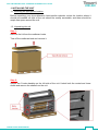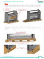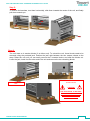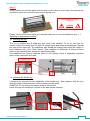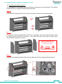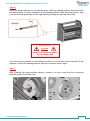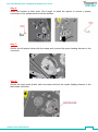
1
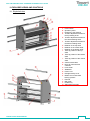
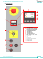
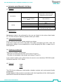
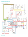
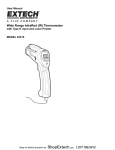
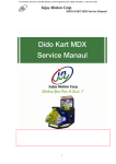
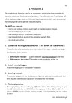
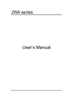
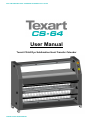
DYE SUBLIMATION HEAT-TRANSFER CALENDER Texart CS-64 User Manual Texart CS-64 Dye Sublimation Heat-Transfer Calender TEXART CS-64 USER MANUAL DYE SUBLIMATION HEAT-TRANSFER CALENDER Texart CS-64 Table of contents WARRANTY TERMS P.3 DECLARATION OF CONFORMITY P.4 1. INSTALLING THE UNIT P.5 1.1. Selecting an appropriate location 1.2. Unpacking the unit 1.3. Securing the unit 1.4. Installing the feeder tray 1.5. Installing the heating element P.5 P.5 P.8 P.8 P.9 2. CAUTION WHILE INSTALLING THE UNIT P.12 2.1. Power requirements 2.2. Installation 2.3. Safety provisions 2.4. Switching the unit off 2.5. Warning labels P.12 P.12 P.13 P.13 P.13 3. P.14 EXPLODED VIEWS AND CONTROLS 3.1. Exploded view 3.2. Operation panel P.14 P.15 4. P.16 ADJUSTMENTS AND RECOMMENDATIONS 4.1. Connecting to a power outlet 4.2. Setting the temperature 4.3. What to do after an emergency stop 4.4. Speed, feed direction (forward/reverse) and safety reset 4.5. Switching the unit off and cooling 4.6. Connecting an air purification filter P.16 P.16 P.16 P.17 P.17 P.18 5. MEDIA ROLLS, MEDIA PATH AND SPECIFICATIONS P.19 5.1. Loading media rolls and media path 5.2. Specifications 5.3. Loading media onto a self-locking shaft 5.4. Adjusting the media tension 5.5. Installing the self-locking shafts 5.6. Usable media and precautions P.19 P.20 P.21 P.21 P.21 P.21 6. RECOMMENDATIONS FOR MEDIA LOADING P.22 7. SPECIFICATIONS P.22 8. CLEANING, MAINTENANCE, DISPOSAL P.23 8.1. Cleaning 8.2. Maintenance 8.3. In the event of a failure 8.4. Replacing a mains fuse 8.5. Disposal P.23 P.23 P.23 P.23 P.23 9. ELECTRICAL WIRING DIAGRAM TEXART CS-64 USER MANUAL 2 DYE SUBLIMATION HEAT-TRANSFER CALENDER Texart CS-64 Warranty Your dye sublimation heat transfer calender is warranted against all manufacturing and material defects for a period of one year, starting on the date of purchase. The felt on the driving belt is excluded from this warranty. This warranty does not cover incorrect use of the unit. In the event of material or manufacturing defects, the unit shall be repaired either by the dealer where the unit was bought or returned to the manufacturer. There are no warranties other than those expressly set forth herein. This warranty does not cover incidental or consequential damages, whether foreseeable or not. If you believe your unit requires repair, be sure to mention your unit’s serial number, as this will be required to process your request. TEXART CS-64 USER MANUAL 3 DYE SUBLIMATION HEAT-TRANSFER CALENDER Texart CS-64 Declaration of conformity KALA S.A.S. Parc de l’Ecotay 35410 Nouvoitou France Declares that the following product: Texart CS-64 Dye Sublimation Heat-Transfer Calender complies with the following requirements: Voltage: 220~240V – 26A – 50/60Hz Machinery directive (2009): 2006/42/CEE, including: - Low voltage directive 2006 95 CE based on EN 60204-1 (2006) - Electromagnetic compatibility directive 2004 108 CE based on EN 61000-6-1 and EN 61000-63 (2007 edition). As a result of our continuous efforts to improve the product’s functionality, all specifications and product features mentioned in this document are subject to change without prior notice. TEXART CS-64 USER MANUAL 4 DYE SUBLIMATION HEAT-TRANSFER CALENDER Texart CS-64 1. INSTALLING THE UNIT 1.1. Selecting an appropriate location Before unpacking your dye sublimation heat-transfer calender, select the location where it should be installed: all side of the unit should be readily accessible, and there should be ample free space around the unit. 1.2. Unpacking the unit Step 1: Remove the lid from the cardboard crate. Tear off the cardboard end and remove it. Step 2: Secure the 3 brake handles on the left side of the unit. Unlock both the central and lower shafts and remove the shafts from the unit. TEXART CS-64 USER MANUAL 5 DYE SUBLIMATION HEAT-TRANSFER CALENDER Texart CS-64 Step 3: A wooden ramp is provided to help you unload the unit. Take it out of the crate by passing it through the two tension bars. Position the ramp’s edge flush against the pallet, as shown. Step 4: The unit is secured to the pallet by means of 2 metal brackets. These brackets are screwed to the pallet. Loosen the 4 nuts using a 17mm spanner/socket wrench and an 8mm Allen key, then remove the locking screws. TEXART CS-64 USER MANUAL 6 DYE SUBLIMATION HEAT-TRANSFER CALENDER Texart CS-64 Step 5: To remove the brackets, turn them horizontally, slide them towards the center of the unit, and finally pull them towards you. Step 6: The unit rests on 4 wooden blocks (2 at either end). To unload the unit, these blocks need to be removed using the provided jack. Position the jack right between the two casters closest to the ramp. Raise the unit until you can easily remove the 2 wooden blocks, and slide the blocks out. Lower the jack, install it at the other end of the unit and remove the two remaining blocks. Jack Raise the unit and remove the wooden blocks CAUTION THE JACK NEEDS TO BE LEVEL ON THE PALLET FLOOR AND MUST NOT SLIP OR SLIDE WHILE YOU RAISE IT TEXART CS-64 USER MANUAL 7 DYE SUBLIMATION HEAT-TRANSFER CALENDER Texart CS-64 Step 7: Slowly roll the unit from the pallet onto the floor via the ramp. For this step, two persons are required to guide the unit and to keep it from tipping over. Firmly hold the unit while unloading. CAUTION Finally, roll the unit to the location you selected based on our recommendations (see “1.1. Selecting an appropriate location”). 1.3. Securing the unit The unit is supplied with 4 stabilizers that need to be installed. To do so, first lock the casters. Raise one end of the unit with the supplied jack and install two stabilizers. Repeat this step at the other end. The stabilizers also double as leveling feet: adjust the height of each stabilizer with a flat 17mm wrench. Each stabilizer is fitted with a locking nut that needs to be tightened after setting the appropriate height. The stabilizers are used to ease the strain on the casters, which is especially important when heavy media rolls are used. Locking nut 1.4. Installing the feeder tray 2 persons are required for the installation of the feeder tray. One needs to hold the tray while the other removes the two 4 Allen screws (one per side). CAREFUL: Do not loosen the screws close to the felt belt! Lower the tray and install the 2 screws in the appropriate locations. TEXART CS-64 USER MANUAL 8 DYE SUBLIMATION HEAT-TRANSFER CALENDER Texart CS-64 1.5. Installing the heating element The installation of the heating element requires removing the two side panels. This should be performed by a skilled and authorized technician. Step 1: Install all self locking shafts in the unit and completely loosen the 3 braking handles. Step 2: Unscrew the metal side panels with a T20 Torx screwdriver. For each metal side panel, start by removing the screws at the bottom. Then, hold the metal side panel in place while removing the remaining top screw. Make sure that the unit is disconnected from the mains outlet before you start. CAUTION: ELECTROCUTION HAZARD Step 3: Unscrew the heating element holder on both sides with an 8mm spanner/socket wrench. TEXART CS-64 USER MANUAL 9 DYE SUBLIMATION HEAT-TRANSFER CALENDER Texart CS-64 Step 4: Insert the quartz element into the heating drum. Align the heating element connectors with the glass portion. For easy installation of the heating element inside the heating drum, align your eye with the glass tube and the light entering through the opposite drum hole. Highly fragile part CAUTION : HANDLE THE HEATING ELEMENT WITH EXTREME CARE If a connector’s end bends, it will be difficult to slide it out of the drum at the other end. If this happens, remove the heating element, align the connector and try again. Step 5: After inserting the quartz heating element, position it in such a way that the connectors protrude equally from either end. TEXART CS-64 USER MANUAL 10 DYE SUBLIMATION HEAT-TRANSFER CALENDER Texart CS-64 Step 6: Install the holders at both ends. Don’t forget to insert the spacer to ensure a proper connection of the quartz element with the holders. Step 7: Secure the left quartz holder with its screws and connect the quartz heating element to the connector. Step 8: Secure the right quartz holder with its screws and hook the quartz heating element to the thermostat connector. TEXART CS-64 USER MANUAL 11 DYE SUBLIMATION HEAT-TRANSFER CALENDER Texart CS-64 Step 9: Put the metal side panels back in place and tighten all screws with a T20 Torx screwdriver, this time starting at the top. Tighten the 3 braking handles. 2. CAUTION WHILE INSTALLING THE UNIT 2.1. Power requirements Before connecting the unit to a mains outlet, check whether… - Your unit supports the supply voltage in your area. - The unit is close to a mains outlet that accepts a CEI 60309-1 plug. - The power wiring must comply with the NFC 15 100 installation standard. 2.2. Installation - Install the dye sublimation heat-transfer calender on a level floor, close to an easily accessible mains outlet. Never touch the outlet with damp hands. When removing the electric plug from an outlet, always hold the plug itself and not the cord. To prevent electric shocks, never use this unit close to water. Leave a sufficient working area behind the unit. Do not spill water on the unit, the power cord or the mains outlet. Never use the unit if the power cord is damaged. Never run the power cord close to a device that generates heat. Be sure to install this unit in a well-ventilated place. Never use extension cords with a wire gauge that is unfit for the device’s power requirements. Do not connect the device to a multiplug connector. TEXART CS-64 USER MANUAL 12 DYE SUBLIMATION HEAT-TRANSFER CALENDER Texart CS-64 2.3. Safety provisions The CS-64 dye sublimation heat-transfer calender comes with 2 safety components that allow the user to halt the heating drum. - Plexiglas safety cover: The motor only works while the safety cover is in the operating position. This safety mechanism must never be removed to prevent crushing hazards, and to avoid that foreign objects get inside the unit, which may cause mechanical damage. - 2 emergency stop buttons: Easily reachable, one on the right at the front, the second on the left on the rear. Pressing either emergency stop button immediately halts the rotation of the heating drum. After pressing one of these buttons, first correct the error, then press the RESET START button (item 11) to reset the system and continue using the unit. If the unit already contains fabric and transfer paper, cut off the media and press RESET START. Then immediately press the Forward feed (item 8) or Reverse feed button (item 10) to remove the material. CAUTION PLEASE READ THE FOLLOWING PRECAUTIONS BEFORE USING THIS UNIT OR PERFORMING MAINTENANCE. Despite the unit’s safety mechanisms, great care must be exercised while using the unit or performing maintenance: - Never insert your fingers or any other part of your body between the heating drum and the felt belt. Crush and burn hazards. Tie up long hair, never wear a tie or loose clothing. Such objects may become caught in the unit, resulting in injury. Risks of strangling, burns and tugging on hair. Do not wear jewelry while operating the unit. Such objects may fall into the unit or get caught, causing mechanical damages. Always unplug the unit from the mains before performing maintenance. Electrocution hazard. 2.4. Switching the unit off After completing your last job, switch off the unit with its power switch (item A). 2.5. Warning labels The safety labels on the unit are intended to alert the user to potential risks during operation. Please pay attention to the following: This label appears next to hot areas on the unit: Burn hazard This label indicates the presence of electrical components: Electrocution hazard This label alerts you to possible physical injuries: Crush hazard Be sure to heed these warnings and to act accordingly while operating this dye sublimation heat-transfer calender. TEXART CS-64 USER MANUAL 13 DYE SUBLIMATION HEAT-TRANSFER CALENDER Texart CS-64 3. EXPLODED VIEWS AND CONTROLS 3.1. Exploded view ABCDEFGHIJKLMNOPQRSTUVWXY- TEXART CS-64 USER MANUAL Power switch Operation panel Emergency-stop buttons Tension adjustment handle for the top feeding shaft Tension adjustment handle for the central feeding shaft Tension adjustment handle for the bottom feeding shaft Retainer of the top shaft Retainer of the central shaft Retainer of the bottom shaft Take-up position of the top shaft Take-up position of the bottom shaft Take-up position of the central shaft Casters with brakes Ducts for exhaust fume collection Fuse holder Stabilizers Power cord Plexiglas safety cover Bottom and central shaft locking systems Felt belt Belt guide Feeder tray Self-locking roll shaft Media exit grill Self-locking shaft guide 14 DYE SUBLIMATION HEAT-TRANSFER CALENDER Texart CS-64 TEXART CS-64 USER MANUAL 15 DYE SUBLIMATION HEAT-TRANSFER CALENDER Texart CS-64 3.2. Operation panel 12 13 6 2 3 5 4 1 1- Temperature setting 2- PV: Current drum temperature (measured by an infrared sensor) 3- SV: Requested temperature 4- Temperature up 5- Temperature down 6- Temperature display unit 7- Heat exposure switch (speed adjustment) 8- Forward feed 9- Stop 10- Reverse feed 11- Resets the safety mechanism 12- Emergency-stop 13- Heating indicator 7 8 9 11 10 TEXART CS-64 USER MANUAL 16 DYE SUBLIMATION HEAT-TRANSFER CALENDER Texart CS-64 4. ADJUSTMENTS AND RECOMMENDATIONS 4.1 Connecting to a power outlet Press the power switch (item A) at the back of the unit. Next, press the RESET START switch (item 11) to arm the safety mechanisms.. 4.2 Setting the temperature The heating drum activates whenever the current temperature (item 2) drops below the requested temperature (item 3). NOTE The infrared sensor that measures the heating drum’s temperature has been calibrated for temperatures ranging between 160°C (320°F) and 220°C (428°F). Outside this range, the displayed temperature value may be slightly inaccurate. Adjust the heating drum’s temperature using the Temperature up/down buttons (items 4 and 5). To avoid damaging the unit or the felt belt (item T), the maximum temperature value that can be set is 220°C (428°F). The yellow indicator (item 13) in the display (item 1) lights while the heater is active. Recommended operating temperature: between 175°C (347°F) and 215°C (419°F). Be sure to adapt the transfer speed (exposure time of the media to heat) to the unit’s current status: if the temperature drops during the transfer operation, increase the exposure time. Bear in mind that the quality of your projects essentially depends on the correct heat/exposure time combination. Aspects to be taken into account are: the fabric and transfer paper types as well as the ink type. Please refer to the information supplied by your media vendor. In many instances, increasing the requested temperature by 10~15°C with respect to the recommended value may allow you to compensate for possible drops caused by thermal exchange between the media and the heating drum. While the unit is heating up, let the drum spin at the “SLOW” speed. This heating speed not only ensures a homogeneous spread of the temperature along the heating drum, but also helps to reach the requested temperature more quickly. CAUTION: While installing or relocating the unit, avoid shocks and vibrations, as these could damage the heating element. We recommend removing the heating drum before relocating the unit. 4.3. What to do after an emergency stop Be sure to only press an emergency-stop button or to open the safety cover in the event of an emergency. If the unit already contains fabric and transfer paper, cut off the media and press RESET START. Then immediately press the Forward feed (item 8) or Reverse feed button (item 10) to remove the material. TEXART CS-64 USER MANUAL 17 DYE SUBLIMATION HEAT-TRANSFER CALENDER Texart CS-64 4.4 Speed, feed direction (forward/reverse) and safety reset Adjusting the speed: The speed can be adjusted with the heat exposure switch (item 7). Set it in such a way as to ensure that the transfer temperature remains at the requested level. Depending on the media and inks used, the speed value usually needs to be set between 90 and 45 seconds. Forward feed: To start the motor, press the Forward feed button (item 8). The motor starts automatically. Stop: Press the stop button (item 9) to stop the motor. Press the Reverse feed button (item 10) to take up the media. You may have to keep this button pressed for longer reverse travels. The reverse speed depends on the setting of the heat exposure switch (item 7). Resetting the safety mechanism: This unit will only run while no safety mechanism is engaged, i.e. while neither emergency stop button is active and while the safety cover (item R) is closed. Correct the error, then press the RESET START button (item 11) to reset the system and continue using the unit. After switching the unit on with the power switch (item A), press RESET START (item 11) to activate the unit. Exposure time (s) Transfer capacity (m/min)/ (yards/min) Transfer capacity (m/h)/ (yards/h) 20 25 30 35 40 45 50 55 60 65 70 75 80 85 90 1.40 /1.53 1.32 /1.44 1.24 /1.36 1.16 /1.27 1.10 /1.20 1.00 /1.10 0.92 /1.01 0.84 /0.92 0.76 /0.83 0.68 /0.74 0.60 /0.66 0.52 /0.57 0.44 /0.48 0.36 /0.39 0.28 /0.31 83.8 /91.8 79.0 /86.4 74.2 /81.6 69.5 /76.2 64.7 /72.0 59.9 /66.0 55.1 /60.6 50.3 /55.2 45.5 /49.8 40.7 /44.4 35.9 /39.6 31.1 /34.2 26.3 /28.8 21.5 /23.4 16.7 /18.6 Values on a gray background correspond to the recommended exposure time for the corresponding media. 4.5. Switching the unit off and cooling This dye sublimation heat-transfer calender works at high temperatures. We recommend staying close to the device until the temperature has dropped to room temperature. The recommended media and the felt inside the unit are designed to withstand high temperatures. Feel free to switch the unit off using its power switch (item A) while it is still hot. For faster cooling, however, we recommend decreasing the requested temperature value (item 3) first. To do so, use the Temperature down button (item 5) to select room temperature, and let the unit run at high speed. TEXART CS-64 USER MANUAL 18 DYE SUBLIMATION HEAT-TRANSFER CALENDER Texart CS-64 4.6. Connecting an air purification filter Depending on the type of ink and fabric used, the transfer operation may generate vapors and fumes (ink vapors, condensation due to high temperature, vapors emitted by polyester, etc.). You can connect an purification filter to the fume exhaust ducts (item N) to partially remove such fumes. The duct diameter is 50mm. The ducts are connected to either end of the unit. See the user manual of the filter for how to operate and maintain it. TEXART CS-64 USER MANUAL 19 DYE SUBLIMATION HEAT-TRANSFER CALENDER Texart CS-64 5 MEDIA ROLLS, MEDIA PATH AND SPECIFICATIONS 5.1. Loading media rolls and media path Media path for transfer Fabric: Depending on the fabric’s winding direction, the side to be submitted to the transfer process needs to face the unit (yellow arrows) Printed transfer paper: Depending on the winding direction of the printed paper, the side containing the object to be transferred needs to face the user, i.e. away from the unit (blue arrows). Kraft paper: This media has no specific side: it can be loaded either way. NOTE: Other paths are possible, provided the printed paper side faces the fabric side to which the object should be transferred. TEXART CS-64 USER MANUAL 20 DYE SUBLIMATION HEAT-TRANSFER CALENDER Texart CS-64 Media path for fixation 5.2. Specifications For the recommended media paths shown above, the CS-64 supports the following media rolls: Media Max. diameter (mm/inch) Max. weight (kg/lbs) Kraft 250/9.84 100/220 Printed paper 250/11.81 100/220 Fabric 250/9.84 100/220 TEXART CS-64 USER MANUAL 21 DYE SUBLIMATION HEAT-TRANSFER CALENDER Texart CS-64 5.3. Loading media onto a self-locking shaft The 6 locking shafts supplied with the unit can be used in any shaft position. Media needs to be loaded in 2 steps: The paper core must have a diameter of 76mm/3”. - Insert the shaft into the media’s paper core or the paper tube you wish to use to take up the media. - To secure the paper core to the shaft, twist the core until it is held in place by the silicon profile. 1 2 To remove the shaft, twist the core to release it and pull it out. 5.4. Adjusting the media tension The brake handles (items D, E and F) are used to adjust the tension of the media installed onto the self-locking shafts. To increase the tension, turn the brake handle clockwise. To ease the tension, turn the handle counterclockwise. 5.5. Installing the self-locking shafts Before installing the self-locking shafts, check the media’s winding to determine how it needs to be fed into the unit. Position the shafts inside their respective guides (item Y). Push each shaft into its holder and twist it to lock it in place. Securing the lower shafts The central and bottom shafts (items H & I) could be dislodged by the media’s traction force and therefore need to be locked. To do so, use the lockers (item S) on the right side of the unit, then use the spring screw to secure the locking bracket. 5.6. Usable media and precautions Please be sure to only use media suitable for heat transfer. In addition, you need to set the requested temperature to match the media you are using. Take care to free the media of any objects likely to catch fire or melt in the presence of heat, such as adhesive tape. TEXART CS-64 USER MANUAL 22 DYE SUBLIMATION HEAT-TRANSFER CALENDER Texart CS-64 6. RECOMMENDATIONS FOR MEDIA LOADING To facilitate the insertion of media and allow for wrinkle-free heat transfers, take care to position the rolls correctly, avoiding even small amounts of slack or misalignment. Kraft paper Open the safety cover. Gently pull the Kraft paper to a position slightly below the feeding tray. Then use a soft cardboard plate (between 200 and 300g/m²) to preserve the Kraft paper’s tension. The cardboard plate must be rigid enough to hold the paper against the belt and soft enough to pass through the feeding mechanism. If the cardboard gets stuck inside the unit, remove it using the Reverse feed button (item 10). The edge of the Kraft paper and the cardboard plate should touch the first roller and the heating drum. Close the safety cover, press the RESET START button (item 11), then press the Forward feed button (item 8). Fabric and transfer paper Both the transfer paper and fabric need to be fed straight and flush, with uniform tension along the entire path. Make sure the paper and fabric are flat and exhibit no slack while they are fed into the unit. As for the Kraft paper, you might consider using a cardboard plate during the insertion (see also above). 7 SPECIFICATIONS Maximum usable width Maximum temperature Heating drum diameter Heater type Heating speed (200°C/392°F) Digital temperature display Belt material Recommended operating speed/exposure time* Dimensions W x H x D Net weight Power consumption of the heating element Power requirement: Current intensity 1700mm (67”) 220°C/428°F 250mm (10”) Infrared 35 minutes Yes Nomex Min: 17m/h; 90s Max: 65m/h; 40s 208cm x 155cm x 96cm 81” x 61” x 38” 480kg/1058lbs 5,000W 230~240V, 50Hz/60Hz, single phase 28A This unit was designed and built for an operating noise level below 70dB. TEXART CS-64 USER MANUAL 23 DYE SUBLIMATION HEAT-TRANSFER CALENDER Texart CS-64 8. CLEANING, MAINTENANCE, DISPOSAL 8.1. Cleaning When Component Ink on the felt belt. Action Let the unit run at the preset temperature until the ink spills disappear from the felt belt. Immediately Weekly Smoke or condensation coming out of the exhaust ducts. Connect an air purification filter to the unit. Felt belt Gently clean with soap and water. Soap and water Soap and water Soap and water Consult the user manual of the filter you are using. Feeder tray Tension bar Metal body Air filter 8.2. Maintenance Maintenance tasks to be performed by the user are limited to the actions listed under 8.1. For other issues or inquiries, please contact your dealer. 8.3. In the event of a failure For any failures and issues, please contact your dealer. If the error causes the unit to stop and if the fabric and paper get stuck, lower the temperature setting to room temperature to avoid damaging the fabric or paper due to heat exposure. 8.4. Replacing a mains fuse This device contains 2 mains fuses: - One fuse is connected to the line circuit (wires 15 and 11). - The other is connected to the neutral circuit (wires 70 and 71). If you need to replace one of these fuses, be sure to use a fast-blow 230V/32A model. Cylindrical fuse size: 10.3 x 38mm. 8.5. Disposal The CS-64 dye sublimation heat-transfer calender contains only environment-friendly components. Please dispose of this product in accordance with local regulations at the collecting point specified for electrical and electronic equipment. TEXART CS-64 USER MANUAL 24 DYE SUBLIMATION HEAT-TRANSFER CALENDER Texart CS-64 9. ELECTRICAL WIRING DIAGRAM: TEXART CS-64 USER MANUAL