1
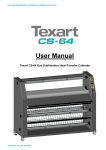
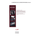
USER’S MANUAL
Mistral 1650_Mistral 2100_Arkane 1650
1
Warranty
Your Mistral, Arkane is guaranteed against all defects of materials and manufacturing for a period of one year
from the date of purchase. In the event of defects of materials or manufacturing, the company which sold the
instrument will repair it or it will be returned to the manufacturer. There is no warranty other than the one
mentioned above. This warranty does not cover individual damage or damage resulting from indirect causes,
whether foreseeable or not. The warranty does not cover incorrect use of the machine.
Return regulations:
If your Mistral, Arkane does not work correctly, first read the instructions again. If the defective operation cannot
be corrected, consult your supplier. Make sure that the series number and the date of purchase of your machine
are to hand, if you have to return the machine to the supplier. Damage during transport resulting from defective
packaging is not covered under the terms of this guarantee.
Declaration of conformity
Kala S.A.S.
Parc de l’Ecotay
35410 Nouvoitou
France
Declares that the following product:
Mistral1650_Mistral2100_Arkane1650 conform to the following requirements
Voltage 230-240V 50-60hz :
• Machines Directive (2009) : 2006/42/CEE including :
• Low tension Directive 2006 95 CE according to the EN 60204 -1 (2006)
• Electromagnetic Compatibility Directive
2004 108 CE According to the EN 61000-6-1 and EN 61000-6-3. Edition 2007.
Always seeking to make progress, we reserve the right to change equipment and technical features or our
models without notice.
2
Summary
1. INSTALLING THE MACHINE
- 1.1 Select the location where the machine should be installed.
- 1.2 Unpacking the machine.
2. CAUTION WHEN INSTALLING THE MACHINE.
- 2.1 Electrical power requirement
- 2.2 Installation
- 2.3 Safety
3. EXPLODED VIEWS AND CONTROL BOARD.
- 3.1 Exploded view of the machine.
- 3.2 Control board.
4. ADJUSTMENTS AND RECOMMANDATIONS
- 4.1 Switching on the machine
- 4.2 Temperature
- 4.3 Roller nip and pressure adjustments
- 4.4 Speed adjustment
- 4.5 Forward and reverse
- 4.6 Memories
- 4.7 Foot switch
- 4.8 Film tension adjustment
p8
p8
p8
p9
p9
p9
p 10
p 10
5. HIGHLIGHTS OF THE MACHINE
- 5.1 Storage of film reels on the machine
- 5.2 Feeding tray
- 5.3 Removable back tray
- 5.4 Unwinding shaft for prints
- 5.5 Safety cutter
- 5.6 Feeding plate
p 11
p 11
p 12
p 12
p 12
p 13
6. FILM INSTALLATION
- 6.1 Loading a reel on a self blocking shaft
- 6.2 Loading a self blocking shaft on the machine
- 6.3 Winding of the film reel
- 6.4 Application and film installation
- 6.5 Roll to Roll operation
- 6.6 Print feeding
p 13
p 13
p 13
p 14
p 20
p 21
7. TECHNICAL DATA
p 22
8. CLEANING, MAINTENANCE AND RECYCLING
p 22
3
1. INSTALLING THE MACHINE:
1.1. Select the location where the machine should be installed
Before unpacking your laminating machine, select the space where the machine should be installed
so that you can easily access all parts of the machine and have enough free space around the
machine.
1.2. Unpacking the machine
Remove the lid on top of the cardboard.
Tear off the cardboard
end and remove it
X4
X4
X1
Unscrew the 4 screws
at each bracket and
remove
the
4
brackets.
Unscrew the wooden
ramp and place it on
the smaller edge of
the pallet.
4
The machine is resting on 2 cardboard blocks (1 at each end). These blocks have to be removed. Lift up the
machine slightly to remove them.
Roll the machine slowly down to the floor on the ramp. For this step, two persons are required to
guide and keep the machine straight.
Finally, place the machine at the required location in your premises.
2. CAUTION WHEN PLUGGING THE MACHINE TO THE POWER
2.1. Electrical power requirement
Before connecting the machine to the power, check that :
-
Your machine’s tension corresponds with the tension of your electrical network.
-
The electrical connection requires a plug compatible with CEI 60309-1.
-
The electrical connection should comply with installation norm NFC 15 100.
2.2. Installation
-
Install the laminator on a flat floor, next to an easily accessible plug.
Do not touch the socket with damp hands.
To unplug the machine, disconnect the plug without pulling on the supply lead.
To prevent electric shocks, do not use this laminating machine close to water.
Leave a large enough working area behind the machine.
Do not spill water on the machine, the supply lead or the electric socket.
Do not use the machine if the supply lead is damaged.
Do not leave the electric lead in contact with a warm surface.
The machine should be installed in a well-ventilated place.
Do not use extension cord with a small diameter section not corresponding to the power of the
machine
Do not plug to a multi-socket plug
2.3. Safety
The laminator has got 3 safety mechanisms that would immediately stop the rotation of the
laminating rollers.
- A laser protection (p) : located on the right side of the machine, next to the roller, it detects
any obstacle (hand or other) that may shut off the laser ray.
!!! CAUTION !!!
Laser ray. Do not watch this
ray directly. Laser product
rated in class 2
-
2 emergency stop buttons : easily reachable, one on the front right hand side and one on
the rear right hand side. The use of one of these emergency stop buttons would switch off
instantly the rotation of the heating drum.
-
The feeding tray (n) : safety is activated when the feeding tray is up and not in the working
position.
5
Safety reset button
Each time one of these safety mechanisms is used, the safety reset key (Rep. 8)
flashes in red. Correct the defect, press on the safety reset key on the control
panel.
Turn the machine off with the main switch (Rep. A) when you have completed your job.
6
3. EXPLODED VIEWS AND CONTROL BOARD
16
14
12
9
6
4
2
3
17
1
15
18
1.
2.
3.
4.
5.
6.
7.
8.
9.
10.
11.
12.
13.
14.
15.
16.
17.
18.
10
11
13
8
7
5
Power key
Foot switch mode selection
Stop
Forward
Reverse
Speed display
Speed adjustment
Reset of the machine safety mechanism
Display of the roller elevation in mm
Adjustment of the roller elevation and pressure
Display of the pressure
Upper roller heat adjustment
Heat selection for the upper roller
Heat ready light
Light indicator for upper roller heating selection
Temperature display
Memorisation of the working modes
Registered working mode selection
d
b
a
c
p
o
c
e
n
m
f
l
a – Main Switch
b – Control board
c – Emergency switches
d – Back tray
e – Upper film reel tension brake handle
f – Rewinding shaft position
g – Lower film reel tension brake handle
h – Castors with brakes
i – Feeding axle for prints
j – Feeding plate
k – Foot switch
l – Self blocking roll shaft
m – Squaring guide
n – Feeding tray
o – Print guide
p – Laser eye
g
k
h
i
j
7
4. ADJUSTMENTS :
-
4.1 Switching on the machine :
Turn on the machine with the main switch (Rep. a) located at the back of the machine.
The control board lights up (light Rep 1). Press « power » (Rep.1).
-
4.2 Temperature adjustment :
To activate the heat of the upper roller, press key
Adjust the upper roller temperature by pressing keys
(Rep.12) on the control board.
(Rep.13).
+
and
-
Temperature adjustment
- Mistral 1650 and 2100 : from 30 to 60° C
- Arkane 1650 : from 40 to 140°C
When light is on, the light (Rep.14) indicates that the set temperature is reached.
Memorisation of the temperature : the last set value replaces automatically the former
value in the selected memory.
-
4.3 Roller nip and pressure adjustments :
Mistral 1650 & 2100 and Arkane 1650 have a nip and roller pressure adjustment.
Opening of the rollers :
The opening is given in millemetres on the display (Rep.9).
Press
(Rep.10) to lift up the roller. Press
(Rep.10) to lower the roller down.
Roller pressure adjustment :
Depending on the work to be done, the pressure can be adjusted from 1 (low pressure =
green light) to 5 (higher pressure = red light).
To increase the pressure, press
(Rep.10) until you until you reach the required
pressure indicated on the pressure measuring gauge (Rep.11) on the control board.
To release the pressure, press
(Rep.10) until you until you reach the required
pressure indicated on the pressure measuring gauge (Rep.11) on the control board.
Recommendation for the pressure adjustment :
Thin paper : Pressure 5
Vinyl, thick paper : Pressure 3/4
Board : Pressure 1
In case waves appears on the print, this can be due to too much or not enough pressure.
In such event, adjust pressure to get rid of the waves.
8
4.4
Speed adjustment :
+
-
Adjust the speed by pressing keys
and
(Rep.7) on the control board until you reached the desired speed,
indicated on the display (Rep.6).
Memorisation of the speed : the last set value replaces automatically the former value in
the selected memory.
While running, the green light will flash faster or lower around the forward key (Rep.4)
depending on the speed setting.
4.5
Forward, stop and reverse
Forward :
Select the speed required first (#4.3). Speed should be minimum set on 1.
Start the machine by pressing the forward key on the control board (Rep. 4).
The machine starts automatically.
For an easy process, it is recommended to start in a slow motion to feed the print
(minimum 1 on the speed display-Rep 6) and increase the speed once sure that it is
feeding correctly into the machine.
Note : when starting in high speed, it is normal to see the machine starting
slowly and increase the speed after one second to reach the set speed.
Stop : to stop the machine, press the Stop key (rep. 3).
Alternatively, you can also stop the machine by pressing on the footswitch if the footswitch
mode is not activated (foot switch light indicator off).
Reverse :
You can go reverse with the machine by keeping your finger pressed on the reverse key
(Rep. 5). If the finger is removed from this key, the machine would stop. When doing this,
the machine would beep, indicating that the rollers are moving backwards. This function is
temporised and would start one second after starting to press. The speed parameter is
fixed at index 3 on the speed display in the reverse mode.
4.6 Memories :
With the memory modes M1, M2, M3 and M4, you can store the speed and temperature
parameters of your most frequent applications.
To select a memory mode :
Select a memory by pressing on the mode selection key (Rep. 18). The memory indicator
1,2,3 or 4 would light when pressing the mode selection key. Stop pressing until you reach
the requested mode.
To change the parameters, adjust speed and temperature. The last set parameters with be
saved when switching to the next mode by pressing the mode key (Rep 18).
9
4.7 Foot switch :
The foot switch mode on the Mistral 1650 & 2100 – Arkane 1650 has got multifunctional
purposes :
a) Working in the foot switch mode :
Start : Press key Rep.2 to select the footswitch mode and the green light next to the key is
lit up. Select the speed to work at and then press on the footswitch to start the rollers.
Both of your hands remain free to guide your print to be laminated or mounted.
While pressing on the foot switch, the laser safety eye is disconnected (all other safety
mechanism are still active). This mode allows to feed documents or material without
shutting off the roller drive because crossing over the laser beam.
When the footswitch is not pressed, the laser safety barrier is activated again.
When using the foot switch mode, the 4 green lights around the forward key will flash
simultaneously, indicating that the laser beam is disconnected.
Switching from foot control to automatic forward :
When the print is fed correctly and running through its lamination process, press the
forward key (Rep. 4) to run automatically.
b) Stop function : If the foot switch mode is not selected (Rep. 2, light off) and the machine
runs automatically, it is possible to stop the machine just by pressing on the foot switch.
c) Running without the foot switch : the foot switch should be connected to the machine to
run correctly. If disconnected from the machine, the machine will still be able to run in
automatic mode. In such a case, to start the machine, press the Footswitch key (Rep. 2)
instead of the forward key (Rep 4)
4.8 Film tension adjustment :
The brake handles (Rep e and g ) enable to adjust the tension of the film reels on the self
lockable shafts.
During lamination, the film should be tight enough for a good lamination result. However, it
is not necessary to give too much tension. Only your tests will enable you to determine the
appropriate film tension. If folds appear on the film on the laminating rollers, increase
slightly the tension on the film reel;
To increase the film tension, turn the handles (Rep. e and g) clockwise.
10
5. HIGHLIGHTS OF THE MACHINE
5.1 Storage of the media reels on the shafts of the machines
There are 4 locations on the machine on which the film reels can be stored on their
blocking shafts.
5.2 Feeding tray :
The feeding tray has got a graduation to enable to centre the prints easily. This graduation
is also related to the one on the self locking shafts.
Pivoting feeding tray : the feeding tray can be lifted up for easy access to the machine
while installing the media or cleaning.
The tray is linked to a safety switch. When in upper position, the driving motor is shut off
and the rollers cannot start. However, it is still possible to lift the roller up and down.
When taken back in working position, press the safety reset key (Rep. 8) on the control
board, and the machine is ready to work.
Squaring guide : A sliding squaring guide is provided with the tray. This guide is lockable
on the table by screwing its button.
It is practical for repetitive jobs with plates.
Paper guide : A removable paper guide is provided to help the insertion of the prints in the
laminator. To position it, slide it in the plastic guides on both ends of the feeding tray.
11
5.3 Removable back tray
The back tray (Rep. d) can be easily removed. It is resting on 2 supports on both sides in
the back of the machine.
Installed, it maintains the board flat after their process.
Removed, the prints can be rewound perfectly and without damages on the laminated roll
take up (Rep.f).
When removed, this tray can be stored in the base front of the machine on the resting
brackets.
5.4 Unwinding shaft for prints
An unwinding shaft (Rep. I) can be used to preserve your print on rolls from dust and
damages. It is meant for small rolls, wounded onto 2” or 3” carton core.
This shaft can be position on the film storage location, or on a free shaft location on the
machine.
5.5 Safety cutter
The rollers are the main part of your laminator. To preserve them and keep the machine
working in its upmost condition, we recommend to avoid cutting with sharp knifes on or
near the roller.
A safety cutter is provided with the machine and enables to cut the material as short as
possible to avoid excess media wastage.
12
5.6 Feeding plate
Use of the feeding plate is described in the media installation section of this manual.
This metal feeding plate is provided to make the installation of the media easier and to
reduce media wastage.
It can be stored in the base front of the machine on the resting brackets.
6. FILM INSTALLATION :
6.1. Loading a film, media or waste paper reel or a carton mandrel onto a self blocking roll shaft :
The 5 locking shafts delivered with the machine can be used on any shaft position on the
machine and in either way.
Loading the media on a shaft is made in 2 steps :
The diameter of the carton mandrel should be 76 mm / 3”.
- Insert the shaft into the carton mandrel of the media, or into the carton on which you
intend to rewind the media.
- Centre it on the shaft using the graduations on the shaft
- To secure a proper locking of the carton mandrel onto the shaft, twist the carton on the
shaft till the locking silicon profile grips the carton mandrel.
1
2
To unload the media roll, twist the mandrel to release it and slide it out.
6.2. Loading a self blocking shaft on the machine
The shaft holder on the right are built with a spring blade that pushes the shaft.
The shaft holder on the left have an index that locks the self blocking shaft index and drives the
shaft.
Before loading the shaft, check the winding way of the media in regards of how it will be fed into the
machine.
Present the shaft where it should be loaded. To make this operation easier, the machine has got
shaft guides on position 2 and 3 on which shaft can rest before being locked in position
Start with the left end side of the shaft then push the right end. Twist the shaft until it gets locked in
the shaft index guide on the left.
6.3 Winding of the film
Depending on your film supplier, the film may be wound inside or outside the roll. When installed,
the glue must face outside the machine, towards the operator.
This winding effects the take up of the film protection paper. Depending on the winding method, the
film and the take up should installed in the following manners.
13
6.4 Application and film installation
The table below showes the position of the media depending on the application
Cold lamination film
application
Position 1
Position 2
Position 3
Single side lamination with
waste paper
Lamination
film
Take up of the Waste
protection liner paper
Position 4
Lamination
Single side lamination
film
directly on a print roll
installed on the machine for
a long run
Take up of the Print roll
protection liner
Single side lamination with
double sided adhesive
simultaneously
Lamination
film
Take up of the Double
protection liner sided
adhesive
Single side lamination with
double sided adhesive
using 2 protection paper
Lamination
film
Take up of the Double
protection liner sided
adhesive
Application tape
Application Application tape should be fed directly to the
tape
roller without going under the separation bar
Lamination of boards,
application of colour vinyl
onto a board
Lamination
film or vinyl
Take up of the
protection liner
Encapsulation (both side
lamination)
Upper
lamination
film
Take up of the Lower
upper film
lamination
protection liner film
Take up of the
double sided
adhesive
protection liner
Take up of the
lower film
protection liner
2
1
4
3
14
Installing the films and use of the feeding plate
6.4 a) Lamination film on the upper position
Lift the roller up and pivot the feeding tray to the top.
Install the film on the centre of a blocking shaft on the position 1 of the machine.
The sticky side of the film should be facing outside the machine towards the user. Refer to the
winding way of the film roll to confirm the way the paper should go.
Install a shaft with a carton mandrel on position 2 to take up the protection paper of the film.
Separate the film from its protection paper after the separation bar.
Stick the protection paper on the carton mandrel with adhesive tape.
Tear on the film and position it on the lamination roller
.
15
6.4 b) Lamination with waste paper, double side adhesive, or direct lamination of a print roll.
Install the upper film as described above.
Install the waste paper, double side adhesive, or print roll on a blocking shaft on position 3 and
centre it with the graduation..
Align this media in regards with the lamination film. Help yourself with the graduations on the
shafts. Double side adhesive should go directly to the lamination film bypassing the separation bar.
Once aligned, stick this media onto the lamination film
Lock the self blocking shaft on the lower position with the locker on the right of the machine.
Take the feeding tray down in working position. Place the feeding plate between the lamination
roller.
16
Take the roller down in contact with the feeding plate without pressure.
Press on the safety reset key and start the machine by pressing the forward key.
The plate goes through the roller and both media are stick together.
The film is well aligned with the waste paper, double side adhesive or print.
Once installed , adjust the tension on the upper film and lower media with the film brakes to get rid
of eventual folds.
6.4 c)
Application tape
Lift the roller up and pivot the feeding tray to the top.
Install the application tape on the centre of a blocking shaft on the position 1 of the machine.
The sticky side of the film should be facing outside the machine towards the user.
The application tape should go directly to the roller bypassing the separation bar.
Tear on the application tape at the back of the machine to give a even tension.
To avoid the application tape sticking to the roller, you may use the feeding plate or a waste paper
before you insert your vinyl.
Lower the lamination roller down and start the machine with your cut vinyl.
6.4 d)
Double side lamination / encapsulation
Install a film on the upper position 1
Install another lamination film roll on position 3 and centre it with the graduation..
Align this film with the upper lamination film. Help yourself with the graduations on the shafts.
The sticky side of the film should be facing outside the machine towards the user. Refer to the
winding way of the film roll to confirm the way the paper should go.
Install a shaft with a carton mandrel on position 4 to take up the protection paper of the lower film.
Separate the film from its protection paper after the separation bar.
Stick the protection paper on the carton mandrel with adhesive tape.
Tear on the film and position it on the upper lamination film.
Once aligned, stick this media onto the lamination film
Lock the self blocking shaft on the lower position with the locker on the right of the machine.
Take the feeding tray down in working position. Place the feeding plate between the lamination
roller.
Take the roller down in contact with the feeding plate without pressure.
Press on the safety reset key and start the machine by pressing the forward key.
The plate goes through the roller and both films are stick together.
17
Once installed , adjust the tension on both film with the film brakes to get rid of eventual folds on the
film.
6.4 e)
Mounting onto rigid boards
Remove the film on the machine. Install the back tray back on the machine to guide the board when
going out of the rollers.
Lift up the roller to the required thickness. A first test with the board and no print will enable to
determine the right elevation. For this operation, it is recommended to work with low pressure (1or
2)
Remove the protection paper of the adhesive back on a stripe of 5 cm and fold it.
Stick manually this stripe on the board.
Insert the board, adhesive first, between the rollers.
Flip the print to the back of the machine and keep the print on the top roller so that this one keep the
roller shape and avoid folds.
Adjust the speed and press the forward key or the foot switch. While the board is fed through the
machine, remove the protection paper manually, tearing it to the back.
Note : For easier operation with the machine for mounting onto
boards, we recommend to use the foot switch, specially when
finishing the mounting. By doing this, the laser barrier is shut
off and the paper flipping over at the end of the vinyl won’t stop
the machine.
6.4 f)
Lamination of rigid boards or direct application of color vinyl onto a board
Install film or colour vinyl as described in 6.4 a)
Lift up the roller to the required thickness
Tear on the film or vinyl at the back of the machine.
Insert the board between the roller.
Start the rollers by pressing the forward key on the control board or the foot switch if selected.
18
6.5 Roll to roll operation
To work without dust and for easy handling of the laminated prints.
Loading the print roll.
Smaller print roll can be loaded on the print holder shaft delivered with the machine.
This can be loaded
on one of the film storage position
Or on a self blocking shaft on position 4.
Long print roll, rewound on a 3” core mandrel, can be loaded as a waste paper (cf 6.4 b), taking it
under the separation bar.
Loading the rewinding system
• Install a shaft with a carton mandrel on the rewinding position.
Remove the back tray.
19
•
Let the lamination go out of the machine to the rewinding shaft.
Tear on the laminated print and stick it onto the carton mandrel.
•
The rest of the laminated print roll will be rewound in accordance with the selected speed.
The rewinding speed is linked to the lamination speed and the laminated prints will be
wound automatically on the mandrel.
Unloading the rewinding system
When the lamination is finished, stop the machine by pressing on the foot switch or the stop key on
the control board.
Cut the laminated print roll with the safety cutter and remove the shaft.
20
6.6 Print feeding
Select pressure and starting speed. Select footswitch on the control panel (Rep. ) if needed.
Feed the print maintaining it straight and tight at each corner.
For easier process to keep the print flat, slide it under the paper guide in front of the roller.
Press forward on the control panel or on the foot switch to start.
Maintain the print until it is fed through the rollers.
Let run through the machine.
Press stop on the control panel or on the foot switch when finished.
21
7. TECHNICAL DATAS :
Maximum working width (in mm)
Maximum thickness between the rollers
(in mm)
Strength on the rollers (in daN)
Maximum speed (in m/min)
Dimensions W x H x D (in cm)
Weight (in kg)
Temperature of the upper heating roller
(in C°)
Heating power (in watt)
Voltage
Ampers (A)
Mistral 1650
1650
50
Mistral 2100 Arkane 1650
2100
1650
50
50
30 to 100
6
206x153x82
210
30 to 60
30 to 100
6
280x153x82
257
30 to 60
30 to 100
6
206x153x82
210
40 to 140
1700
230-240V
50-60Hz
8.5
1700
230-240V
50-60Hz
8.5
1700
230-240V
50-60Hz
8.5
This machine has been designed and built so that the noise caused by functioning is lower than 70
dB.
8. CLEANING, MAINTENANCE, RECYCLING :
8.1 Cleaning :
When
Immediately
Weekly
What
Ink on the rollers
Laminating rollers *
Feeding tray
Back tray
Upper & lower tension bars
Action
soap and water
soap and water
soap and water
soap and water
soap and water
(*) : Cleaning the rollers should be done when the machine is switched off, the roller and the feeding
tray are lifted up.
8.2 Maintenance :
User maintenance is limited to the action listed in 7.1. For other question or inquiry, contact
your distributor.
8.3 Recycling :
Laminators Mistral and Arkane have got no components that are not environment friendly.
Recycling must be made by an authorised recycling company
22