1
CPU_45A-V3
CPU Board XMC4500 General Purpose
Hardware Description
2.5.2
Cortex Debug Connector (10-pin)
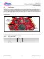
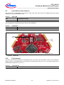
The CPU_45A-V3 board supports Serial Wire debug operation and Serial Wire viewer operation (via the SWO
signal when Serial Wire debug mode is used) through the 10-pin Cortex Debug Connector.
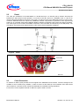
When using an external debugger connected to the 10-pin Cortex Debug Connector, the on-board debugger is
switched off.
Cortex Debug
Connector (10-pin)
VCC
1
2
SWDIO / TMS
GND
3
4
SWDCLK / TCK
GND
5
6
SWO / TDO
KEY
7
8
NC / TDI
GNDDetect
9
10 nRESET
cortex-10pin.emf
Figure 11 Cortex Debug Connector (10-pin)
Table 4
Cortex Debug Connector (10 Pin)
Pin No.
Signal Name
Serial Wire Debug
JTAG Debug
1
VCC
+3.3 V
+3.3 V
2
SWDIO / TMS
Serial Wire Data I/O
Test Mode Select
3
GND
Ground
Ground
4
SWDCLK / TCK
Serial Wire Clock
Test Clock
5
GND
Ground
Ground
6
SWO / TDO
Trace Data OUT
Test Data OUT
7
KEY
KEY
KEY
8
NC / TDI
Not connected
Test Data IN
9
GNDDetect
Ground Detect
Ground Detect
10
nRESET
Reset (Active Low)
Reset (Active Low)
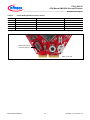
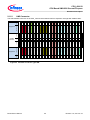
Cortex Debug
Connector (10 Pin)
10Pin_Conn.emf
Figure 12 Cortex Debug Connector (10-pin) Layout
Board User's Manual
15
Revision 1.0, 2014-01-10