1
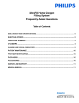
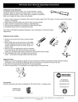
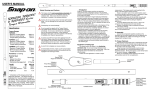
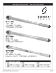
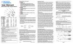
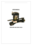
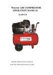
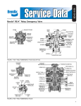
User Manual
Features and Benefits
Extremely Accurate Accurate within 2% of reading from 20% of
full scale to full scale. Guaranteed against defect in workmanship and
materials for one year from the date of delivery providing that they
have been used according to instructions.
Exclusive Torsion Bar Design This patented design features a
connecting arm directly from the square drive to the easy-to-read dial.
This enables the user to read the actual twist of the square drive. And,
since a lever principle isn't used, hand-hold position is not critical,
unlike the split or bending beam competitive torque wrenches.
Compact Design and Tapered Nose This provides ease-ofoperation by allowing clearance where operating space is limited.
Large Shock Resistant Dials Protected by dial "guards", the large
easy-to-read dial numbers are set off against a contrasting color. With
many increments on the scale, guess work is eliminated.
Dial Pointers Work in either right or left-hand direction. The dial
can also be rotated so the user can torque to zero from the desired
value.
Memory Needle Models Retain the highest torque reading for easy
reference. For Quality Control testing, a Memory Needle Model
displays the maximum reading obtained. This is excellent for verifying
production torque applications.
Indicator Light Models Indicates when a preset torque level is
achieved. Set the dial to the required torque, and the light will go on
when the proper torque is reached. This is particularly useful when the
dial is not visible.
Shock-Resistant Dial Mechanism Built to withstand rough usage,
the mechanism which provides the expanded dial readings is shock
protected with resilient and overload members.
Consistent Readings The accuracy is not affected by the way it is
held. Pull on the end of the handle or close to the dial and the reading
remains the same. Handle extensions are furnished with many models
which allow even greater flexibility.
Compact The square drive is located at the very end of the torque
wrench so that it can be used in areas where space is at a minimum.
Friction-Free Operation A floating connecting beam between the
torque measuring element and the dial mechanism has no bearing
points and consequently there is no friction drag. This floating beam
construction together with the precision of the dial mechanism renders
the torque wrench practically friction-free.
Accurate and Dependable All Precision Instrument D Torque
wrench Series meets or exceeds all applicable requirements of:
ANSI / ASME B107.14M, GGG-W-00686C, BS6073: 1988, ISO6789.
TO GET ACCURATE TORQUE READINGS
Your torque wrench is a precision instrument. Given proper care it will give
many years of satisfactory use. For best results and accurate readings follow
the instructions given below.
1. Set the dial of the Torque wrench by using method “A” or “B” explained
below. Method A: 1) Turn the dial until the pointer is on zero. 2) Place the
Torque wrench on the fastener. 3) Pull until the pointer reaches the torque
required. Method B: 1) Turn the dial until the pointer is at the torque
required. (On right hand threads set to the left of zero. On left hand threads
set to the right of zero.) 2) Place the Torque wrench on the fastener. 3) Pull
until the pointer reaches zero.
2. To make it easier to read the dial of all except the Memory Needle
models, it is possible to place the pointer in any desired position. Turn the
dial until the pin bears against the pointer. Then turn the dial 1/4 turn past
the position desired. Finally, turn the dial in the other direction. The pointer
will follow the pin back until it reaches the position desired. Then proceed
with either Method “A” or “B,” as explained above.
3. To use the Indicator Light Model for clockwise applications, turn the
dial until the gold pointer is set at the desired torque (the red pointer for
counterclockwise applications). Place the Torque wrench on the fastener
and pull until the light comes on. Check the bulb and battery if the light
fails to light when the pointer touches the gold contact pin.
4. To use the Memory Needle Model in the clockwise direction, rotate
knurled knob counter clockwise on top of crystal until Memory Needle
contacts main pointer. Next turn the dial bezel counter clockwise until the
Memory Needle is on zero. Place the Torque wrench on the fastener and
pull on the wrench handle until the desired torque is reached. When the
pressure is released the main pointer will return to zero and the Memory
Needle will remain at the peak torque reached. For counter clockwise
direction use, reverse above procedure.
The Memory Needle feature can be used to record peak torque when the
Torque wrench dial may not be visible. Be careful not to overtorque the
fastener or Torque wrench.
5. Each time the Torque wrench is used, be sure that the dial and pointer
are set correctly.
6. After each use of the Torque wrench make sure the pointer returns to
zero or the pre-set value. If not, re-set the dial and pull again.
7. For an accurate reading, the final turn of the nut should be made with the
Torque wrench.
8. The hub of the pointer contains a clutch which allows the stem to turn
within the hub if a sudden impact occurs. This important safety factor
protects the dial mechanism from shock damage. If a fastener suddenly
breaks, it may change the pointer setting. Reset the dial and proceed as
before.
9. Work on fasteners with clean and lubricated threads.
10. Your Torque wrench does not need lubrication. Do not attempt to oil it.
TORQUE PRODUCTS FULL WARRANTY
PRECISION INSTRUMENTS WARRANTS THAT PRECISION TORQUE
PRODUCTS ARE FREE FROM DEFECTS IN WORKMANSHIP AND
MATERIALS. Precision Instruments will repair or replace these tools which fail
to give satisfactory service due to defective workmanship or materials.
This warranty for Precision Instruments torque products is for ONE YEAR from
the date of the original purchase. Repair or replacement shall be at the
election and expense of Precision Instruments . Except where unreasonable,
the product must be returned to Precision Instruments prepaid for warranty
service. Precision Instruments does not provide any warranty for any product,
or its calibration, subjected to abnormal use. Abnormal use includes misuse,
modification, unreasonable use, neglect, lack of maintenance, lack of periodic
calibration, or use after the tool is significantly worn.
PRECISION INSTRUMENTS SHALL NOT BE LIABLE FOR ANY
INCIDENTAL, SPECIAL OR CONSEQUENTIAL COSTS OR DAMAGES
INCURRED BY THE PURCHASER OR OTHER including, without limitations,
lost profits, revenues, anticipated sales, business opportunities, goodwill, or
interruption of business and any other injury of damage. Some states do not
allow the exclusion or limitation of incidental or consequential damages, so the
above limitation or exclusion may not apply to you. This warranty is your
exclusive remedy and is in place of all other rights and remedies. You may
have other rights which vary from state to state or country.
Precision Instruments, Inc.
Warranty Information
P. O. Box 1306
Des Plaines, IL 60017
Rev 01/03
IN1202-PI
Printed in U.S.A.
Why Measure Torque
Modern consumer demand has forced industry to upgrade
manufacturing efficiency. Because of this, manufacturers have
expanded their production through special emphasis on such specifics
as ‘‘increased power per cubic inch,’’ ‘‘power per dollar’’ and
‘‘product efficiency factor per pound.’’ In researching the need for
increased product efficiency and the importance of complying with
stringent safety standards, manufacturers found that the ‘‘nuts and
bolts’’ principle needed special attention. Older products and machines
were assembled using oversized parts having high safety factors and
enormous strength. These assemblies required minimal attention, since
nuts and bolts were much larger than necessary. In order to increase
product efficiency per pound, smaller, more efficient machinery had to
be produced using smaller yet stronger fasteners. Because of this, the
‘‘nuts and bolts’’ principles have new importance.
Threaded Fasteners
Threaded fasteners are used on all types of machinery, yet proper
attention is often neglected. Improper torque can cause enough
distortion to fracture castings, accelerate wear or cause running parts to
seize. It is a known fact that a simple half-inch bolt may exert a force as
high as 16,000 pounds-enough force to lift four or five automobiles.
Quite obviously, threaded fasteners require special attention. Because
of the importance nuts and bolts play in product efficiency, the Society
of Automotive Engineers has established standards of minimum tensile
strength for all major classes of threaded fasteners used by industry.
Actually, the minimum tensile strength is only potential, considering
practical usage. Because fasteners are used to hold assembly
components together, stress caused by rapidly changing loads often
complicates the fastener’s job. For example, under stress the
investment in extra potential strength of an SAE grade five bolt is lost,
and the quality of the entire machine lessened, if it is not properly
tightened. Bolts not tightened properly may eventually loosen and fall
out. Even bolts secured with a locking devise, may fail from fatigue.
When a bolt is properly tightened, extra locking devices are
unnecessary. For its cost, the heat treated SAE grade five bolt offers the
greatest potential strength in standard production situations. But, to
realize this potential, the bolt must be properly tightened.
A Few Standard Precautions
A few standard precautions will solve fastener problems. Since the
fastener is usually the weakest link in any assembly, special attention is
always necessary. This means that an incorrectly tightened fastener will
fail before the machine itself fails. The job of determining proper bolt
tightening. is simple. First, examine the bolt itself to determine its
torque limits. Then check its maximum potential. Naturally, there are
circumstances which will determine procedures and torque value for
special situations but these are rare. Caution! Always consult
manufacturers specifications when available. The most commonly used
rule for determining proper torque for a fastener is to apply 70% of the
torque necessary to cause failure. The ‘‘Production Torque Guide’’
chart in this manual indicates these values. Tightening to utilize the
fastener’s potential strength is a necessary part of the fastener story, but
it isn’t the whole story. Proper lubrication, washers, etc. are just as
important as proper tightening, since as much as 80% of the torque
applied to a fastener is lost through friction. When the relationship
between torque and tension is out of control, reliability is out; therefore,
proper lubrication is necessary to provide a constant clamping force
over a series of applications.
The best lubrication is a high stress type, such as ‘‘Never-Seez’’
Compound. On non-critical applications, seventy-two hour zinc
phosphate and oil coating may be used. This is an inexpensive coating
From
lb.in.
lb.in.
lb.in.
lb.in.
lb.in.
lb.in.
lb.ft.
lb.ft.
N•m
N•m
N•m
CONVERSION OF VARIOUS UNITS OF TORQUE
Convert
Convert
To
Multiply
From
To
Multiply
oz.in.
16
oz.in.
lb.in.
.0625
lb.ft.
.08333
lb.ft.
lb.in.
12
kg.cm.
1.1519
kg.cm.
lb.in.
.8681
kg.m.
.011519
kg.m.
lb.in.
86.81
N•m
.133
N•m
lb.in.
8.85
dN•m
1.13
dN•m
lb.in.
.885
kg.m.
.1382
kg.m.
lb.ft.
7.236
N•m
1.356
N•m
lb.ft.
.7376
dN•m
10
dN•m
N•m
.10
kg.cm.
10.2
kg.cm.
N•m
.09807
kg.m.
.102
kg.m.
N•m
9.807
and is furnished on many industrial fasteners direct from the
manufacturer.
Also, the surface under the head of the bolt or under the nut
(whichever is the turned member) is important. Many manufacturers
use hard flat washers with no spring effect. The hardness contributes
to good correlation between the torque applied and the tension
achieved. The unbroken circular flatness contributes to dimensional
control and consistency of clamping force from bolt to bolt. Locking
devices offer some protection against improper tightening. One of
the latest trends is the use of nuts with physical disrupted threads to
insure fastener locking. This type of device is manufactured by
several companies, but should be examined for it’s own merits.
(Remember, however, that galling can disrupt the torque-tension
correlation when locking devices are used.)
HOW TO COMPUTE TORQUE WHEN USlNG ADAPTORS
If an adaptor or extension is attached to the square drive of a click-type
torque wrench and this adds to its length, then the applied torque will
be greater than the pre-set torque. A formula can be used to find what
the preset-set torque should be in order to obtain the correct applied
torque.
Here is the formula:
Dial Reading . Torque Wrench Pull Point x Torque Desired
or
=
Pre-Set Torque . Torque Wrench Pull Point + Extension Length
This becomes: RS =
AxT
when
A+B
RS = Dial reading or torque setting of the wrench.
A = Distance from the center of the square drive of the torque wrench to
the center of the handle grip pull point.
B = Length of the adaptor from the center of the square drive to the
center of the nut or bolt. Use only the length which is parallel to the
handle. See figure 1
T = Torque desired. This is the actual torque applied to the fastener.
Here is a typical problem: What should the setting be when ‘‘A’’ is
12’’, ‘‘B’’ is 6’’ and ‘‘T’’ is 30 Ib. ft.
RS =
AxT
or
A+B
12 x 30
12 + 6
or
360
or 20 pound foot
18
Therefore 30 pound foot of Torque will be applied at the fastener when
‘‘RS’’ is 20 pound foot.
Note: If the torque wrench reads in pound foot, then ‘‘T’’ should also
be in pound foot. ‘‘T’’ and ‘‘RS’’ should be in the same unit of
measurement. ‘‘A’’ and ‘‘B’’ should also be the same unit of
measurement.
B
A
NO
B
A
NO
B
A
Figure 1 – Formula values for a Torque wrench
THREADED FASTENER TENSION GUIDE
( Figures Represent Pounds of Clamping Force )
GENERAL TORQUE SPECIFICATION CHART FOR I.S.O.** METERIC FASTENERS*** ( when SAE 10 oil is used as a lubricant )
Minimum
40
50
60
80
100
120
Tensile
kg/mm2
Strength
P.S.I.
56900
71100
85340
113800 142200 170700
Proof
kg/mm2
22.6
29.1
28.2
36.4
33.9
43.7
47.5
58.2
79.2
95
Load
P.S.I.
32150
41390
40110
51770
48220
62160
67560
82780
112650 135130
Property Class
4.6
4.8
5.6
5.8
6.6
6.8
6.9
8.8
10.9
Stress Area
0.0091
Outside Diameter
No.6
Threads Per Inch
32
Torque:
5 lb.in. 205
10 lb.in. 410
20 lb.in. 820
40 lb.in.
80 lb.in.
12.9
Figures are KILOGRAM METER except those that are bolded which are KILOGRAM CENTENETER
Bolt Diameter
Metric
Inch
6 mm
0.236
49
63
61
79
74
95
103
126
172
206
119
153
148
191
178
230
250
306
417
500
8 mm
0.315
10 mm
0.394
235
303
294
379
353
455
495
606
8.2
10
12 mm
0.472
411
529
427
662
616
7.9
8.6
10.5
14
17
14 mm
0.551
654
8.4
8.2
10.5
10
12
13
17
23
27
16 mm
0.63
10
13
12
16
15
20
21
26
36
43
18 mm
0.709
14
18
17
23
21
27
30
36
49
59
22 mm
0.866
27
35
34
44
41
52
57
70
95
114
*** NOTE: Use only when manufacturers specifications are not available, these values are for stiff metal-to-metal joints and are based on
90% of proof load. DO NOT USE for gasket joints or joints of soft materials
** I.S.O.= International Standardization Organization.
If Your Torque Wrench Needs Repair
1. Send it to an authorized Precision Instruments Service Center, or
give it to your Precision Sales representative. Do not attempt to repair it
yourself.
2. If the warranty is no longer in effect, your Precision Instruments
Customer Service Representative will contact you with repair charges
for your approval before being repaired.
3. A series of testers are available from Precision Sales for checking
the accuracy of your Torque Wrench. See your Precision Sales
representative for more information.
0.0524
5/16"
18
337
674
1348
541
1082
2043
4092
1625
3250
6503
0.0775
3/8"
16
0.1063
7/16"
14
0.1419
1/2"
13
0.1819
9/16"
12
0.226
5/8"
11
0.3344
3/4"
10
0.4617
7/8"
9
1224
2448
4896
9796
2143
4286
8572
3899
7799
7065
9749
12186
14623
17061
19498
24373
0.6057
1"
8
0.7632
1-1/8"
7
0.9691
1-1/4"
7
8832
11049
13261
15462
7915
9894
11872
13851
12117
17664
22100
26523
15830
19788
23745
31660
39576
12245
10716
13395
16091
500 lb.ft.
750 lb.ft.
1,000 lb.ft.
1,500 lb.ft.
13836
17296
20776
27700
12113
15142
18170
24227
11985
14382
19176
13247
17663
34592
51941
30284
45426
60569
23971
35956
47942
71985
2,000 lb.ft.
3,000 lb.ft.
5,000 lb.ft.
10,000 lb.ft.
20,000 lb.ft.
Visit us at: www.torqwrench.com
1.4052
1-1/2"
6
1.8993
1-3/4"
5
2.8917
2"
12
4.5951
2-1/2"
12
22079
33118
44158
66237
19754
29631
39508
59262
22678
30238
45358
31724
47587
36289
88317
79017
118525
197543
60477
90716
151193
302387
63449
95174
158624
317248
987
1482
2964
5928
11857
200 lb.ft.
250 lb.ft.
300 lb.ft.
400 lb.ft.
In some cases it may be desirable to know the total clamping force obtained for a given torque. Values are approximate. SAE 30 engine oil
was used as lubricant. Use of high stress lube may increase value 20% or more. Highest values for a given size may only be obtained with
heat treated bolts having minimum tensile strengths of 150,000 P.S.I. or more.
Caution
GENERAL TORQUE SPECIFICATION CHART
FOR I.F.I.* METRIC FASTENERS**
( when SAE10 oil is used as a lubricant )
Minimum Tensile ***
400
420
520
830
900
1040
1220
Strength Mpa
Proff Load MPa
225
310
380
600
650
830
970
Property Class
4.6
4.8
5.8
8.8
9.8
10.9
12.9
Bolt Diameter
Torque: Newton Metre
metric
inch
5mm
0.197
2.9
4
5
8
11
12
6mm
0.236
5
7
8
14
18
21
7mm
0.276
8
11
14
24
30
35
8mm
0.315
12
16
20
34
44
50
10mm
0.394
23
32
40
70
85
100
12mm
0.472
40
56
70
120
150
180
14mm
0.551
65
90
110
190
240
280
16mm
0.63
100
140
170
270
290
380
440
20mm
0.787
200
330
520
740
860
24mm
0.945
340
580
920
1260
1480
30mm
1.181
680
1820
2520
2940
*** Megapascal
** Note: Use only when manufacturers specifications are not available, these values are
for stiff metal-to-metal joints and are based on 90% of proof load. DO NOT USE for
gaskets joints or joints of soft materials.
* I.F.I. = Industrial fasteners Institute.
315
630
1264
0.0318
1/4"
20
100 lb.ft.
125 lb.ft.
150 lb.ft.
175 lb.ft.
E-mail us at: [email protected]
Fastener
0.0175
No.10
24
10 lb.ft.
20 lb.ft.
40 lb.ft.
80 lb.ft.
Precision Instruments, Inc. Sales (toll free): 866-TWRENCH
1846 Miner Street
(866-897-3624)
P.O. Box 1367
Des Plaines, IL. 60017
Fax: 847-824-7629
Always use manufacturers specifications when available. These
specifications are approximate and may not be appropriate for some
applications. No liability is assumed for errors which may result
from the use of any of these specifications.
0.0141
No.8
32
157
316
632
1264
48386
72579
120966
241932
483864
* Stress area is calculated as the area of the circle whose diameter is the mean between the root and pitch diameters. This
closely approximates the actual stress condition. Maximum theoretical clamping force cannot be obtained from threaded
fasteners. Additional stresses to the fastener are caused by the torsional forces of tightening.
PRODUCTION TORQUE GUIDE
Body size of Outside Diameter
1/4 5/16 3/8 7/16 1/2 9/16 5/8 3/4 7/8 1 1-1/8 1-1/4 1-3/8 1-1/2 1-5/8 1-3/4 1-7/8
Type
Minimum
Tensile
Strength
Material
S.A.E 2 Steel
74000 P.S.I
Low Carbon
6
12
20
32
47
S.A.E. 5 Steel
120000 P.S.I
Medium Carbon Heat
Treat
10
19
33
54
78 114 154 257 382 587 794
S.A.E. 7 Steel
133000 P.S.I.
Medium Carbon Alloy
13
25
44
71 110 154 215 360 570 840 1325 1825 2500 3000 4000 5300 7000 7500 11000 15500 21000 27000
S.A.E. 8 Steel
150000 P.S.I.
Medium Carbon Alloy
14
29
47
78 119 169 230 380 600 900 1430 1975 2650 3200 4400 5650 7600 8200 12000 17000 23000 29000
16
33
54
84 125 180 250 400 640 970 1520 2130 2850 3450 4700 6100 8200 8800 13000 18000 24000 31000
Socket Head
Cap Screw
Socket Set
Screw
Machine Screw
Stainless
Machine Screw
Stainless
Machine Screw
Yellow Brass
Silicone Bronze
Type "B"
Machine Screw
Aluminum
Machine Screw
Monel
Sems Heat
Treated Steel
Studs
Tapping Screw
160000 P.S.I.
212000 P.S.I.
60000 P.S.I.
2
3
4
5
High Carbon Quenched
Tempered
High Carbon Quenched
Tempered
6
9*
8
10
69
96 155 206 310 480
16* 30* 70* 140* 18
29
43
63 100 146
675
900
2.6* 4* 5.5* 8*
10* 20* 23* 75* 132* 20
31
43
58
95 130 194 260 400
500
725
316
2.7* 4* 5.7* 8*
10* 22* 25* 80* 140* 22
34
46
60 100 135 210 280 425
515
750
16* 20* 65* 110* 17
27
37
49
78 104 160 215 325
400
595
2* 3.3* 4.4* 6.4* 8*
70000 P.S.I.
CU 96 ZNI-5 Min.
2.3* 3.7* 4.9* 7.2* 10* 19* 22* 70* 125* 20
30
41
53
88 117 180 250 365
450
655
55000 P.S.I.
CU 3.8-4.9 1.2-1.8
MN .3-.9
1.4* 2.1* 2.9* 4.3* 5.4* 12* 15* 46* 82*
13
20
27
36
62
83 128 170 255
315
460
11* 21* 27* 87* 155* 23
36
50
67 115 155 235 315 475
585
850
82000 P.S.I.
120000 P.S.I.
NI 67 CU 30 FE 1.4 2.5* 4* 5.5* 8*
1018 1022
4*
5*
7*
2-1/4 2-1/2 2-3/4
3
9500
1105 1500 1775 2425 3150 4200 4550 6550 7175 13000 16000
18-8
CU 63 ZN 37
2
1100 1470 1900 2360 2750 3450 4400 7350
11* 15* 27* 37* 90* 200* 330*
Use SAE 2.5 and 8 values when grade is known, with nut of sufficient strength.
Set up joint as it will be in production use 70% of over-torque failure as production specifications.
All figures are POUND FEET except those marked with an ASTERISK ( * ) WHICH ARE pound inches. These
values are for lubricated fasteners.
Zeroing the
Precision Instruments
D-Line Dial-Type Torque
Wrench
Zeroing the
Precision Instruments
D-Line Dial-Type Torque
Wrench
Zeroing the
Precision Instruments
D-Line Dial-Type Torque
Wrench
Zeroing the
Precision Instruments
D-Line Dial-Type Torque
Wrench
The wrench is shipped with the
main pointer lined up on the zero
mark and pointing straight forward.
The wrench is shipped with the
main pointer lined up on the zero
mark and pointing straight forward.
The wrench is shipped with the
main pointer lined up on the zero
mark and pointing straight forward.
The wrench is shipped with the
main pointer lined up on the zero
mark and pointing straight forward.
If the main pointer ever comes to
rest at an angle other than straight
forward, hold the outer dial ring
with your index finer and thumb…
If the main pointer ever comes to
rest at an angle other than straight
forward, hold the outer dial ring
with your index finer and thumb…
If the main pointer ever comes to
rest at an angle other than straight
forward, hold the outer dial ring
with your index finer and thumb…
If the main pointer ever comes to
rest at an angle other than straight
forward, hold the outer dial ring
with your index finer and thumb…
And turn the outer dial ring to line
up the main pointer with the zero
mark. Note: This will not affect the
calibration of the tool.
And turn the outer dial ring to line
up the main pointer with the zero
mark. Note: This will not affect the
calibration of the tool.
And turn the outer dial ring to line
up the main pointer with the zero
mark. Note: This will not affect the
calibration of the tool.
And turn the outer dial ring to line
up the main pointer with the zero
mark. Note: This will not affect the
calibration of the tool.
IN1247 10/07
IN1247 10/07
IN1247 10/07
IN1247 10/07