1
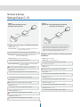
MEGApix® Panoramic
2.1MP 180° Camera
DWC-PV2M4T
User’s Manual
Ver. 1.0 / 2015.04.21
Before installing and using the camera, please read this manual carefully.
Be sure to keep it handy for future reference.
Safety Information
CAUTION
RISK OF ELECTRIC SHOCK.
DO NOT OPEN.
CAUTION:
TO REDUCE THE RISK OF ELECTRIC SHOCK, DO NOT REMOVE COVER (OR BACK) NO USER SERVICEABLE
PARTS INSIDE. REFER SERVICING TO QUALIFIED SERVICE PERSONNEL.
Warning
Precaution
This symbol indicates that dangerous voltage
consisting a risk of electric shock is present within
this unit.
This exclamation point symbol is intended to alert the
user to the presence of important operating and
maintenance (servicing) instructions in the literature
accompanying the appliance.
WARNING
Precaution
To prevent damage which may result in fire or electric shock
hazard, do not expose this appliance to rain or moisture.
Operating
• Before using, make sure power supply and all other parts are
properly connected.
• While operating, if any abnormal condition or malfunction
is observed, stop using the camera immediately and contact
your dealer.
WARNING
1. Be sure to use only the standard adapter that is specified in
the specification sheet. Using any other adapter could cause
fire, electrical shock, or damage to the product.
Handling
• Do not disassemble or tamper with parts inside the camera.
• Do not drop the camera or subject it to shock or vibration as
this can damage the camera.
• Clean the clear dome cover with extra care. Scratches and
dust can ruin the quality of the camera image.
2. Incorrectly connecting the power supply or replacing battery
may cause explosion, fire, electric shock, or damage to the
product.
3. Do not connect multiple cameras to a single adapter.
Exceeding the capacity may cause excessive heat generation
or fire.
Installation and Storage
• Do not install the camera in areas of extreme temperature,
exceeding the allowed range.
• Avoid installing in humid or dusty environments.
• Avoid installing in places where radiation is present.
• Avoid installing in places where there are strong magnetic
fields and electric signals.
• Avoid installing in places where the camera would be subject
to strong vibrations.
• Never expose the camera to rain or water.
4. Securely plug the power cord into the power receptacle.
Insecure connection may cause fire.
5. When installing the camera, fasten it securely and firmly.
A falling camera may cause personal injury.
6. Do not place conductive objects (e.g. screw drivers, coins,
metal items, etc.) or containers filled with water on top of
the camera. Doing so may cause personal injury due to fire,
electric shock, or falling objects.
7. Do not install the unit in humid, dusty, or sooty locations.
Doing so may cause fire or electric shock.
8. If any unusual smells or smoke come from the unit, stop
using the product. Immediately disconnect the power
source and contact the service center. Continued use in
such a condition may cause fire or electric shock.
9. If this product fails to operate normally, contact the nearest
service center. Never disassemble or modify this product in
any way.
10. When cleaning, do not spray water directly onto parts of the
product. Doing so may cause fire or electric shock.
1
Important Safety Instructions
1. Read these instructions. - All these safety and operating instructions should be read before the product is
installed or operated.
2. Keep these instructions. - The safety, operating and use instructions should be retained for future reference.
3. Heed all warnings. - All warnings on the product and in the operating instructions should be adhered to.
4. Follow all instructions. - All operating and use instructions should be followed.
5. Do not use this device near water. - For example: near a bath tub, wash bowl, kitchen sink, laundry tub, in a wet
basement; near a swimming pool; etc.
6. Clean only with dry cloth. - Unplug this product from the wall outlet before cleaning. Do not use liquid cleaners.
7. Do not block any ventilation openings. Install in accordance with the manufacturer’s instructions. - Slots and
openings in the cabinet are provided for ventilation, to ensure reliable operation of the product, and to protect it
from over-heating. The openings should never be blocked by placing the product on bed, sofa, rug or other similar
surface. This product should not be placed in a built-in installation such as a bookcase or rack unless proper
ventilation is provided and the manufacturer’s instructions have been adhered to.
8. Do not install near any heat sources such as radiators, heat registers, or other apparatus (including amplifiers)
that produce heat.
9. Do not defeat the safety purpose of the polarized or grounding-type plug. A polarized plug has two blades with
one wider than the other. A grounding type plug has two blades and a third grounding prong. The wide blade
or the third prong are provided for your safety. If the provided plug does not fit into your outlet, consult an
electrician for replacement of the obsolete outlet.
10. Protect the power cord from being walked on or pinched particularly at plugs, convenience receptacles, and
the point where they exit from the apparatus.
11. Only use attachments/accessories specified by the manufacturer.
12. Use only with cart, stand, tripod, bracket, or table specified by the
manufacturer, or sold with the apparatus. When a cart is used, use
caution when moving the cart/apparatus combination to avoid
injury from tip-over.
13. Unplug this apparatus during lightning storms or when unused for long periods of time.
14. Refer all servicing to qualified service personnel. Servicing is required when the apparatus has been damaged
in any way, such as power supply cord or plug is damaged, liquid has been spilled or objects have fallen into the
apparatus, the apparatus has been exposed to rain or moisture, does not operate normally, or has been
dropped.
2
Disposal of Old Appliances
1. When this crossed-out wheel bin symbol is attached to a product it means the product is covered by
the European Directive 2002/96/EC.
2. All electrical and electronic products should be disposed of separately form the municipal waste
stream in accordance to laws designated by the government or the local authorities.
3. The correct disposal of your old appliance will help prevent potential negative consequences for
the environment and human health.
waste disposal service or the shop where you purchased the product.
This equipment has been tested and found to comply with the limits for a Class A digital device, pursuant to part 15 of the FCC Rules.
These limits are designed to provide reasonable protection against harmful interference when the equipment is operated in a commercial environment. This
equipment generates, uses, and can radiate radio frequency energy and, if not installed and used in accordance with the instruction manual, may cause
harmful interference to radio communications. Operation of this equipment in a residential area is likely to cause harmful interference in which case the user
will be required to correct the interference at his own expense.
3
Introduction -
Product & Accessories
Please check that all the following accessories are included in the package.
Camera
Cables
Quick Manual
Manual CD
Template Sheet
Screw & Plastic Anchor-4pcs
T-Wrench
(For Lens Tilting and
Rotation Control)
Torx Wrench
(For SD Card Cap)
4
Test Monitor Cable
Six angles Wrench
(For Hard Lock Set Screw)
Introduction -
Product & Accessories
3 Panoramic Lens
Tilt,Rotation Control
OSD Cap
Main Body
Cables
Reset Button
SD card Slot
¾” Pipe Mounting Hole
Hard Lock Set Screw
Mount Bracket
5
Installation -
Disassemble the Camera
Before installing your camera, you have to read the following cautions.
2. Don’t let the cable to be caught in improper place or the electric line cover to be damaged. Otherwise
3. When installing your camera, don’t allow any person to approach the installation site. If you have any
valuable things under the place, move them away.
1
Disassemble the camera
Loosen a small hard lock set screw on the Mount Bracket
using a small six angles wrench to disassemble the
camera from a Mount Bracket to for installation.
Warning:
Never Open the Dome.
Supplier will not take any responsibility on any
defection from an arbitrary disassembly.
6
Installation Mounting the Camera
1
Disassemble the camera, See the section ‘Disassemble
the camera’ for details.
2
Using the template sheet, make the cabling holes on
the wall/ceiling.
3
Fix the Mount bracket on the wall/ceiling by
screw provided.
4
Hook the Main body to Mount bracket with safety wire.
S
Bring the cables into the Mount bracket through the hole.
Template Sheet
2
3
Safety Wire
Mount Bracket Hole
4
S
6
7
8
7
6
Connect the cables respectively. See the section
‘Cabling’ for details.
7
After connecting the cables, main body to be assembled
into the Mount bracket.
8
Detach the protection film from the Dome Cover.
9
Adjust the panning angle of the camera and tighten
the hard lock set screw on the camera's Dome. See
next page for more information.
Installation -
Adjusting the Camera's Pan and Tilt
Lens Tilt
6
Pull wires through and make all necessary
connections. See 'Cabling' section for more
information.
7
Connect the camera's main body to the mounting
bracket.
8
Adjust the panning angle of the camera and tighten
hard lock set screw to fix the camera. Use the
included six-angle wrench included with the camera
to tighten the screw and secure the camera module
to the mounting bracket.
9
Adjust the lens' angle by adjusting the controlling
screws on the main body. Use the included Twrench. The screws located at the base of the
camera dome control the lens' tilt up and down and
its rotation.
Tilting Range
Rotating Range
0° ~ 90°
0° ~ 360°
Lens Rotation
10 When
the installation is complete, detach the
protective film from the camera’s dome.
Warning:
The camera's lens module can rotate 360¡ at each
direction. Rotating the lens constantly to the same
direction may harm the internal rotation mechanism
and cause the lens' rotation harness to snap.
8
Installation Inserting / Removing the SD Memory Card
1 To open the SD card slot, use the included Torx wrench.
2 Insert the SD card in the arrow direction.
Do not insert the SD memory card while it’s upside down by
force. Otherwise, it may damage the SD memory card.
3 Removing an SD Memory Card Gently press down on the
Remove the SD Memory Card gently by pressing down on
the exposed end of the memory card as shown in the
diagram to eject the memory card from the slot.
Pressing too hard on the SD memory card may cause the card to
shoot out uncontrollably from the slot when released.
If you have saved data in the SD memory card, removing the SD
memory card prior to setting record to OFF will cause damage to
the data stored in the card.
Main Body
SD card Slot
The memory card is an external data storage device
that has
to record and share video, audio, and text data using
digital devices.
Micro
(Not Included)
- Type: Micro SD (SDHC)
- Manufacturer: Transcend, Kingston, Toshiba, SanDisk
- Capacity: 4~16G
- Class: over Class 6
9
Installation -
Cabling
White: DIN+
Yellow: DINBlack: DOUTRed: DOUT+
4 Alarm In
3 Alarm Out
2 Audio In
1 Audio Out
1
Audio In
Connect an ‘Audio In’ device such as a microphone to the
camera’s input cable and GND pin of the cable slot. Audio
input device is activated and configured from the camera’s
web-viewer.
3
Alarm Out
Connects to alarm lights, siren or lamps. Sensor types are
normal open and normal close.
Connect an alarm output device to the camera’s alarm
out+ and alarm out- cables in the cable slot.
2
Audio Out
Connect an ‘Audio Out’ device such as a speaker to the
camera’s output cable and GND pin of the cable slot. Audio
volume is controlled from the camera’s the web-viewer.
4
Alarm In
Connect a sensor/alarm input device to the camera’s alarm
in+ and alarm in- cables in the cable slot.
10
Installation -
Cabling
Two Options
Use a PoE-enabled switch to connect data and power through a single cable and begin viewing and recording images instantly.
A non-PoE switch will require an adaptor for power transmission.
1. Using a PoE-Enabled Switch
The Camera is PoE-compliant, allowing transmission of
power and data via a single Ethernet cable.
PoE eliminates the need for the different cables used to
power, record, or control the camera. Follow the illustration
below to connect the camera to a PoE-enabled switch using
an Ethernet cable.
2. Using a Non-PoE Switch
If a PoE-enabled switch is not used, use a power adaptor
for power transmission and non-PoE switch for data
transmission.
Follow the illustrations below to connect the camera
without a PoE-enabled Switch.
Ethernet cable
Ethernet cable
Power
11
Network Setup -
DW Desktop Tool™
1
Run the CD included with the camera and click on the DW
Desktop Tool™ file.
2
The software will scan your network for all supported
cameras and display the results in the table. 'Allow up to 5
seconds for the IP Installer to find the camera on the
network.
3
You can press the 'Refresh List' to search the network
again, or filter the search results by entering a value in the
filter box at the bottom of the page.
4
Check the box next to 'Display Camera Thumbnail' to view
a JPEG image of the camera's view next to the camera
name on supported models.
5
Select a camera from the list by double-clicking on it. The
camera's network information will appear. If necessary, you
can adjust the camera’s network type.
7
A ‘Port Forwarding’ has to be set in your network’s router for
external access to the camera.
Select DHCP if the internet service is dynamic IP. This will allow the
camera to receive its IP address from the DHCP server.
8
To save the changes made to the camera's settings, input ID and
PW of the camera for authentication.
Select STATIC to manually enter the camera’s IP address, subnet
mask, Gateway and DNS information.
9
If the camera needs to be rebooted after the settings were changed,
press the 'Reboot' button. The camera will power cycle and will
appear back in the search results once the reboot is complete.
Contact your network administrator for more information.
6
To view the camera's web client, click on 'View Camera Website'.
Default ID / PW : admin / admin
The camera's default network information is:
10
Default TCP/IP information
- IP: 192.168.1.80
- Subnet Mask: 255.255.255.0
- Gateway: 192.168.1.1
- DNS : 168.126.63.1
Click ‘Save’ to save changed values.
11 To update the camera's firmware from the DW Desktop
Tool™, click on the firmware tab, upload the firmware file
and select the cameras to update. You can update multiple
cameras at the same time.
12
Network Setup -
Quick Start of Network Connection
10. Configure the IP camera’s TCP/IP settings as you normally
do any other PCs on your network by providing a proper IP
address, subnet mask, default gateway, and DNS server.
Please follow the steps below to complete
the initial setup of the network function.
Do not power on the IP camera until instructed.
If this is a stand-alone unit with a direct connection to cable/DSL/
Broadband modem, input the addresses from your ISP. If you have
received no IP address from your ISP, select Dynamic and choose
the proper settings.
Temporarily disable any proxy servers configured in Internet
Explorer.
If the IP camera is connected directly to a modem, power down
and reset the modem. Leave the modem powered down until
configurations are finalized with the IP camera and the IP camera
has been correctly connected to the modem.
11. The IP Camera utilizes five TCP ports - Web Port, Video
Port, Control Server Port, and Audio ports. A Web Port
utilizes Internet Explorer, a Video Server port supports
the streaming video, a Control Server Port transmits
control commands to the camera and Audio Ports transmit
and receive Audio data. If the IP camera is directly attached
to a cable/DSL/Broadband modem or it has been assigned a
static IP from your ISP, do not change the default port settings.
If you are installing the IP camera on a network, you must
define a Web Port other than 80 as some ISP block port 80.
The other ports can remain unchanged.
1. In order to communicate with the IP camera, access your
PC/laptop for configuration.
Keep a record of your PC’s TCP/IP properties (IP address,
subnet mask, gateway, DNS, etc.)
Current TCP/IP Settings
IP Address
Subnet Mask
Default Gateway
12. If the IP camera is connected to a network utilizing a
router, you must have Port Forwarding configured on your
personal router to forward all ports to the IP address you
have assigned the IP Camera. (See your Network
Administrator for more information).
Primary DNS Server
Secondary DNS Server (Optional)
If your PC obtains its IP address automatically, there is no need to
record any information.
13. After configuring Port Forwarding on your router
(if necessary), you may access your IP camera on your local
network by opening Internet Explorer and typing the
camera’s IP address and Web Port.
2. Change the IP address of the host PC to 192.168.1.11 and
subnet mask to 255 255.255.0 (leave all other entries blank).
3. Connect the IP camera directly to your PC’s Ethernet port
via a crossover cable. (It does not matter what end is
used for the PC).
Example: http://192.168.0.200:8888
If you leave your Web Port set to 80, you do not need to specify
the port in the Address Bar to access to your IP Camera.
4. Power on the IP camera using a power adapter.
14. Access your IP Camera via the Internet :
5. After 1 minute, verify a flashing ACTIVE indicator
and a flashing or solid LINK indicator. After the
corresponding indicator lights are properly displayed, open
Internet Explorer.
If you use a static IP address assigned by your ISP
1) Open Internet Explorer.
2) Type the IP of the IP camera.
3) If you use a router, type the routers’ static IP and the web port
number of the IP Camera.
6. Type - http://192.168.1.80 (the default IP of the IP camera)
into your address bar.
7. Default ID/Password to access IP Camera are both the
word: admin.
If you have a dynamic address provided by your ISP
1) Open Internet Explorer and visit the DDNS website.
2) Register the IP camera.
3) Reboot the IP camera.
4) Give the DDNS server up to 10 minutes to locate your IP
camera’s IP information.
5) Click the refresh button in Internet Explore.
8. Locate the TCP/IP configuration under Setup> Network>
TCP/IP.
9. Select STATIC under ‘Network Type’ . Select Dynamic
only if you are connecting the IP camera directly to your
cable/DSL/Broadband modem and your Internet Service
Provider is supplying a dynamic address.
If you have a network with other devices (such as PC/laptop, etc.)
or a router, NEVER select Dynamic.
13
Network Setup -
Direct Connection to PC for Initial Setup
6. You can now access the camera’s viewer using Internet
Explorer.
This section provides a guide on how to
connect the IP camera to your PC/Laptop for
initial setup.
Please follow the instructions in the order
below. Do not supply power to the IP camera
until instructed.
In order to access the IP camera’s firmware
you will need to connect the Video Server to
a PC or Laptop directly via a network cable.
Open Internet Explorer and type the IP address 192.168.1.80
(default IP of the IP camera) into the Address Bar of the web
browser (as seen below). Press Enter.
If a message box as below appears, choose ‘Try Again’. The
message will vary depending on the operating system.
1. Before you begin, you must determine the current network/
Internet (TCP/IP) settings on the PC or laptop. Write down
your entries below for quick reference.
Current TCP/IP Settings
IP Address
Subnet Mask
Default Gateway
Primary DNS Server
7. Once you connect to the camera successfully, the camera’s
login screen will appear.
Secondary DNS Server (Option)
For information on how to determine your currents settings, see
Appendix A.
The 3 authorities are available:
Administrator, Operator and Viewer. The authority setup is
available in the camera’s Setup menu.
If you are obtaining an IP Address automatically using DHCP
Settings, there is no need to write down the information.
• Viewer
• Operator
: Only monitoring is allowed.
: Most of the functions are allowed except
‘Setup’.
• Administrator: All functions are allowed.
2. To make the IP camera communicate with your PC, change
your PC’s IP address and subnet mask.
Change your PC’s IP address to 192.168.1.11 and the subnet mask
to 255.255.255.0
8. The default ID and Password for the camera are both ‘admin’
9. At any time if you are prompted to download ActiveX controls,
Click ‘Yes’ as all contents are safe.
Leave all other entries (Default Gateway, DNS Servers, etc.) blank.
For information on how to change your IP address and subnet
mask, see Appendix B.
You will have to click ‘Yes’ twice to two individual prompts. This
allows your video to be displayed in Internet Explorer.
3. Attach the IP camera to your PC via a network cable. Plug-in
either end of the network cable into the PC’s network slot
and the other end into your IP camera.
4. Power on the IP camera by plugging in a power supply.
5. Wait up to 1 minute after powering on the IP camera and
verify that the ACTIVE indicator light is flashing, and the LINK
indicator light is flickering or solid. If they are not, see FAQ.
14
Network Setup -
DDNS Registration
If you have DYNAMIC IP service from your
Internet Service Provider (ISP), you will not be able
to tell the current IP address of the IP camera.
To solve this problem, you may register to
our DDNS service.
Check if you are using dynamic addressing for
the camera. If so, register your IP Video Server
on our DDNS website before you configure, setup,
or install the IP Camera.
Even though your IP is not dynamic, you can
register your camera to the DDNS server. This
allows you to remember a simple URL address
instead of complicated series of numbers like
http://201.23.4.76:8078.
For more details, contact our Support Center.
To register IP camera to DDNS, the camera’s ‘Serial No.’ is required.
The ‘Serial No.’ can be found in section 6 ‘Setup - DDNS’ menu.
To use a public DDNS such as ‘dyndns’ or ‘no-ip’, refer to the detail
information on how to use the service.
(Visit the web site: http://www.dyndns.com or
http://www.no-ip.com for more information).
15
Network Setup -
Guide to Network Environment
4. If prompted for ID and Password, use ‘admin’ for both entries.
Please configure the IP camera at the
installation site. Determine your
network scenario in order to configure the IP
camera with the proper TCP/IP settings.
This tutorial will guide you through the
process. Before configuring the IP camera,
determine what settings need to be applied.
Record those settings to be used to configure
your IP camera for reference.
The default web port is 80. If port 80 is blocked by
the ISP, a value between 1025 ~ 60000 should be used. If TCP
port 80 is blocked, consult the ISP.
5. The following descriptions are several basic network
scenarios. Determine which scenario describes your network.
If your network does not match one of the scenarios below
and you are unsure how to setup your IP camera, contact
your network administrator and then call our Support Center.
When configuring your IP camera, treat the
IP camera as any other PC on your network.
You will assign it several addresses and other
TCP/IP properties to match your current
network.
This step-by-step tutorial will teach what IP
addresses and network configurations should
be assigned based on the network scenario.
1. Before you begin, locate any information and settings
received from your Internet Service Provider (ISP). You may
need to refer to these IP addresses at a later time during the
configuration.
Current TCP/IP Settings
IP Address
Subnet Mask
Default Gateway
Primary DNS Server
Secondary DNS Server (Option)
Static
Dynamic
If you were not given any IP addresses or the ISP was responsible
for the setup and installation of your Internet connection, go to
step 2.
If you are not using a router on your network, your ‘Current
TCP/IP Settings’ from the previous section and ‘Assigned IP
Addresses from My ISP’ will be exactly the same.
2. You must determine whether the IP address is STATIC or
DYNAMIC. At this moment, you are only concerned via the ISP.
Did they provide you with a STATIC or DYNAMIC address?If
you are unsure, contact your ISP.
3. Configure your IP camera’s TCP/IP settings for network
connectivity by selecting Setup from the camera’s web viewer
and selecting TCP/IP under the network settings.
16
Network Setup -
Setup Case A, B
Configure your IP Camera's TCP/IP properties
as follows:
Case A:
Dynamic IP +
Personal Router [Most SOHO]
1. Network Type : STATIC (even though you have Dynamic IP from
your ISP, use STATIC on the IP Camera)
Camera
2. Internet Address : A private IP address such as
192.168.0.200 (Example)
PC
Assign an IP address to the IP Camera just as you do with PC.
Personal Router
W/Intergrated Switch
Phone Line
or CATV
The IP address you assign must be unique to your network and
match your network as well. For information on how to choose
a unique IP and match your network, read the FAQ.
Cable/xDSL Modem
(ISP Provided)
The IP address you assign must be a private IP. For information
on how to choose a private IP please, read the FAQ.
Internet
3. Subnet Mask : 255.255.255.0 (Example)
Use the same subnet mask as the one you noted under ‘Current
TCP/IP Settings’.
Case B:
Static(Fixed) IP +
Personal Router [Efficient]
4. Default Gateway : 192.168.0.1 (Example)
Camera
This is the IP address of your router. (private or LAN side)
Use the same Default Gateway you noted under ‘Current TCP/IP
Settings’.
PC
Personal Router
W/Intergrated Switch
Public Line
5. Preferred DNS Server : Use the 1st DNS Server from ‘Assigned IP
Address from My ISP’.
Gateway or Router
at ISP
If you did not receive any IP addresses from your ISP, contact
the ISP and acquire the IP address of their DNS server.
Internet
6. DDNS Server : Use the DDNS server.
This is the same site you will register later to accommodate
dynamic IP from your ISP.
7. Web Port : 8888
Do not use the default port 80 as this number may be blocked by
your ISP.
You may select any number between 1025 ~ 60000.
8. Control Port : 7777
You may select any number between 1025 ~ 60000.
9. Video Port : 7778
You may select any number between 1025 ~ 60000.
10. Audio Transmit Port : 7779
You may select any number between 1025 ~ 60000.
11. Audio Receive Port : 7780
You may select any number between 1025 ~ 60000.
17
Network Setup -
Setup Case C, D
Case C:
Static (Fixed) IP [Dedicated line
directly to the IP Camera]
Case D:
Dynamic IP + DSL/Cable Modem [Connected
directly to the IP Camera]
Camera
Camera
Phone Line
or CATV
Cable/xDSL Modem
(ISP Provided)
Public Line
Gateway or
Router at ISP
Internet
Internet
Configure your IP camera's TCP/IP properties:
To connect the IP camera directly to a modem, power down
and reset the modem. Leave the modem powered down until
configurations are finalized with the IP camera and the IP
camera has been connected correctly to the modem. Then
power on the modem, followed by the IP camera.
1. Network Type : STATIC
2. Internet Address : A static IP address received from your ISP such
as 24.107.88.125 (Example)
Assign an IP address to the IP camera just as you do with PC.
Configure your IP Camera's TCP/IP properties
as follows:
3. Subnet Mask : Subnet mask assigned from your ISP such as
255.255.255.240 (Example)
4. Default Gateway : 24.107.88.113 (Example)
1. Network Type : DYNAMIC
2. DDNS Server : Use the DDNS server
Use the assigned default gateway from your ISP
The same site you will register later to accommodate
dynamic IP from your ISP.
5. Preferred DNS Server : Use the 1st DNS Server from ‘Assigned IP
Address from My ISP’
3. Web Port : 80
Contact you ISP to acquire the IP address of their DNS server.
You may select any number between 1025 ~ 60000.
6. DDNS Server : Use the DDNS server
4. Control Port : 7777
The same site you will register later to utilize a DDNS service.
You may select any number between 1025 ~ 60000.
7. Web Port : 80
5. Video Port : 7778
You may select any number between 1025 ~ 60000.
You may select any number between 1025 ~ 60000.
8. Control Port : 7777
You may select any number between 1025 ~ 60000.
6. Audio Transmit Port : 7779
You may select any number between 1025 ~ 60000.
9. Video Port : 7778
You may select any number between 1025 ~ 60000.
7. Audio Receive Port : 7780
You may select any number between 1025 ~ 60000.
10. Audio Transmit Port : 7779
You may select any number between 1025 ~ 60000.
11. Audio Receive Port : 7780
You may select any number between 1025 ~ 60000.
18
Network Setup -
Port Forwarding
After entering the correct TCP/IP settings, you
are ready for ‘Port Forwarding’ (Cases A, B).
1. Record the TCP/IP settings of your IP camera for future
reference. You may need this information to access your IP
camera and to configure ‘Port Forwarding’.
IP Camera TCP/IP Settings
IP Address
Subnet Mask
Default Gateway
Preferred DNS Server
DDNS Server
Web Port
Control Port
Video Port
Audio Transmit Port
Audio Receive Port
2. After clicking ‘Apply’, the system will prompt for a reboot.
Please allow the system 50 seconds to reboot and accept the
changes. After 50 seconds, close the configuration screen.
The view will display ‘Trying to Reconnect’. If the ACTIVE light
on the IP camera has gone off and is now back on again
flashing, the IP camera has rebooted. After the system
reboots completely, remove the power supply from the
unit and close Internet Explorer.
3. Return your PC/Laptop TCP/IP properties to their original
settings.
4. Before installing the IP camera, you must use ‘Port
Forwarding’ on your personal router (Cases A, B).
You will need to forward 5 ports:
• Web Port
• Control Port
• VideoPort
• Audio Transmit Port
• Audio Receive Port
All the ports will be forwarded to the IP address you
assigned to the IP Camera.
In the example above, you would forward:
• 8888
• 7777
• 7778
• 7779
• 7780
192.168.0.200
192.168.0.200
192.168.0.200
192.168.0.200
192.168.0.200
For information on how to use ‘Port Forwarding’, please read
Appendix C.
19
Network Setup -
Starting IP Camera
After forwarding correctly the Web Port,
Video Port, Control Port and two Audio Ports
through your router (if applicable), install the
IP camera in a proper location.
1. Locate the serial number located on the label attached to the
bottom of the IP camera, you will need this for DDNS
registration.
2. Connect the IP camera to your router or cable/DSL modem
(per your network scenario) via a Cat5/5e UTP Ethernet
network cable.
3. Supply power to the IP camera (if not using a PoE switch)
4. After 1 minute, verify the IP camera indicators:
• ACTIVE : Flashing
• LINK : Flickering/Solid
5. After configuring Port Forwarding on your router
(if necessary), access your IP camera on your local network
by opening Internet Explorer and entering the IP address
and Web Port assigned to the IP camera.
Examples: http://192.168.0.200:8888 or http://24.106.88.123
If you left your Web Port set to 80, do not specify the
port in the Address Bar to access the IP Camera.
6. Access your IP camera via the Internet :
If you use Case B, C
1) Open Internet Explorer.
2) Type the IP of the IP camera.
If you use Case A, D
1) Open Internet Explorer.
2) Visit the DDNS website.
3) Register the IP camera.
4) Give the DDNS server 10 minutes (MAX) to locate your IP
Camera’s IP information. You may reboot the server to send an
immediate request to our DDNS server.
5) After your camera is connected, select your camera.
The difference between B and C is that B needs to set the port
forwarding.
Since the type of DDNS differs from the service type, refer to
the related service site.
20
Web Viewer Screen -
Basic Screen
2
3
4
5
6
7
8
9
1
Web viewer is optimized with Windows XP or above and
Internet Explorer browser.
1
Live video display. This displays live video stream from the
camera.
2 Resolution. The resolution information of the
video
5
Control tab button. Click the button to extend the panel
for full control of the web-viewer’s function.
6
PTZ control button. Click the button to extend the panel to
control the camera’s Pan, Zoom, Preset, Tours etc.
7
Full screen button. Click the button to extend the display
to full screen. Press ‘Esc’ or ‘Enter’ to return to normal mode.
8
Camera Setup button. Click the button to open the Setup
page to setup the camera’s image settings such as lens,
white balance, auto exposure, BLC etc.
9
Event alert icon. If Alarm in and Motion detection are
detected, below icons will appear.
currently on display.
3
SD Card Search. Searching or Playing images stored in the
SD Card.
4
Setup popup button. Click it to open the camera’s setup
page. This allows you to setup the camera’s Video, Network,
Events, System etc.
<Alarm Input> <Motion Detection>
21
Web Viewer Screen -
Control Tab
1
1
Live Buffering - When the camera’s image is unsmooth
due to bad network connection, you can setup the camera
to delay streaming live video to adjust and improve image
quality. The camera will store live images for the set
duration (in milliseconds).
2
Video stream - Select which camera stream to display in the
live view screen.
2
3
4
Refer to ‘Setup > Basic > Video’ to setup the Video Stream.
5
3
Capture - Capture the live video as a BMP or JPG file.
The location and file name can be decided after clicking
the button.
4
Print - Print the camera’s current live image for your records.
5
Record - If you click this button, the current live video
will be stored as AVI format file in your PC. During the
recording, you cannot change the Video Format. If you
change the Video Format, the recording will stop.
6
7
8
Recoding directory:
Windows installation driver:\Users\username\AppData\
LocalLow\IP NETWORK CAMERA\RECORD\MAC ADDRESS
6
Alarm Input Status - Shows the Alarm Input status. If the
status of alarm input becomes On, the ‘Off’ button will
changed to ‘On’ button and event alert icon( ) will be
displayed on the ‘Live video display’. If alarm is removed, the
alarm input status is reset.
Regardless of alarm status, the Alert Icon will remain unless
'Event Display Clear' button is clicked.
22
7
Relay Out - Enable or Disable relay out function.
8
Event Display Clear - Remove Event Alert Icons resulted
from Alarm Input or Motion detection.
Web Viewer Screen -
Control Tab
9
Speaker Control - Enable/Disable Audio stream received
from the camera and Volume control of the speaker in the
computer.
10
Mic Control - Enable/Disable the Audio stream to the camera.
11
Motion Detection - Enable or Disable motion detection
function. ‘Area Setup’ below must be set in advance.
Event Alert Icon ( ) will appear on the screen if 'Motion
Detection' is activated. Icon will remain unless 'Event Display
Clear' button is clicked.
While the motion detection is activated, this function is
de-activated momentarily if the OSD and OSD menu is shown on
the screen. It is re-activated once the OSD and OSD menu
disappear.
9
12
Sensitivity - Define the sensitivity of motion detection. If
High is selected, it will detect very small motion while it
becomes relatively insensitive when Low is selected.
13
Area Setup - Setup the target area for motion detection.
10
11
1) If ‘Set’ button is clicked, Live screen will display a grid to help area
setup.
2) By clicking or dragging mouse on the grids, create or erase the
masks on the main view.
3) Motion detection is effective in the masked Area.
4) Save setting by clicking ‘Save’ button.
12
13
Area Setup is possible only on the Ch No.1 in the ‘Video Format’.
If you change the video format, motion detection area will return
the setup to its default settings.
Unmasked Area
No Detection
Masked Area
Detection Effective
23
Web Viewer Screen -
PTZ Control
1
Pan-tilt wheel buttons - The Pan-tilt wheel enables you to
move the camera directions by clicking the corresponding
arrow buttons. To move the camera, click and hold the
direction arrow. To stop the camera’s movement, release
the button.
2
Pan-tilt speed slider - The camera’s pan-tilt speed is
controlled by clicking the ‘ + ’ or ‘ - ’ buttons, or by dragging
the red-lined slider in the center.
3
Zoom control button - Zoom in and out of the camera’s
image by clicking the ‘ + ’ or ‘ - ’ buttons.
4
Preset Selection - View and select a preset number from the
drop down list.
5
Go Button - Move the camera to a selected preset.
6
Name Preset - Name the current preset. Max. 9 characters
are allowed (including space).
7
Set Button - Save current location at selected preset.
8
Delete Button - Delete a location of a selected preset.
9
Preset Tour - Select a Tour from the drop-won list.
10
Tour Setup - Select a preset and set the preset’s dwell time
during the tour before moving to the next preset. At least 2
presets must be setup prior in order to properly setup a
preset tour.
11
Set Button - Save the current preset tour changes.
12
Go Button - Press ‘Go’ button to start running a tour.
13
Clear Button - Clear the selected tour settings.
14
Stop Button - Stop running the selected preset tour.
1
2
3
4
5
6
7
8
9
10
11
12
13
14
24
Camera Setup -
Camera Setup
Brightness
Set the brightness of the camera’s image from 0~20. The higher the
number, the brighter the camera’s image will appear. Default is 10.
Sharpness
Sets the image sharpness. The higher the number, the sharper the
image.
Mirror
Reverse the video from side to side.
Flip
Reverse the video from up to down.
IR LED Mode
Applied for Cameras with IR LED only.
Auto: IR will be set automatically.
Manual: IR can be set manually. ‘Night’ must be selected at
‘Day & Night’ option for manual control of IR.
Day & Night
Auto: In this mode, the IR cut filter is removed automatically
depending on the light conditions.
Day: In this mode, the IR cut filter is applied to the image sensor all
the time. Thus, the sensitivity will be reduced in the dark light
condition but better color reproduction performance are obtained.
Night: In this mode, the IR cut filter is removed from the image sensor
all the time. The sensitivity will be enhanced in the dark light
condition but the image will be in black and white.
TDN BW Level
The light levels at which the camera will switch from Day mode into
Night mode when Day & Night mode is Auto. The higher the number,
the lower the light level. This number should be lower than the value
of TDN Color Level.
TDN Color Level
The light levels at which the camera will switch from Night mode into
Day mode when Day & Night mode is Auto.
25
Camera Setup -
Camera Setup
Digital Slow Shutter
Slow shutter mode decreases the speed of the shutter in low light to
improve image quality. The slower the shutter, the brighter the image.
However, this can also cause ghosting when fast motion occurs.
Gain Limit
Maximum light gain settings in low light conditions. Select from 0dB
(least light) to 41dB (most light). Default value is 41dB.
DNR
If reduces the noise caused by ‘AGC’ action. If set towards ‘HIGH’, the
noise will be reduced but the ghost effect on moving objects will be
increased.
White Balance
Auto: White Balance is set automatically based on current conditions.
Auto-Ext: White Balance is set automatically under the assumption
of special external illumination like halogen.
Indoor: White Balance is set automatically under the assumption of
indoor illumination settings.
Outdoor: White Balance is set automatically under the assumption of
outdoor illumination settings.
Preset: White Balance is fixed based on current lighting. Click ‘Set’
in One push Trigger.
Manual: The R/B gain level can be set up manually.
Kelvin
Determines the warmth or coolness of the light. Select from Low,
Middle, or High. Default value is Middle.
One Push Trigger
Click 'Set' continuously until screen image attain an ideal WB.
Shutter
If Shutter is set to Auto, shutter speed is adjusted automatically
according to the surrounding illumination.
Shutter Speed
The faster the shutter speed is, moving objects will appear without
ghosting effect. However, this will also cause the picture to appear
darker if there is no sufficient lighting. This menu is activated when
Shutter is set to Manual.
LED Saturation
Control the LED Saturation.
Defog
Eliminate amount of fog on display screen.
26
Setup -
Video Setup
1
2
3
4
5
4 Resolution
1 Live Video Channel/ Stream Setup
Select the video resolution.
The video can be configured to variety settings with a
combination of codec and resolution.
The camera performance has to be considered when setting
multiple channels/ streams. This may influence the
camera’s performance.
Available resolution depends on the codec setup between
the channels.
1080p/i
Channel 1 must be set to H.264 in order to activate 'Motion
Detection'.
D1
CIF
QCIF
2 Codec
Choose the video codec. According to the selected codec,
the subcategories will change automatically.
When MJPEG is selected, it will be able to set whether
to use the relevant channel for image transfer.
The channel for image transfer can only be set to channel 2.
NTSC
PAL
1920 x 1080
720 x 480
352 x 240
176 x 120
1920 x 1080
720 x 576
352 x 288
176 x 144
<Resolution Video Format>
5 Frame Rate
Select the maximum Frame Rate up to 30fps.
Available Frame Rate can be different although same codecs
were set up.
3 Description
Input a description for the selected channel. Max. 15
characters are allowed.
27
Setup -
Video Setup
6
7
8
7 Bitrate Mode
6 GOP(Group of Pictures) Size
Select the bit rate control scheme of video compression
from CBR (Constant Bit Rate) or VBR (Variable Bit Rate).
Set up the number of frames (P-frame) which contain only
changed information based on basic frame (I-frame) from
1 to 30. In videos with lots of movement, if you set GOP size
bigger, only the number of P-frames is bigger. As a result,
video resolution will be low but ‘File size’ and ‘Bit-rate’ will
decrease.
Quality
For VBR, The Target Quality of video can be setup. Set from
1 to 5(Highest). Default is 3.
CBR
To guarantee the designated constant bit rate, the quality
of video are controlled in this mode. The quality of video is
likely to be varying when network traffic is changing.
GOP(Group of Pictures) Size is..
I-frame and P-frame can be created for MPEG4 and H 264
video compression. I-frame(=key-frame) means the whole
image data for one specific scene of video. P-frame is image
data which has been changed information compared to
I-frame. GOP is made up of one I-frame and corresponding
several P-frames. To improve video quality, set the number
of P-frames smaller. To decrease image size, set the
number of P-frames bigger.
VBR
To guarantee the designated quality, the bit rate of video
stream is changed in this mode. The frame rate of video is
likely to varying when network traffic is changing.
This category will be disabled if you select the codec.
8 Target Bitrate
For CBR, you can set the Target Bitrate. Set the target
bitrate value from 500 to 8192 kbps. Default is 5478.
Image Transfer
When MJPEG codec is selected, it will be able to set whether
to use the relevant channel for image transfer. This option
is available only for Channel 2.
28
Setup -
Video Setup
9
10
9 RTP Multicast
To activate RTP Multicast:
1. Click “Start” button
2. Enter accessible RTP Multicast IP, port for video stream
control, RTP packet TTL
3. Click “Apply”. Click “Stop” button to disable RTP Multicast.
You can setup individual RTP Multicasts for each channel/ stream.
10
Click ‘Apply’ to save all changes.
Click the ‘Apply’ button after completing setup for each channel.
29
Setup -
Audio Setup
1
2
3
1 Input Gain
Adjust the input gain of audio.
2 Output Gain
Adjust the output gain of audio. Output gain 0 is mute.
3 Click ‘Apply’ to save all changes.
30
Setup -
Panorama Configuration
1
2
1 Position Adjustment
2 Apply to position
Adjust the video position of each individual lens.
Select a ‘Cam’ and adjust the position by using ‘-’, ’+’ buttons.
Press ‘Set’ to save.
After the camera’s positions have been adjusted, click ‘Save’.
Restore: Restore last saved values.
Default: Restore the default value.
Cam1
Cam2
Cam3
Vertical Position
25
12
77
Horizontal Start Position
193
241
189
Horizontal Width
1920
1695
1920
If total width adjustment is down up to 1920, you may see
black video. This time, its value is set up to 1920, video is normal.
31
Setup -
Motion Setup
1
2
3
1 Power Up Action
This function enables to resume the last action executed
before the camera powered down. Most of actions such as
preset, pattern, scan and group are available for this
function but jog actions are not available to resume.
2 Parking Action
If ‘Enable’ is set to ‘On’, the camera will run an assigned
‘Camera Action’ automatically if no PTZ command is
running during the assigned ‘Wait Time’.
See section ‘Web Viewer Screen_Auto map’ for details of
Preset, Pattern, Scan, and Group.
3 Click ‘Apply’ to save all changes.
32
Setup -
OSD
1
2
3
1 Date/Time
Display the current time.
When Date/Time is displayed, deletion of the motion
detection mask on the area of Date/Time display are
strongly recommended to prevent misdetection on
the time’s changing numbers. See Motion Detection Setup
for more information.
Unmasked Area
No Detection
Masked Area
Detection Effective
2 User Text
Display specific text on the camera’s view.
Support up to 30 characters.
3 Click ‘Apply’ to make above setting effective.
33
Setup -
TCP/IP Setup
1
2
3
4
5
6
7
8
1 Network Type
5 Preferred DNS Server
Select the network type from Static Mode for fixed IP or
Dynamic Mode for dynamic IP address.
If Static is selected, manually enter the camera’s IP Address,
Subnet Mask, Gateway, DNS Server and all ports.
If Dynamic is selected, the camera’s network settings will
be assigned automatically by your DHCP router. If you click
‘Apply’, the system will re-boot. To access the cameraagain,
open an Internet Explorer browser and enter the camera’s
new IP address in the address bar.
View or edit the DNS server IP address.
6 Port
The camera requires five ports for different services. To get
those services separately, unique port number must be
assigned to each service.
7 IPv6 Setting
Create an IPv6 address. If you click ‘Apply’ after checking
the IPv6 box, the system will re-boot. If you re-visit this
screen after the camera completes rebooting, the IPv6
address will be shown.
2 IP Address
View or edit the camera’s IP address. The address consists
of four numbers separated by dots, each ranging from 0 to
255.
To use IPv6, network camera has to connect with the router for
IPv6.
3 Subnet Mask
8 Click ‘Apply’ to save all changes.
View or edit the camera’s Subnet Mask.
If the network type is dynamic, the camera’s IP address will
in cases as below. The IP address will have to be searched
again, and the camera will have to be reconnected each
time.
4 Default Gateway
View or edit the Gateway IP Address. This is your router’s
public IP address, and will be used if you are trying to
access the camera remotely over the internet.
- When the camera powers off.
- After Firmware update, Default set and reboot.
It is recommended to set a DDNS address for the camera.
This allows you to connect to your camera using the same
URL all the time, regardless of IP address change.
34
Setup -
RTSP
1
RTSP Session TimeOut
Check the check box to enable ‘RTSP Session Timeout’
function.
Select the duration of the time out from 30 to 120 seconds.
1 Click ‘Apply’ to save.
35
Setup -
ONVIF
1
2
1 Authentication
None: Allows access without ONVIF authentication.
WS - Username token: Allows access with WS-User
Token of ONVIF authentication.
WS + Digest: Allows access with WS-User Token and
Digest of ONVIF authentication.
2 Click ‘Apply’ to save all changes.
36
Setup -
DDNS Setup
1
2
3
4
1 DDNS Disable
If it is selected, DDNS service will be off.
2 Basic DDNS
Please register the camera in net4c site so as to use net4c
DDNS. Insert the serial number shown on the screen in the
serial entry field.
3 Public DDNS
To use a public DDNS service, select a site listed in the list.
After filling out the Host Name of the site, the setup is
completed by entering the User Name and Password
registered in that DDNS site.
DDNS Provider
Site Address
DynDNS
www.dyndns.com
No-IP
www.no-ip.com
If you setup DDNS properly, the IP address of your camera will
update automatically whenever the IP address is changed or the
system is rebooted.
If IP updating to DDNS site fails, the camera will keep trying to
reconnect every 1minute.
4 Click ‘Apply’ to save all changes.
37
Setup -
HTTPS Setup
1
2
3
1 Secure Connection System
2 Install a public certificate
Secure Connection System chooses a method of security
connection.
A certificate issued by Certificate Authority can be installed
to the camera and the installed certificate can be deleted.
HTTP
HTTP mode does not use a security connection method.
<How to install or delete the certificate>
1) Input the description (name) of a certificate.
2) Click ‘Install’ after selecting the certificate files and
key file to be installed.
3) To remove the certificate files, click ‘Delete’.
HTTPS (Secure connection mode using a unique certificate)
This mode is a security connection method which uses the
(temporary) certificate in the camera.
While using HTTPS (Secure connection mode using the public
certificate), the certificate cannot be deleted.
HTTPS (Secure connection mode using the public certificate)
This mode is a security connection method which uses a
certificate issued by certificate authority.
3 Click ‘Apply’ to save all changes.
HTTPS (Secure connection mode using the public certificate)
method can be selected only if a certificate has been already
installed.
When HTTPS mode is chosen, input https://<IP Address> to
connect to the camera.
38
Setup -
SNMP Setup
1
2
3
1 SNMP Setup
The camera’s system information can be viewed and
configured with SNMP.
2 SNMP V3 Secure Setup
The changes for configuration use version 3 and username
and password should be certified at that time.
Username
Username for user authentication.
Authentication Password (MD5)
The Authentication Password (MD5) is an encryption for
authentication and must be at least 8 digits long or up to 30 digits.
Privacy Password (DES)
Information protection password is a private encryption and must
be at least 8 digits long or up to 30 digits.
3 Click ‘Apply’ to save all changes.
39
Setup -
Status
This menu shows all the information of the Network setting in the camera.
To change these settings, go to the corresponding submenu under the network settings page.
40
Setup -
Alarm Input Setup
1
2
3
4
1 Input Device Setup
3 Action
Select input device type from OFF / N.O. / N.C.
Define a counter action from Alarm Output / Alarm Image
Transfer / Camera Action when Alarm Input is detected.
Operation
Off
Ignore this Input sensor.
NO
The contact is normally open and closed when activated.
NC
The contact is normally closed and open when activated.
2 Activation Time
Select activation time from Always / Only Scheduled Time.
Always
An alarm event is activated whenever sensor
Input is detected.
Only
Scheduled Time
An alarm event is activated only when sensor
input is detected during the scheduled time.
To setup the schedule, you need to define Start time and End time
followed by selecting Days.
If End time is earlier than Start time, End time is regarded as next
day.
Ex) Assume you select Tue. If you set Start time as 16:00 and End
Time as 09:00, Alarm Input will work from 4:00pm Tue to
9:00am Wed.
Action
Description
Alarm Image
Transfer
Turn ON / OFF Image Transfer. Send image via
E-mail or FTP server. (See Transfer Setup for
more information).
Alarm Output
Activate alarm out (relay).
Output
Duration
Select time duration to maintain output.
Camera
Action
Setup the Camera Action when Alarm in.
Action
Duration
Select time duration to maintain action.
4 Click ‘Apply’ to save all changes.
41
Setup -
Motion Detection Setup
1
2
3
1 Activation Time
2 Action
Select activation time from Always / Only Scheduled Time.
Always
Only
Scheduled Time
Define a counter action from Alarm Output / Alarm Image
transfer when motion is detected.
An alarm is activated whenever motion is
detected.
An alarm event is activated only when motion
is detected during the scheduled time.
To setup schedule, you need to define Start time and End time
followed by selecting Days.
Action
Description
Alarm Image
Transfer
Turn ON / OFF Image Transfer. Send image via
E-mail or FTP server. (For more detail see
Transfer Setup in this chapter)
Alarm Output
Activate alarm out (relay).
Output
Duration
If End time is earlier than Start time, End time is regarded as next
day.
Ex) Assume you select Tue. If you set Start time as 16:00 and End
Time as 09:00, Alarm Input will work from 4:00pm Tue to
9:00 am Wed.
Select time duration to maintain output.
“Alarm output, Output duration” can only be set with cameras
which supports alarms.
3 Click ‘Apply’ to save all changes.
42
Setup -
Schedule Setup
1
2
3
4
3 Activation Time
Schedule function enables you to transfer a series of images
in the set time interval via E-mail or FTP. (For more detail,
see ‘Transfer Setup’).
Select activation time from Always / Only Scheduled Time.
Always
This function (Schedule Setup) is enabled when the codec is
set to “MJPEG” for channel 2 at “Setup-Video setup”.
Only
Scheduled Time
1 Enable / Disable
Set Schedule function to be enabled or disabled.
Transfer image at all times.
Transfer image during the scheduled time.
To setup ‘Only Scheduled Time’, you need to define Start time and
End time followed by selecting Days. The setup schedule is
repeated every week.
2 Transfer Interval
Define time interval of image transfer.
If End time is earlier than Start time, End time is regarded as next
day.
Ex) Assume you select Tue. If you set Start time as 16:00 and End
Time as 09:00, Alarm Input will work from 4:00pm Tue to 9:00am
Wed.
4 Click ‘Apply’ to save all changes.
43
Setup -
Transfer Setup
1
2
3
This function is enabled when the codec is set to “MJPEG”
for channel 2 at “Setup-Video setup”.
1 Transfer Mode
Select from Disable, FTP and E-Mail (SMTP).
To use image transfer, FTP and SMTP in the next sections must
be configured properly.
2 Pre/Post Alarm Image
Image Transfer due to event is configured by setting Image
transfer rate and Pre/Post alarm duration.
Descriptions
Number
of Image
Define Number of image transferred per second.
Pre-alarm
Duration
Define duration of image transfer before an event.
Post-alarm
Duration
Define duration of image transfer after an event.
Range of Pre/Post alarm duration varies according to the
number of image setting.
3 Click ‘Apply’ to save all changes.
44
Setup -
FTP Setup
1
2
3
4
5
6
7
To transfer/save images to a site through FTP, FTP must to be setup.
1 Use Passive Mode
4 Port
Use Passive mode for FTP transfer. If this option is not checked,
the transfer will be in Active Mode. Active Mode, may
have transfer issues due to firewall settings.
Consult your network manager for more information.
Enter the FTP Server’s Port. If Port is incorrect, it will be
impossible to access the FTP Server.
5 User ID
Enter the User ID to access the FTP Server.
2 FTP Server Address
Enter the FTP’s IP address. If IP Address form is incorrect,
a Message box will appear.
6 Password
Enter the Password to access the FTP Server.
3 Upload Path
7 Click ‘Apply’ to save all changes.
Define a path in the FTP server to store the video from the
camera.
45
Setup -
SMTP Setup
1
2
3
4
5
6
7
8
9
10
To send/save images by Email, SMTP needs to be setup.
1 Plain, SSL/TLS
6 E-Mail Sender
Enter the e-mail address of the E-Mail Sender. This will be
the “From” E-Mail when the camera sends an E-mail.
Select the SMTP’s Security mode from Plain or SSL/TLS.
2 SMTP Server Address
Enter the SMTP Server’s Address. If the IP Address form is
incorrect, a message box will appear.
7 E-Mail Receiver
Enter the e-mail address of the E-Mail Receiver. These
addresses will receive notice when the camera sends an
E-mail.
3 Port
Enter the SMPT Serve’s port used in the Plain or SSL/TLS
security mode.
8 Title
Enter the title of the E-Mail to appear when the camera
sends an E-mail notification.
4 User ID
Enter the User ID to access the SMTP Server.
The title of the Email is limited to 40 characters.
5 Password
9 Message
Enter the Password to access the SMTP Server.
Enter the content of the E-Mail when camera sends an
E-mail notification.
The message of the Email is limited to 40 characters.
10 Click ‘Apply’ to save all changes.
46
Setup -
SD CARD Setup
1
2
3
4
5
6
7
1 SD Card Record
5 Capacity Warning E-mail
If it is set to On, images will be saved onto the SD card as well.
If enabled, a warning E-mail will be sent when there is less
than 8MB of storage space in the SD card. The E-mail will
be sent to the e-mail account set in SMTP menu.
It will setup OFF automatically when SD card does not applied.
The SD card setting can be configured on the SD CARD section.
2 Total size / Free size
6 Overwriting Mode
Display total capacity of SD card and the remainder of it.
If enabled, once available space in the SD card reaches less
than 8MB, new data will start to overwrite the oldest data.
If it is set OFF and remained space of SD card reaches less
than 8MB, image recording will stop.
3 Format
Delete the all contents that stored in SD card.
If the SD card doesn't applied, ‘Format’ button will be deactivated.
7 Click ‘Apply’ to save all changes.
4 Auto Delete
Select the period for Auto delete. The image data stored
before set period will be deleted automatically.
NONE
Do not use ‘Auto Delete’.
1 Week
Delete all stored image older than 1 week
from 00:00 today.
1 Month
Delete all stored image older than 1 Month
from 00:00 today.
Delete all stored image older than 1 Year
from 00:00 today.
This function will be executed everyday to delete data before
designated period.
1 Year
47
Setup -
Users Setup
1
2
1 Users
3
4
3 Modify
List all the user accounts for authentication.
Modify the information of an existing user account.
For admin account, only Password and Auto Login function
can be modified.
2 Add
Register a new user
4 Delete
Delete the selected user account. Admin account cannot
be deleted.
ID
Password
Verify
Enter a new user ID except Admin since it exists.
Enter the user Password.
Enter the user Password again for verification.
User Level Select Operator or Viewer.
• Viewer
• Operator
: Only monitoring is allowed.
: Most of the functions are allowed
except ‘Setup’.
• Administrator: All functions are allowed.
Auto Login If you check the auto login for an account, this account
becomes the public account. From the next login,
everybody can access the camera using this account
without authentication. Only one account can have
the Auto Login.
The ID and Password are limited to 10 characters.
48
Setup -
SYSTEM CAPABILITY
System Capability information.
49
Setup -
Date/Time Setup
1
2
3
4
5
6
1 Timezone Setup
5 Synchronize with the time server
Choose Timezone for camera. It will be activated after
clicking ‘Apply’.
Choose a time server available to connect to the camera.
Date & Time will be updated automatically every hour
according to the time server.
It is recommended to set the timezone before setting the
camera’s ‘New Camera Date & Time’.
6 Click ‘Apply’ to save all changes.
2 Current Date & Time
Shows the current date and time setting in the camera.
3 Synchronize with my computer
Set the date/time using those of PC currently connected.
4 Setup manually
Set the date/time by typing manually.
50
Setup -
Firmware Update
1
2
Browse...
3
1 Firmware Version
Warning:
1. Do not turn off the power to the camera during Firmware
update. The system can be stuck and turn unstable.
If updating is completed, the system will reboot
automatically.
Displays current Firmware Version in the system.
2 Firmware Filename
Designate the Firmware file name in your computer by
clicking [Browse…] button.
2. Please make sure to check the ‘Notice’ shown on screen.
If firmware update is completed, the camera will reboot
automatically and ‘Setup window’ will be closed.
3 Start Update
Click this button to start update. Progress will be displayed
in the Progress Bar. If you assign the wrong file name, an
error massage will be shown.
51
Setup -
Default Set
1
2
1 Reset to the factory defaults
Return the setup to the factory default.
All
Except Network Setting
&
Panorama Configuration
Reset all Settings to the factory
defaults.
Except Network related settings and
Panorama settings, reset all others to
the factory default.
Warning:
If you click ‘Apply’, you will lose all setting data. If needed,
please, make a note for further installation.
2 Click ‘Apply’ to save all changes.
It takes approximately 4 minutes after clicking ‘Apply’ for the
Default Set.
52
Setup -
Restart
If you click the ‘RESTART’ menu, a message box will be shown to confirm. Click ‘Ok’ to restart.
53
Setup -
Log
System Start, Network Connection Status (Including IP Address), Changing System Time, Changing Video Setup, Network
Setup and Event(Alarm / Motion) Alert will be recorded.
Total 884 pcs logs in each category and the rest will be deleted.
54
Appendix
A: Current TCP/IP Settings
If your IP settings are obtained automatically, you could use the MS-DOS prompt (or Command Prompt) to determine your IP address.
For information on how to do this, please read the FAQ.
1. Windows 98 / ME Users
2. Windows 2000 or XP Users
3. Windows Vista or 7 Users
Start
Start
Start
Setting
Control Panel
Control Panel
Control Panel
Network and Dial-up
Connection or
Network Connection
Network and
sharing center
Network
Configuration Tab
Right-click
Local Area Connection
Manage network
connections
Properties
Select the TCP/IP
10/100 Protocol
Click Properties
Note the settings under the IP
Address, DNS Configuration,
and Gateway tabs
Properties
Select the TCP/IP
in General Tab
Select either
Internet Protocol
Ver.4 (TCP/IPv4)
or Internet Protocol
Ver.6 (TCP/IPv4)
Click Properties
Click Properties
Under the ‘General’ tab of the
TCP/IP Properties you will see
your IP address information.
55
Under the ‘General’ tab of the
TCP/IP Properties you will see
your IP address information.
Appendix -
B: Changing IP address and subnet mask
1. Windows 98 / ME Users
2. Windows 2000 or XP Users
3. Windows Vista or 7 Users
Start
Start
Start
Setting
Control Panel
Control Panel
Control Panel
Network and Dial-up
Connection or
Network Connection
Network and
sharing center
Network
Configuration Tab
Right-click
Local Area Connection
Manage network
connections
Properties
Select the TCP/IP
10/100 Protocol
Click Properties
Select 'Use the following IP
address' and change the IP
address and Subnet Mask.
Properties
Select the TCP/IP
in General Tab
Select either
Internet Protocol
Ver.4 (TCP/IPv4)
or Internet Protocol
Ver.6 (TCP/IPv4)
Click Properties
Click Properties
Select 'Use the following IP
address'
56
Select 'Use the following IP
address'
Appendix -
C: Port Forwarding
After assigning the IP Camera a web server
port and video server port use Port Forwarding.
(for cases A, B)
Consult your router’s manual to properly
configure Port Forwarding.
For your convenience, we have provided two
example configurations.
2. For Linksys BEFSR41 Cable/DSL routers:
1) Open a web browser and type http://192.168.1.1
2) Enter your User Name and Password to
Default: User Name: [leave blank] Password: admin.
3) Select “Applications & Gaming” from the menu bar.
4
1. For D-Link DI-604 broadband routers:
1) Open a web browser and type http://192.168.0.1
2) Enter your User Name and Password to
Default: User Name: admin Password: [leave blank].
3) Select the “Advanced” tab and click “Virtual Server”.
1
2
4) Input port numbers in “Port Range” as below and click
“Save Setting”. Both Web Server Port and Video Server
Port should be added.
4) Click “Apply” after inputting proper values.
5
6
Enabled / Disabled
3
Input IP Camera name.
Input IP Camera Web Server Port and Video
Server Port.
Enabled / Disabled
Select “Enabled”.
Name
Input IVS name.
Private IP
Input IVS address.
Protocol Type
Select “TCP”.
Private Port / Public Port
Input IVS Web Server Port.
Schedule
Select “Always”
Start / End
Start should be same as End.
Both of Web Server Port and Video Server
Port should be added.
5) If 'Setting Saved' shows, click [Continue] button.
6) Repeat these steps to add the Video Server Port.
7) The Web Server Port, Video Server Port and 2 Audio Ports
shows in "Virtual Server List" as below.
57
Protocol
Select “TCP” in Protocol option.
IP Address
Input IP Camera IP Address.
Enabled
Check the square.
Appendix -
C: Port Forwarding
3. For Netgear RP614 routers:
1) Input http://192.168.0.1 in address bar of web browser.
http://192.168.0.1 is the default IP address.
2) Input the username and password (admin as ID and
password as password).
3) Click “Port Forwarding” in "Advanced".
4) Click " 1 Add Custom Service" in the Port Forwarding
page.
1
5) Input proper values in "Ports - Custom Services" as
below.
2
Enable
Check the box to activate the entry.
Service Name
Input the IP camera’s name.
Starting/
Ending Port
Input the IP camera’s Web Server port.
Starting Port should be same as Ending Port.
Server IP Address
Input the IP camera’s IP Address.
6) Click " 2 Add".
7) With the same method as above, add Video Server Port.
8) Click "Apply" to complete Port Forwarding.
58
Appendix -
FAQ
1. My POWER light is not on?
Power is not being supplied to the unit. Please use a proper
power supply and verify that a power source is active from
the attached power outlet used to connect the adapter. You
can test this by plugging in any other electrical device and
verify its operation. After making sure the power cable and
power supply are working properly, reinsert the power
connector into the IP camera. If using a PoE switch, make
sure the switch provides the correct amount of power
necessary to power the IP camera and that the port is working.
2. My ACTIVE light is not flashing?
Verify the power supply to the unit. Power off the unit and
back on again, wait 1 minute, if the ACTIVE light still does
not begin to flash, you will have to set the unit to its factory
default (THIS WILL DELETE ANY CONFIGURATION SET
MANUALLY). Power on the unit and press the reset button
for five (5) seconds.
7. I can’t connect!!
In case of a connection failure.
Modem Reboot > Modem Reboot Finished > Router Reboot
> Router Reboot Finished > IP Camera Reboot > IP Camera
Reboot Finish > Verify DDNS and IP Camera connection, if
applicable.
8. How do I “PING” an IP address?
1) Open an MS-DOS (or Command) prompt
2) At the prompt type - “ping xxx.xxx.xxx.xxx” (without the
quotes and replace the “x”s with an IP address)
3) Press Enter
9. I’m accessing my video server remotely over the Internet
and the video stream is choppy, is this normal?
Yes. The frames per second received remotely are
determined by your bandwidth capabilities both at your site
where the IP Camera is installed and your remote location.
The lower of the two sites will determine how fast your
video stream is received. It is recommended to have at least
a 256Kb/sec upstream connection from the site where the IP
Camera is installed. Lower speeds will operate properly,
but provide poor remote performance. The Faster the
Internet connection at both ends, the faster the video
stream.
3. My LINK light is not flashing or solid?
Verify the cable connection. Try using a different network
cable or crossover cable (for PC connection only).
4. I can access the video server on my LAN, but not from the
Internet.
Verify that your router (if applicable) has port forwarding
properly configured. If accessing from our DDNS service,
verify correct serial number. Check that your Firewall settings
are not blocking access to the camera.
10. How do I enable or check ActiveX on my browser
Open Internet Explorer > Tools on the menu bar > Internet
Options > Security Tab > Custom Level > Scroll down and
verify that you are prompted or have enabled ActiveX
controls and plug-ins to be downloaded and executed. >
click OK > restart browser.
5. How do I open an MS-DOS or Command Prompt?
• Windows 98 / ME Users :
Start > Programs > Accessories > MS-DOS prompt
• Windows 2000 / XP Users :
Start > (All) Programs > Accessories > Command Prompt
11. How do I reset the unit to factory defaults?
On the underside of the unit you will find a recessed
opening located near the top-left side of the label. Power
on the unit and use a paper clip to push the reset button in.
The ACTIVE light in the camera module will turn off and
after a few seconds the ACTIVE light will begin to flash,
signifying a successful reboot. If the ACTIVE light does not
turn off after pressing the reset button, please try holding
the button in for a few seconds and releasing.
Please note: YOU WILL LOSE ALL DATA THAT HAS BEEN
ENTERED PREVIOUSLY AND THE IP CAMERA WILL BE SET TO
ITS FACTORY SETTINGS.
6. How do I find out my IP address information if my settings
were automatically detected?
Windows 98 / ME Users
1) Open an MS-DOS Prompt
2) At the prompt type: “winipcfg” (without the quotation marks)
3) Use the drop down list to select your 10/100 Ethernet Adapter
(not a PPP adapter)
4) Now you will see your IP Address, Subnet Mask, and Default
Gateway information
5) For DNS information contact your Internet Service Provider
Windows 2000 / XP Users
1) Open a Command Prompt
2) At the prompt type - “ipconfig /all” (without the quotes)
3) Near the end of the information supplied, should be your
current IP address, subnet mask, default gateway and DNS
servers
59
Specifications -
Dimensions
Unit: mm
ø150
61.9
145
19
48.5
ø150
60
Warranty Information
Digital Watchdog (referred to as “the Warrantor”) warrants the Camera against defects in materials or
workmanships as follows:
Labor: For the initial two (2) years from the date of original purchase if the camera is determined to be
defective, the Warrantor will repair or replace the unit with new or refurbished product at its option, at no
charge.
Parts: In addition, the Warrantor will supply replacement parts for the initial two (2) years.
To obtain warranty or out of warranty service, please contact a technical support representative at
1-866-446-3595 Monday through Friday from 9:00AM to 8:00PM EST.
A purchase receipt or other proof of the date of the original purchase is required before warranty service
is rendered. This warranty only covers failures due to defects in materials and workmanship which arise
during normal use. This warranty does not cover damages which occurs in shipment or failures which are
caused by products not supplied by the Warrantor or failures which result from accident, misuse, abuse,
neglect, mishandling, misapplication, alteration, modification, faulty installation, set-up adjustments,
improper antenna, inadequate signal pickup, maladjustments of consumer controls, improper operation,
power line surge, improper voltage supply, lightning damage, rental use of the product or service by
anyone other than an authorized repair facility or damage that is attributable to acts of God.
61
Limits & Exclusions
There are no express warranties except as listed above. The Warrantor will not be liable for incidental or
consequential damages (including, without limitation, damage to recording media) resulting from the
use of these products, or arising out of any breach of the warranty. All express and implied warranties,
including the warranties of merchantability and fitness for particular purpose, are limited to the
applicable warranty period set forth above.
Some states do not allow the exclusion or limitation of incidental or consequential damages or
limitations on how long an implied warranty lasts, so the above exclusions or limitations may not apply to
you. This warranty gives you specific legal rights, and you may also have other rights from vary from state
to state.
If the problem is not handled to your satisfaction, then write to the following address:
Digital Watchdog, Inc.
ATTN: RMA Department
5436 W Crenshaw St
Tampa, FL 33634
Service calls which do not involve defective materials or workmanship as determined by the Warrantor, in
its sole discretion, are not covered. Cost of such service calls are the responsibility of the purchaser.
62
Headquarters Office: 5436 W Crenshaw St, Tampa, FL 33634
Sales Office: 16220 Bloomfield Ave., Cerritos, California, USA 90703
PH: 866-446-3595 | FAX: 813-888-9262
www.Digital-Watchdog.com
[email protected]
Technical Support PH:
USA & Canada 1+ (866) 446-3595
International 1+ (813) 888-9555
French Canadian 1+ (514) 360-1309
Technical Support Hours: Monday-Friday
9:00am to 8:00pm Eastern Standard Time