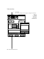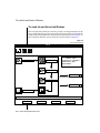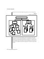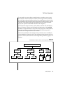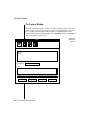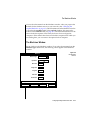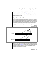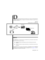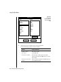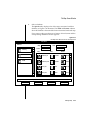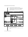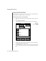
1
INFORMIX-Universal Server ® Guide to the High-Performance Loader Version 9.1 March 1997 Part No. 000-4820 Published by INFORMIX® Press Informix Software, Inc. 4100 Bohannon Drive Menlo Park, CA 94025 Copyright 1981-1997 by Informix Software, Inc. or their subsidiaries, provided that portions may be copyrighted by third parties, as set forth in documentation. All rights reserved. The following are worldwide trademarks of Informix Software, Inc., or its subsidiaries, registered in the United States of America as indicated by “®,” and in numerous other countries worldwide: INFORMIX; INFORMIX-OnLine Dynamic Server; DataBlade The following are worldwide trademarks of the indicated owners or their subsidiaries, registered in the United States of America as indicated by “®,” and in numerous other countries worldwide: Adobe Systems Incorporated: PostScript Hewlett-Packard Company: HP/9000 Intel Corporation: Intel International Business Machines Corporation: IBM; RS6000 Motorola Corporation: Motorola6800 SPARC International, Inc.: SPARCstation, licensed exclusively to Sun Microsystems, Inc. The Open Software Foundation: Motif; OSF/Motif; Open Software Foundation® X/Open Company Ltd.: UNIX; X/Open All other marks or symbols are registered trademarks or trademarks of their respective owners. Documentation Team: Twila Booth, Evelyn Eldridge-Diaz, Katherine Schaefer To the extent that this software allows the user to store, display, and otherwise manipulate various forms of data, including, without limitation, multimedia content such as photographs, movies, music and other large objects, use of any single large object may potentially infringe upon numerous different third-party intellectual and/or proprietary rights. It is the user's responsibility to avoid infringements of any such third-party rights. RESTRICTED RIGHTS/SPECIAL LICENSE RIGHTS Software and documentation acquired with US Government funds are provided with rights as follows: (1) if for civilian agency use, with Restricted Rights as defined in FAR 52.227-19; (2) if for Dept. of Defense use, with rights as restricted by vendor's standard license, unless superseded by negotiated vendor license as prescribed in DFAR 227.7202. Any whole or partial reproduction of software or documentation marked with this legend must reproduce the legend. ii Guide to the High-Performance Loader Table of Contents Table of Contents Introduction About This Manual . . . . . . . . . . . . . . Organization of This Manual . . . . . . . . . Types of Users . . . . . . . . . . . . . . Software Dependencies . . . . . . . . . . . Assumptions About Your Locale. . . . . . . . Demonstration Database . . . . . . . . . . Major Features . . . . . . . . . . . . . . . Documentation Conventions . . . . . . . . . . Typographical Conventions . . . . . . . . . Icon Conventions . . . . . . . . . . . . . Command-Line Conventions . . . . . . . . . Screen-Illustration Conventions . . . . . . . . Additional Documentation . . . . . . . . . . . On-Line Manuals . . . . . . . . . . . . . Printed Manuals . . . . . . . . . . . . . On-Line Help . . . . . . . . . . . . . . Error Message Files . . . . . . . . . . . . Documentation Notes, Release Notes, Machine Notes Compliance with Industry Standards . . . . . . . Informix Welcomes Your Comments . . . . . . . . Chapter 1 . . . . . . . . . . . . . . . . . . . . . . . . . . . . . . . . . . . . . . . . . . . . . . . . . . . . . . . . . . . . . . . . . . . . . . . . . . . . . . . . 3 3 5 5 5 6 6 7 7 9 10 12 13 13 13 14 14 15 15 16 . . . . . . . . . . . . . . . . . . . . . . . . . . . . . . . . . . . . 1-3 1-4 1-6 1-7 1-7 1-7 1-8 1-8 1-9 High-Performance Loader Overview Overview of Features of the HPL Data Load . . . . . . . . Data Unload . . . . . . . Loading Modes . . . . . . Deluxe Mode . . . . . Express Mode . . . . . The HPL Utilities . . . . . The onpload Utility . . . The ipload Utility . . . . . . . . . . . . . . . . . . . . . . . . . . . . . . . . . . . . . . . . . . . . . . . . . . . . . . . . . . . . . . . . . . . . . . . . . . . . . . . . . . . . . The onpload Database . . . . . . . . . . . . . . . The Relationship Among the Parts of the HPL. . . . . . . Environment Variables . . . . . . . . . . . . . . . . The DBONPLOAD Environment Variable . . . . . . . . The PLCONFIG Environment Variable . . . . . . . . . The Architecture of the onpload Utility . . . . . . . . . . Deluxe Mode Loads . . . . . . . . . . . . . . . . Express-Mode Loads . . . . . . . . . . . . . . . Unloads . . . . . . . . . . . . . . . . . . . . Chapter 2 Getting Started Data-Load Example . . . . . . . . . Start Universal Server . . . . . . . Create a File of Data . . . . . . . . Create a Database . . . . . . . . The ipload Utility . . . . . . . . . . Start the ipload Utility . . . . . . . Choose a Project . . . . . . . . . Check Your Defaults . . . . . . . The Load Job Windows . . . . . . . . The Load Job Select Window . . . . . The Load Job Window . . . . . . . The Device-Array Windows . . . . . . The Device Array Selection Window . . The Device-Array Definition Window . The Format Windows . . . . . . . . The Format Views Window . . . . . The Record Formats Window . . . . The Format-Definition Window. . . . The Filter, Discard Records, and Logfile Boxes The Filter Text Box . . . . . . . . The Discard Records Text Box . . . . The Logfile Text Box. . . . . . . . The Map Windows . . . . . . . . . The Map Views Window . . . . . . The Load Record Maps Window . . . The Map Definition Window. . . . . The Load Options Window . . . . . . . The Run Option . . . . . . . . . . The Active Job Window . . . . . . . . Verify the Data Transfer . . . . . . Perform a Level-0 Backup . . . . . . iv 1-9 1-10 1-12 1-12 1-13 1-13 1-14 1-16 1-18 Guide to the High-Performance Loader . . . . . . . . . . . . . . . . . . . . . . . . . . . . . . . . . . . . . . . . . . . . . . . . . . . . . . . . . . . . . . . . . . . . . . . . . . . . . . . . . . . . . . . . . . . . . . . . . . . . . . . . . . . . . . . . . . . . . . . . . . . . . . . . . . . . . . . . . . . . . . . . . . . . . . . . . . . . . . . . . . . . . . . . . . . . . . . . . . . . . . . . . . . . . . . . . . . . . . . . . . . . . . . . . . . . . . . . . . . . . . . . . . . . . . . . . . . . . . . . . . . . . . . . 2-3 2-4 2-4 2-4 2-5 2-5 2-6 2-6 2-7 2-7 2-10 2-10 2-11 2-12 2-13 2-13 2-15 2-17 2-19 2-19 2-19 2-19 2-20 2-20 2-23 2-23 2-28 2-29 2-30 2-31 2-31 Generate Example . . . . . . Start the Example . . . . . Prepare the Unload Job Window Perform the Unload . . . . Chapter 3 . . . . . . . . . . . . 2-31 . . . . . . . . . . . . 2-32 . . . . . . . . . . . . 2-32 . . . . . . . . . . . . 2-37 Using the High-Performance Loader Windows Using the HPL User Interface . . . . . . . . . Starting the User Interface . . . . . . . . . The HPL Main Window . . . . . . . . . . The Component-Selection Windows . . . . . The Component-Definition Windows . . . . . The Load Job and Unload Job Windows . . . . The Views Windows . . . . . . . . . . . The Selection-List Windows . . . . . . . . The Message Windows . . . . . . . . . . Using the HPL Buttons . . . . . . . . . . . Toolbar Buttons . . . . . . . . . . . . . Icon Buttons . . . . . . . . . . . . . . Buttons . . . . . . . . . . . . . . . Using the On-Line Help . . . . . . . . . . . Using UNIX Keyboard Commands to Move the Cursor Chapter 4 . . . . . . . . . . . . . . . . . . . . . . . . . . . . . . . . . . . . . . . . . . . . . . . . . . . . . . . . . . . . 3-3 3-4 3-4 3-7 3-10 3-14 3-15 3-19 3-20 3-20 3-21 3-29 3-31 3-33 3-33 Defining Projects The Project Organization . The Projects Window . Creating a New Project Selecting a Project . . Chapter 5 . . . . . . . . . . . . . . . . . . . . . . . . . . . . . . . . . . . . . . . . . . . . . . . . . . . . . . . . . . . . . . . . . . . . . . . . . . . 4-3 4-6 4-7 4-7 . . . . . . . . . . . . . . . . . . . . . . . . . . . . . . . . . . . . . . . . . . . . . . . . . . . . . . . . . . . . . . . . . . . . . . . . . . . . . . . . . . . . . . . . . . . . . . . . . . . . . . . . 5-3 5-3 5-4 5-5 5-5 5-5 5-7 5-8 5-8 5-10 5-10 5-11 5-12 Configuring the High-Performance Loader Configuring the ipload Utility . . . Selecting a Database Server . . . . Using the Connect Server Window Creating the onpload Database . Modifying the onpload Defaults . . The Defaults Window . . . . Changing the onpload Defaults . Selecting a Driver . . . . . . . The Drivers Window . . . . . Using the Drivers Window . . . Modifying the Machine Description . The Machines Window . . . . Using the Machines Window . . . . . . . . . . . . . . . . . . . . . . . . . . . . . . . . . . . . . . . . . Table of Contents v Chapter 6 Defining Device Arrays Device Arrays . . . . . . . . . . . . . . . . . . . Using Multiple Devices in a Device Array . . . . . . . . Using the Device Array Selection Window . . . . . . . . Using the Device-Array Definition Window . . . . . . . Chapter 7 Defining Formats Formats . . . . . . . . . . . . . . . . . . . . Fixed-Length Records . . . . . . . . . . . . . . . Creating a Fixed Format . . . . . . . . . . . . . Editing a Format . . . . . . . . . . . . . . . . Creating a Fixed Format That Uses Carriage Returns . . . Creating a Format That Includes Ext Type or Simple LO Data Delimited Records . . . . . . . . . . . . . . . . . Creating a Delimited Format . . . . . . . . . . . . Creating a Delimited Format That Includes Simple LOs . . Creating a Delimited Format That Includes Ext Types . . . COBOL Records . . . . . . . . . . . . . . . . . Creating a COBOL Format . . . . . . . . . . . . The Picture and Usage Descriptions . . . . . . . . . Other Formats . . . . . . . . . . . . . . . . . . Fast Format. . . . . . . . . . . . . . . . . . Fast Job . . . . . . . . . . . . . . . . . . . Format Options . . . . . . . . . . . . . . . . . . Modifying Fixed and COBOL Formats . . . . . . . . Modifying Delimited Format Options . . . . . . . . The Format Views Window . . . . . . . . . . . . . Chapter 8 Chapter 9 . . . . . . . . . . . . . . . . . . . . 7-3 7-4 7-5 7-9 7-11 7-12 7-16 7-16 7-17 7-18 7-19 7-20 7-20 7-21 7-21 7-21 7-22 7-22 7-24 7-26 Queries . . . . . . . . . . . . . . . . . . . . . Creating a Query . . . . . . . . . . . . . . . . . . Using the Table Button . . . . . . . . . . . . . . . Editing a Query . . . . . . . . . . . . . . . . . . Exporting and Importing Queries . . . . . . . . . . . . Importing a Query . . . . . . . . . . . . . . . . Exporting a Query . . . . . . . . . . . . . . . . The Database Views Window . . . . . . . . . . . . . . 8-3 8-4 8-7 8-13 8-13 8-13 8-15 8-17 Defining Queries Defining Maps Maps . . Load Maps vi 6-3 6-3 6-4 6-6 Guide to the High-Performance Loader . . . . . . . . . . . . . . . . . . . . . . . . . . . . . . . . . . . . . . . . 9-3 9-4 Using the Map-Definition Window Creating a Load Map . . . . . Unload Maps . . . . . . . . . Creating an Unload Map . . . Mapping Options . . . . . . . Using Mapping Options . . . . Setting the Mapping Options . . Editing Options . . . . . . . . Using the Delete Button . . . . Using the Find Button . . . . Using the Specs Button . . . . The Map Views Window . . . . . Chapter 10 . . . . . . . . . . . . . . . . . . . . . . . . . . . . . . . . . . . . . . . . . . . . . . . . . . . . . . . . . . . . . . . . . . . . . . . . . . . . . . . . . . . . . . . . . . . . . . . . . . . . . . . . . . . . . . . . . . . . . . . . . . . . . . . . . . . . 9-4 9-7 9-10 9-10 9-14 9-14 9-16 9-18 9-18 9-18 9-20 9-21 . . . . . . . . . . . . . . . . . . . . . . . . . . . . . . . . . . . . . . . . . . . . . . . . . . . . . . . 10-3 10-5 10-8 10-10 10-11 Components of the Unload Job . . . . . Choosing the Database Server . . . . Running Multiple Jobs . . . . . . The Unload Job Windows . . . . . . . Creating an Unload Job . . . . . . Running the Unload Job . . . . . . Using the Command-Line Information. Changing the Unload Options. . . . Editing an Unload Job . . . . . . The Generate Options . . . . . . . . . . . . . . . . . . . . . . . . . . . . . . . . . . . . . . . . . . . . . . . . . . . . . . . . . . . . . . . . . . . . . . . . . . . . . . . . . . . . . . . . . . . . . . . . . . 11-3 11-4 11-4 11-5 11-6 11-8 11-10 11-11 11-12 11-13 Components of the Load Job . . . . . . . . . . Choosing the Database Server . . . . . . . . Running Multiple Jobs . . . . . . . . . . Preparing User Privileges and the Violations Table The Load Job Windows . . . . . . . . . . . Creating a Load Job . . . . . . . . . . . Running the Load Job . . . . . . . . . . Using the Command-Line Information. . . . . Changing the Load Options . . . . . . . . . . . . . . . . . . . . . . . . . . . . . . . . . . . . . . . . . . . . . . . . . . . . . 12-3 12-4 12-4 12-4 12-7 12-8 12-10 12-12 12-13 Defining Filters Using a Filter . . . . . . . Creating a Filter . . . . . . Editing a Filter . . . . . . Filter Views . . . . . . . Filters with Code-Set Conversion Chapter 11 Chapter 12 . . . . . . . . . . Unloading Data from a Database Loading Data to a Database Table Table of Contents vii Editing a Load Job . The Generate Options . Chapter 13 Chapter 14 Chapter 15 . . . . . . . . . . . . . . . . . 12-15 . 12-15 Types of Generate Tasks . . . . . . . . . . . . . Generating from the Load Job Window . . . . . . . Using the Autogenerate Load Components Window . Generating from the Unload Job Window . . . . . . . Using the Autogenerate Unload Components Window Generating from the Components Menu . . . . . . . The Generate Window . . . . . . . . . . . . Generating Load and Unload Components . . . . . Using the No Conversion Job Option . . . . . . . . . . . . . . . . . . . . . . . . . . . . . . . . . . 13-3 13-4 13-4 13-6 13-6 13-10 13-10 13-13 13-14 . . . . . . . . The Browsing Options . . . . . . . . . . . . . . . . Previewing Data-File Records . . . . . . . . . . . . Reviewing Records That the Conversion Rejected . . . . . Viewing the Violations Table . . . . . . . . . . . . . Viewing the Status of a Load Job or Unload Job . . . . . . 14-3 14-3 14-6 14-7 14-9 Browsing Managing the High-Performance Loader . . . . . . . . . . 15-3 . . . . . . . . . . 15-4 . . . . . . . . . . 15-4 . . . . . . . . . . 15-9 . . . . . . . . . . 15-9 . . . . . . . . . . 15-10 . . . . . . . . . . 15-10 . . . . . . . . . . 15-10 . . . . . . . . . . 15-11 . . . . . . . . . . 15-12 . . . . . . . . . . 15-12 . . . . . . . . . . 15-13 . . . . . . . . . . 15-16 The onpload Utility Understanding the onpload Utility Starting the onpload Utility . Using the onpload Utility . . Syntax . . . . . . . . viii . . Generate Options Modes . . . . . . . . . . . . Deluxe Mode . . . . . . . . Express Mode . . . . . . . . Violations . . . . . . . . . . . Rejected Records from the Input File Constraint Violations . . . . . Viewing Error Records . . . . . Performance . . . . . . . . . . Configuration Parameters . . . . Mode . . . . . . . . . . . Devices for the Device Array. . . Usage Models . . . . . . . . Performance Hints . . . . . . Chapter 16 . . Guide to the High-Performance Loader . . . . . . . . . . . . . . . . . . . . . . . . . . . . . . . . . . . . . . . . . . . . . . . . 16-3 16-3 16-4 16-4 Appendix A The onpload Database The formats Table . The mapoption Table The query Table . . . . . . . . . . . . . . . . . . . . . . . . . . . . . . . . . . . . . . Appendix B The High-Performance Loader Configuration File Appendix C Picture Strings Appendix D Match Condition Operators and Characters Appendix E Custom Conversion Functions Appendix F Custom Drivers Appendix G The onstat -j Option Appendix H HPL Log-File and Pop-Up Messages . . . . . . . . . . . . . A-8 . A-11 . A-14 Index Table of Contents ix Introduction Introduction About This Manual . . . . . . . Organization of This Manual . . Types of Users . . . . . . . Software Dependencies . . . . Assumptions About Your Locale . Demonstration Database . . . . . . . . . . . . . . . . . . . . . . . . . . . . . . . . . . . . . . . . . . . . . . . . . . . . . . . . . . . . . . . . . . . . . . . . . . . 3 3 5 5 5 6 Major Features . . . . . . . . . . . . . 6 Documentation Conventions . . . . . . . Typographical Conventions . . . . . . Icon Conventions . . . . . . . . . . Comment Icons . . . . . . . . . Feature Icons . . . . . . . . . . Command-Line Conventions . . . . . . How to Read a Command-Line Diagram Screen-Illustration Conventions . . . . . . . . . . . . . . . . . . . . . . . . . . . . . . . . . . . . . . . . . . . . . . . . . . . . . . . . . . . . . . . . . . . . . 7 7 9 9 9 10 12 12 Additional Documentation . . . . . . . . . . . On-Line Manuals . . . . . . . . . . . . . Printed Manuals . . . . . . . . . . . . . On-Line Help . . . . . . . . . . . . . . Error Message Files . . . . . . . . . . . . Documentation Notes, Release Notes, Machine Notes . . . . . . . . . . . . . . . . . . . . . . . . . . . . . . 13 13 13 14 14 15 Compliance with Industry Standards . . . . . . . . . . . . 15 Informix Welcomes Your Comments . . . . . . . . . . . . . 16 . . . . . . . 2 Guide to the High-Performance Loader R ead this introduction for an overview of the information provided in this manual and for an understanding of the documentation conventions used. About This Manual The Guide to the High-Performance Loader describes how to use the HighPerformance Loader (HPL) to efficiently load and unload large quantities of data to or from an Informix database. This manual includes two tutorial examples that take you through the process of loading and unloading data. Organization of This Manual This manual includes the following chapters: ■ This Introduction provides an overview of the manual and describes the documentation conventions used. ■ Chapter 1, “High-Performance Loader Overview,” describes the architecture of the HPL and gives a general overview of the HPL and the tasks that it performs. It also explains the relationships and functions of the three parts of the HPL. ■ Chapter 2, “Getting Started,” uses two tutorials to introduce the user interface of the HPL and the ipload utility. ■ Chapter 3, “Using the High-Performance Loader Windows,” describes the basic graphical features of the user interface and the mechanics of how to use them. It includes information on basic features of the windows, buttons, on-line help, and keyboard commands. Introduction 3 Organization of This Manual 4 ■ Chapter 4, “Defining Projects,” describes the project as the primary organizational feature for organizing load and unload jobs and their respective components. It also describes how to create and manipulate a project. ■ Chapter 5 through 10 describe the various components that make up a load or unload job: device arrays, formats, queries, maps, and filters. Each chapter also describes how to create and modify the featured component. ■ Chapter 11 through 12 explain the process of performing an unload job and a load job. Each chapter describes the job window and the components that you must define before you can unload or load data. ■ Chapter 13, “Generate Options,” describes the generate feature, which you can use to quickly create the components of a load or unload job. It describes how to create the components using the Generate window. ■ Chapter 14, “Browsing,”describes the browsing options that you can use to examine files that the HPL creates. ■ Chapter 15, “Managing the High-Performance Loader,” discusses three aspects of managing the work you do with the HPL: modes, violations, and performance. ■ Chapter 16, “The onpload Utility,” describes the syntax of the onpload utility. ■ Appendix A describes the tables of the onpload database. ■ Appendix B describes the HPL configuration file. ■ Appendix C describes the two classes of picture strings that the HPL uses. ■ Appendix D describes the match conditions available in the HPL. ■ Appendix E and Appendix F describe how to build and integrate custom functions and drivers. ■ Appendix G describes the -j option (of the onstat utility) that provides special information about the status of an onpload job. ■ Appendix H provides explanatory notes and corrective actions for nonnumbered messages. Guide to the High-Performance Loader Types of Users Types of Users This manual is written for database administrators and Universal Server administrators who must load and unload large quantities of data in situations that require the following activities: ■ Loading external data or unloading data from a database ■ Moving data to a different computer or configuration ■ Altering the schema of a table If you have limited experience with relational databases, SQL, or your operating system, refer to Getting Started with INFORMIX-Universal Server for a list of introductory texts. Software Dependencies This manual assumes that you are using INFORMIX-Universal Server, Version 9.1, as your database server. In this manual, all instances of Universal Server refer to INFORMIX-Universal Server. Assumptions About Your Locale Informix products can support many languages, cultures, and code sets. All culture-specific information is brought together in a single environment, called a GLS (Global Language Support) locale. This manual assumes that you are using the default locale, en_us.8859-1. This locale supports U.S. English format conventions for dates, times, and currency. In addition, this locale supports the ISO 8859-1 code set, which includes the ASCII code set plus many 8-bit characters such as é, è, and ñ. If you plan to use nondefault characters in your data or your SQL identifiers, or if you want to conform to the nondefault collation rules of character data, you need to specify the appropriate nondefault locale(s). For instructions on how to specify a nondefault locale, additional syntax, and other considerations related to GLS locales, see the Guide to GLS Functionality. Introduction 5 Demonstration Database Demonstration Database The DB-Access utility, which is provided with your Informix database server products, includes a demonstration database called stores7 that contains information about a fictitious wholesale sporting-goods distributor. Sample command files are also included. Many examples in Informix manuals are based on the stores7 demonstration database. The stores7 database is described in detail and its contents are listed in Appendix A of the Informix Guide to SQL: Reference. The script that you use to install the demonstration database is called dbaccessdemo7 and is located in the $INFORMIXDIR/bin directory. For a complete explanation of how to create and populate the demonstration database on your database server, refer to the DB-Access User Manual. Major Features The HPL for Universal Server, Version 9.1, supports loading and unloading the following new Informix data types: INT8, LVARCHAR, SERIAL8, BLOB, BOOLEAN, CLOB, collection data types, distinct data types, opaque data types, and row types. The Introduction to each Version 9.1 product manual contains a list of major features for that product. The Introduction to each manual in the Version 9.1 Informix Guide to SQL series contains a list of new SQL features. Major features for Version 9.1 Informix products also appear in release notes. 6 Guide to the High-Performance Loader Documentation Conventions Documentation Conventions This section describes the conventions that this manual uses. These conventions make it easier to gather information from this and other Informix manuals. The following conventions are covered: ■ Typographical conventions ■ Icon conventions ■ Command-line conventions ■ Screen-illustration conventions Typographical Conventions This manual uses the following standard set of conventions to introduce new terms, illustrate screen displays, describe command syntax, and so forth. Convention Meaning KEYWORD All keywords appear in uppercase letters in a serif font. italics Within text, new terms and emphasized words appear in italics. Within syntax diagrams, values that you are to specify appear in italics. boldface Identifiers (names of classes, objects, constants, events, functions, program variables, forms, labels, and reports), environment variables, database names, filenames, table names, column names, icons, menu items, command names, and other similar terms appear in boldface. monospace Information that the product displays and information that you enter appear in a monospace typeface. (1 of 2) Introduction 7 Typographical Conventions Convention Meaning KEYSTROKE Keys that you are to press appear in uppercase letters in a sans serif font. ♦ This symbol indicates the end of feature-, product-, platform-, or compliance-specific information. ➞ This symbol indicates a menu item. For example, “Choose Tools➞Options” means choose the Options item from the Tools menu. (2 of 2) Tip: When you are instructed to “enter” characters or to “execute” a command, immediately press RETURN after the entry. When you are instructed to “type” the text or to “press” other keys, no RETURN is required. 8 Guide to the High-Performance Loader Icon Conventions Icon Conventions Throughout the documentation, you will find text that is identified by several different types of icons. This section describes these icons. Comment Icons Comment icons identify warnings, important notes, or tips. This information is always displayed in italics. Icon Description The warning icon identifies vital instructions, cautions, or critical information. The important icon identifies significant information about the feature or operation that is being described. The tip icon identifies additional details or shortcuts for the functionality that is being described. Feature Icons Feature icons identify paragraphs that contain feature-specific information. Icon Description GLS Identifies information that relates to the Informix Global Language Support (GLS) feature. These icons can apply to a row in a table, one or more paragraphs, or an entire section. A ♦ symbol indicates the end of the feature-specific information. Introduction 9 Command-Line Conventions Command-Line Conventions This section defines and illustrates the format of commands that are available in Informix products. These commands have their own conventions, which might include alternative forms of a command, required and optional parts of the command, and so forth. Each diagram displays the sequences of required and optional elements that are valid in a command. A diagram begins at the upper-left corner with a command. It ends at the upper-right corner with a vertical line. Between these points, you can trace any path that does not stop or back up. Each path describes a valid form of the command. You must supply a value for words that are in italics. You might encounter one or more of the following elements on a commandline path. Element Description command This required element is usually the product name or other short word that invokes the product or calls the compiler or preprocessor script for a compiled Informix product. It might appear alone or precede one or more options. You must spell a command exactly as shown and use lowercase letters. variable A word in italics represents a value that you must supply, such as a database, file, or program name. A table following the diagram explains the value. -flag A flag is usually an abbreviation for a function, menu, or option name or for a compiler or preprocessor argument. You must enter a flag exactly as shown, including the preceding hyphen. .ext A filename extension, such as .sql or .cob, might follow a variable that represents a filename. Type this extension exactly as shown, immediately after the name of the file. The extension might be optional in certain products. (.,;+*-/) Punctuation and mathematical notations are literal symbols that you must enter exactly as shown. (1 of 2) 10 Guide to the High-Performance Loader Command-Line Conventions Element Description ' ' Single quotes are literal symbols that you must enter as shown. A reference in a box represents a subdiagram. Imagine that the subdiagram is spliced into the main diagram at this point. When a page number is not specified, the subdiagram appears on the same page. Privileges p. 5-17 Privileges A shaded option is the default action. ALL Syntax within a pair of arrows indicates a subdiagram. The vertical line terminates the command. -f OFF ON , variable , 3 size A branch below the main path indicates an optional path. (Any term on the main path is required, unless a branch can circumvent it.) A loop indicates a path that you can repeat. Punctuation along the top of the loop indicates the separator symbol for list items. A gate ( 3 ) on a path indicates that you can only use that path the indicated number of times, even if it is part of a larger loop. Here you can specify size no more than three times within this statement segment. (2 of 2) Introduction 11 Screen-Illustration Conventions How to Read a Command-Line Diagram Figure 1 shows a command-line diagram that uses some of the elements that are listed in the previous table. Figure 1 Example of a Command-Line Diagram setenv INFORMIXC compiler pathname To construct a command correctly, start at the top left with the command. Then follow the diagram to the right, including the elements that you want. The elements in the diagram are case sensitive. Figure 1 diagrams the following steps: 1. Type the word setenv. 2. Type the word INFORMIXC. 3. Supply either a compiler name or pathname. After you choose compiler or pathname, you come to the terminator. Your command is complete. 4. Press RETURN to execute the command. Screen-Illustration Conventions The illustrations in this manual are generic renditions of various windowing environments. The details of specific dialog boxes, controls, and windows are deleted or redesigned to provide this generic look. Therefore, the illustrations in this manual depict the windowing environment a little differently than the way it appears on your screen. To familiarize yourself with this generic appearance, compare the generic windows and controls shown in Chapter 3, “Using the High-Performance Loader Windows,” to the windows and controls of the windowing environment in which you are operating the ipload utility. 12 Guide to the High-Performance Loader Additional Documentation Additional Documentation For additional information, you might want to refer to the following types of documentation: ■ On-line manuals ■ Printed manuals ■ On-line help ■ Error message files ■ Documentation notes, release notes, and machine notes On-Line Manuals A CD that contains Informix manuals in electronic format is provided with your Informix products. You can install the documentation or access it directly from the CD. For information about how to install, read, and print online manuals, see either the installation guide for your product or the installation insert that accompanies the documentation CD. The documentation set that is provided on the CD describes Universal Server, its implementation of SQL, and its associated application-programming interfaces. For an overview of the manuals in the Universal Server documentation set, see Getting Started with INFORMIX-Universal Server. Printed Manuals The Universal Server documentation set describes Universal Server, its implementation of SQL, and its associated application-programming interfaces. For an overview of the manuals in the Universal Server documentation set, see Getting Started with INFORMIX-Universal Server. To order printed manuals, call 1-800-331-1763 or send email to [email protected]. Introduction 13 On-Line Help Please provide the following information: ■ The documentation that you need ■ The quantity that you need ■ Your name, address, and telephone number On-Line Help The HPL on-line help facility provides a detailed, context-sensitive explanation of program functions. To invoke the on-line help, click Help in any window for window-specific help or choose options from the Help menu on the HPL main window. The Help menu lets you choose Glossary to view definitions that are related to the HPL or choose Contents to search for specific topics. Error Message Files Informix software products provide ASCII files that contain all the Informix error messages and their corrective actions. To read the error messages in the ASCII file, Informix provides scripts that let you display error messages on the screen (finderr) or print formatted error messages (rofferr). For a detailed description of these scripts, see the Introduction to the Informix Error Messages manual. The HPL log file stores nonnumbered messages that are returned by onpload during a data load or unload. For explanatory notes for the messages that appear in the log file, refer to Appendix H. 14 Guide to the High-Performance Loader Documentation Notes, Release Notes, Machine Notes Documentation Notes, Release Notes, Machine Notes In addition to printed documentation, the following on-line files, located in the $INFORMIXDIR/release/en_us/0333 directory, supplement the information in this manual. On-Line File Purpose HPLDOC_9.1 The documentation-notes file describes features that are not covered in this manual or that have been modified since publication. SERVERS_9.1 The release-notes file describes feature differences from earlier versions of Informix products and how these differences might affect current products. This file also contains information about any known problems and their workarounds. IUNIVERSAL_9.1 The machine-notes file describes any special actions that are required to configure and use Informix products on your computer. Machine notes are named for the product described. Please examine these files because they contain vital information about application and performance issues. Compliance with Industry Standards The American National Standards Institute (ANSI) has established a set of industry standards for SQL. Informix SQL-based products are fully compliant with SQL-92 Entry Level (published as ANSI X3.135-1992), which is identical to ISO 9075:1992, on INFORMIX-Universal Server. In addition, many features of Universal Server comply with the SQL-92 Intermediate and Full Level and X/Open SQL CAE (common applications environment) standards. Introduction 15 Informix Welcomes Your Comments Informix Welcomes Your Comments Please tell us what you like or dislike about our manuals. To help us with future versions of our manuals, we want to know about corrections or clarifications that you would find useful. Include the following information: ■ The name and version of the manual that you are using ■ Any comments that you have about the manual ■ Your name, address, and phone number Write to us at the following address: Informix Software, Inc. SCT Technical Publications Department 4100 Bohannon Drive Menlo Park, CA 94025 If you prefer to send email, our address is: [email protected] Or send a facsimile to the Informix Technical Publications Department at: 415-926-6571 We appreciate your feedback 16 Guide to the High-Performance Loader Chapter High-Performance Loader Overview 1 Overview of Features of the HPL . . . . . . . . . . . . . . 1-3 Data Load . . . . . . . . . . . . . . . . . . . . . . 1-4 Data Unload . . . . . . . . . . . . . . . . . . . . . 1-6 Loading Modes . . Deluxe Mode . Express Mode . . . . . . . . . . . . . . . . . . . . . . . . . . . . . . . . . . . . . . . . . . . . . . . . . . . . . . . 1-7 1-7 1-7 The HPL Utilities . . . . . . . . . . . The onpload Utility . . . . . . . . . The ipload Utility . . . . . . . . . . The onpload Database . . . . . . . . The Relationship Among the Parts of the HPL Distinctions Among the Parts of the HPL . . . . . . . . . . . . . . . . . . . . . . . . . . . . . . . . . . . . . . . . . . . . . . . . 1-8 1-8 1-9 1-9 1-10 1-11 Environment Variables . . . . . . . . The DBONPLOAD Environment Variable The PLCONFIG Environment Variable . . . . . . . . . . . . . . . . . . . . . . . . . . . . 1-12 1-12 1-13 The Architecture of the onpload Utility . . . Deluxe Mode Loads . . . . . . . . Threads That the onpload Utility Uses Threads That Universal Server Uses . Express-Mode Loads . . . . . . . . Unloads . . . . . . . . . . . . . . . . . . . . . . . . . . . . . . . . . . . . . . . . . . . . . . . . . . . . . . . . . . . . . . . . . . 1-13 1-14 1-15 1-16 1-16 1-18 1-2 Guide to the High-Performance Loader T his chapter introduces the High-Performance Loader (HPL), provides a general overview of the tasks that the HPL performs, and describes the architecture of the HPL. The chapter covers the theory of the HPL, but it does not attempt to describe how to use the HPL. Chapter 2 introduces the user interface, the ipload utility, that you can use to set the parameters for the HPL. Subsequent chapters provide details about the user interface. Overview of Features of the HPL The HPL is a feature of the INFORMIX-Universal Server that allows you to efficiently load and unload very large quantities of data to or from an Informix database. The HPL lets you exchange data with tapes, data files, and programs and converts data from these sources into a format compatible with an Informix database. The HPL also allows you to manipulate and filter the data as you perform load and unload operations. The HPL includes the following features: ■ The HPL supports COBOL, ASCII, multibyte, delimited, or binary data. You can add custom drivers to support other data types. ■ The HPL can load and unload data of a different GLS locale from that of the database server. ■ The client/server architecture of the HPL lets you use the ipload utility, a graphical user interface, on any computer on your network. ■ The ipload utility provides a Generate option that lets you automatically generate the HPL components that are required for a load or unload job. High-Performance Loader Overview 1-3 Data Load ■ The database-load feature lets you update your databases with data from any of the supported file types, while allowing you to control the format and selection of records from the input files. Data can be loaded from or unloaded to files, tapes, or application pipes, or to any combination of these three device types. ■ The HPL provides synonym support for tables that are valid for the local database server. You can use synonyms for both the load and unload operations. ■ The HPL provides support for unloading data with a query that accesses a view in its SELECT statement. ■ The load and unload operations run in the background of your multitasking UNIX system. Once the operation begins, you can continue to use ipload to perform other functions. ■ The HPL provides context-sensitive on-line help. The on-line help also includes a glossary. ■ Any Universal Server on your network can use the onpload database, which contains parameters and controls that the HPL uses. This accessibility allows centralized management of your load and unload controls. These parameters and controls include the HPL components such as formats, maps, and projects. Data Load The data-load process reads a source data file, converts the data to a different format, and inserts the converted data into a database table. The source data can come from one or more of the following sources: 1-4 ■ Files ■ Tapes ■ Pipes (application-generated data) Guide to the High-Performance Loader Data Load During conversion, the source data is often manipulated so that the converted data displays different characteristics. Examples of this manipulation include: GLS ■ changing lowercase letters to uppercase letters. ■ loading default values, loading certain table columns, or replacing nulls. ■ masking the data to include only part of a value. ■ converting from one data type to another, such as conversion of a numeric string to a float. ■ converting from the code set of one locale to the code set of another locale. ♦ When you prepare to run a data load using the HPL, you describe the actions that the HPL must take by defining a set of meta-data components. The components describe different aspects of the load process. Figure 1-1 illustrates the data load process. The HPL uses information from: ■ the device array to find the set of the source-data files. ■ the format to define the data types and layout of the source data. ■ the filter to select the records from the source data that should be written to the database table. ■ the map to modify and reorganize the data. The ipload utility helps you prepare the components. Chapter 12, “Loading Data to a Database Table,” addresses the process of loading a file to a database. Figure 1-1 The Data-Load Process Data files Format Input records Selected records Filter Table entries Map Device array High-Performance Loader Overview 1-5 Data Unload Data Unload The data-unload process is essentially the same as the load process, but in reverse. The data-unload process extracts the source data from one or more database tables; converts the data to a new format; and writes the converted data to a file, tape, or pipe (application). As in a load, you can manipulate the data from a database table so that the converted data displays different characteristics. Figure 1-2 illustrates how the components of the HPL affect the data as it moves from an Informix database to data files during the unload process. The HPL uses: ■ the query to select records from the database. ■ the map to reorganize or modify the selected records. ■ the format to prepare the records for writing out to the data files. ■ the device array to find the location of the data files. Figure 1-2 The Data-Unload Process Format Selected records Selected table Query Reorganized records Data files Map Device array The HPL uses the same components for an unload as for a load, with one exception. For an unload, the ipload utility creates a Structured Query Language (SQL) query that extracts selected data from the table. As with a load, unload components are grouped together into an unload job. Unload jobs can be saved, retrieved, and rerun as many times as necessary. Unload jobs can be grouped together with load jobs in the same project. For a description of the steps involved in an unload, refer to Chapter 11, “Unloading Data from a Database.” 1-6 Guide to the High-Performance Loader Loading Modes Loading Modes The HPL offers two load modes: deluxe and express. Express mode is faster and deluxe mode is more flexible. You can choose the mode that is best suited for your environment. For a detailed comparison between express and deluxe mode, refer to Chapter 15, “Managing the High-Performance Loader.” Deluxe Mode The deluxe mode updates indexes, performs constraint checking, and evaluates triggers as data is inserted into the table. Deluxe mode does not lock the table, so the loading of data can take place while other users are working. Deluxe mode is not as fast as express mode but allows table access and update during a load. Express Mode The express mode disables indexes, constraints, and triggers during the load. After the load, indexes are rebuilt and reenabled, constraints are evaluated and reenabled if possible, and triggers are reenabled. (The triggers are not evaluated with respect to the loaded data.) Express-mode loads are significantly faster than deluxe loads; however, no one can update the table or read the new data entries until the load is complete. High-Performance Loader Overview 1-7 The HPL Utilities The HPL Utilities The major parts of the HPL are as follows: ■ The onpload utility ■ The ipload utility ■ The onpload database The largest part of this manual discusses the HPL user interface, the ipload utility, because the user interface is the part that you see and with which you interact. However, the ipload utility is merely the interface that allows you to prepare the parameters (the onpload database) that the onpload utility uses to perform the data loads and unloads. Theoretically, you could use DB-Access or some other tool to populate the onpload database and never use ipload. However, ipload is a more efficient and accurate way to populate the onpload database. The onpload Utility The onpload utility performs the actual activity of converting and moving data. The onpload utility uses information from the onpload database to run the load or unload and to convert the data. The onpload utility performs conversion and filtering operations. During a load, onpload also records information about data records that do not meet the load criteria. One of the ipload options lets you start the onpload utility, so that you do not need to start the onpload utility from the command line. 1-8 Guide to the High-Performance Loader The ipload Utility The ipload Utility The ipload utility is a graphical interface that you use to create and store information for the onpload utility. The ipload utility lets you create, edit, and group the components of the load and unload. The ipload utility creates a database named onpload and stores information about the load components in the database. The onpload Database The onpload database contains information that the onpload utility requires to perform data loads and unloads. The onpload database can reside on any database server on your network. Also, any onpload utility can use the onpload database as long as the onpload utility can access the database server that contains the onpload database. In contrast, the onpload utility must run on the same computer as the database server that contains the target database. High-Performance Loader Overview 1-9 The Relationship Among the Parts of the HPL The Relationship Among the Parts of the HPL Figure 1-3 illustrates the relationship among the parts of the HPL. The ipload utility connects to the database server to populate the onpload database. The onpload utility uses the multithreaded architecture to make multiple connections to the database server and multiple I/O connections. “The Architecture of the onpload Utility” on page 1-13 describes in more detail how onpload works. Figure 1-3 Relationships Among the Parts of the HPL Tape Tape Tape onpload ipload Client/server connections Client/server connection Database server onpload database 1-10 Guide to the High-Performance Loader Target database The Relationship Among the Parts of the HPL You can start onpload in the following ways: ■ Using choices from the ipload interface ■ Using the onpload command When you start onpload from the ipload interface, ipload and onpload use a socket connection to send messages back and forth: start, stop, and simple reports. When you use the onpload command, onpload executes completely independently from ipload. The part of Figure 1-3 on page 1-10 to the right of the dashed line shows onpload loading or unloading data with no interaction from ipload. Distinctions Among the Parts of the HPL The following distinctions among the ipload utility, the onpload utility, and the onpload database are important: ■ The ipload utility manages the descriptions of load and unload jobs. It does not actively move data from one place to another. ■ The onpload utility moves data from one place to another (that is, from a database to a storage device, or from a storage device to a database). ■ The onpload database contains information that the onpload utility uses. The ipload utility manages the onpload database. Theoretically, you could manage the onpload database yourself and never use the ipload utility. However, that process would be very tedious and prone to errors. Informix strongly recommends that you use ipload. You can use DB-Access or other database tools to examine the contents of the onpload database, but always use ipload to modify the database. High-Performance Loader Overview 1-11 Environment Variables Environment Variables The HPL is part of INFORMIX-Universal Server, so you must start Universal Server before you use the HPL. Before you start Universal Server, you must set these environment variables: ■ INFORMIXDIR ■ ONCONFIG ■ INFORMIXSERVER ■ LD_LIBRARY_PATH The INFORMIXDIR, ONCONFIG, and INFORMIXSERVER environment variables are documented in the INFORMIX-Universal Server Administrator’s Guide. LD_LIBRARY_PATH is a new environment variable that is used on some computers for shared libraries. Refer to the machine notes for information about LD_LIBRARY_PATH. In addition to the environment variables that you must always set when you use Universal Server, the following environment variables refer to the HPL: ■ DBONPLOAD ■ PLCONFIG The DBONPLOAD Environment Variable Each database server can have only one active onpload database. In most cases, you can use the default onpload database, which is named onpload. If you choose to prepare multiple databases to hold different types of control information, you must set the DBONPLOAD environment variable before you can run a load or unload. 1-12 Guide to the High-Performance Loader The PLCONFIG Environment Variable To prepare multiple onpload databases 1. Set the DBONPLOAD environment variable to the name of the alternative onpload database. 2. Restart ipload. 3. Use ipload to prepare the alternative database. If you do not use an alternative onpload database, you do not need to set DBONPLOAD. The PLCONFIG Environment Variable The default configuration file for the onpload utility is plconfig.std. The configuration file always resides in the $INFORMIXDIR/etc directory. To use an alternative configuration file, you must set the PLCONFIG environment variable to the name of the alternative onpload configuration file. If you use plconfig.std, you do not need to set PLCONFIG. The onpload configuration file is described in Appendix B, “The HighPerformance Loader Configuration File.” The Architecture of the onpload Utility The greater part of this manual discusses the ipload utility; however, the ipload utility is merely the interface that allows you to prepare the parameters that the onpload utility uses. The onpload utility actually does the work of loading and unloading data. The onpload utility is a client application that attaches to INFORMIXUniversal Server. The utility is unusual because it uses the same multithreading architecture that Universal Server uses. By using multithreading, onpload can take advantage of parallel processing to do both I/O and data conversion as efficiently as possible. Multithreading is described in the INFORMIX-Universal Server Administrator’s Guide. The next sections describe how onpload uses multithreading for deluxe loads, express loads, and unloads. High-Performance Loader Overview 1-13 Deluxe Mode Loads Deluxe Mode Loads Figure 1-4 shows the threads that ipload uses in a deluxe-mode load process. In deluxe mode, data is subject to the same constraints as if you were loading the data using SQL INSERT statements. Figure 1-4 A Deluxe-Mode Load onpload utility Tape Tape tape I/O tape I/O sdriver sdriver convert convert convert convert convert convert worker worker pl_wkr_1 pl_wkr_2 cadiload cadiload Database server Buffer cache Table fragment 1-14 Guide to the High-Performance Loader Table fragment Table fragment Table fragment Deluxe Mode Loads Threads That the onpload Utility Uses The onpload utility starts the following threads: ■ tape I/O threads The onpload utility starts one tape I/O thread for each tape device. It handles reading of data from the tape device asynchronously. In the case of pipes input, a similar thread is started. In the case of disk file input, the multithreading AIO subsystem is used instead of a dedicated I/O thread. ■ sdriver threads The driver threads control I/O from input files. They handle device abstraction for the different device types handled. The driver threads also are responsible for passing out records from the input and passing records to the converters. ■ convert threads The onpload utility starts one or more convert threads for each device. These threads perform conversions on the input data such as uppercase to lowercase conversion or code-set conversion. ■ worker threads The onpload utility starts one worker thread for each input device. These threads communicate with the database server. The main responsibility of the worker thread is to pass data to the database server. To see the status of the onpload threads, you must use the -j option of the onstat utility. This option is documented in Appendix G. High-Performance Loader Overview 1-15 Express-Mode Loads Threads That Universal Server Uses Universal Server uses the following threads to insert the data into the database: ■ pl_wkr threads Each worker thread of the onpload utility is paired with a pl_wkr thread in the database server. These threads receive the data from onpload. If you look at a utility that shows Universal Server status, the pl_wkr threads are named pl_wkr_1, pl_wkr_2, pl_wkr_3, and so forth. ■ cadiload threads The cadiload threads are the insert threads. The insert threads perform a normal insert into the database, just as if you were using an INSERT statement. The SQL optimizer governs the method that is used for inserting the data. Express-Mode Loads Figure 1-5 on page 1-17 shows a single express-mode load process. In express mode, the data is inserted directly into an extent without any evaluation of objects (constraints, indexes, and/or triggers). The behavior of the onpload utility during an express load is the same as for deluxe loads, as described in “Threads That the onpload Utility Uses” on page 1-15. However, the behavior of the database server during an express load is quite different. The express load bypasses all of the SQL layer of the database server. The pl_wkr threads pass the data to stream threads (also called fragmenter threads) that decide where the data should be stored. The fragmenter threads pass the data to an exchange that distributes the data to setrw threads. The setrw threads write table rows to disk a page at a time, bypassing the buffer cache. The number of input devices can be different from the number of table fragments. The exchange operator handles multiplexing of data. The data is processed in parallel with respect to the data read from the device array and also with respect to the data written out to table fragments on separate disks. There is also pipeline parallelism in the data flow from input devices out to table fragments on disk. Parallelism is the main mechanism for achieving high performance. 1-16 Guide to the High-Performance Loader Express-Mode Loads Figure 1-5 An Express-Mode Load Tape Tape tape I/O tape I/O sdriver sdriver onpload utility convert convert convert convert convert convert worker worker pl_wkr_1 pl_wkr_2 stream_2.0 stream_2.1 Exchange Database server setwr_1.0 setwr_1.1 setwr_1.2 setwr_1.3 Table fragment Table fragment Table fragment Table fragment High-Performance Loader Overview 1-17 Unloads During express-mode load, the database server writes the data to new extents on disk, but those extents are not yet part of the table, as illustrated in Figure 1-6. At the end of express mode, the new extents are added to the table. Figure 1-6 Extents After an Express-Mode Load Extents of the target table Unattached extents during an express-mode load After the express-mode load, you must perform a level-0 backup before you can access the target database for writing. If you try to write to the table before you do a level-0 backup, the database server issues ISAM error -197, as follows: Partition recently appended to; can’t open for write or logging. ANSI If your database is ANSI compliant, all access (both read and write) is denied until you perform a level-0 backup. Because data is not logged in express mode, the level-0 backup is necessary to allow for recovery in case of media failure. ♦ Unloads Figure 1-7 on page 1-19 shows the onpload unload process. In the unload process, the behavior of onpload parallels the behavior described in “Threads That the onpload Utility Uses” on page 1-15 and “Threads That Universal Server Uses” on page 1-16, except that the threads are unloading the data instead of loading it. 1-18 Guide to the High-Performance Loader Unloads Figure 1-7 The Unload Procedure onpload utility Tape Tape tape I/O tape I/O sdriver sdriver convert convert convert convert convert convert ulworker ulworker pl_wkr_1 pl_wkr_2 ulstrm_1.1 ulstrm_1.2 Exchange Database server Query plan that SQL optimizer creates Table fragment Table fragment Table fragment Table fragment High-Performance Loader Overview 1-19 Unloads The ulstrm (unload-stream) thread packages data for output to the onpload client from the query plan. The SQL optimizer creates the query plan. The query plan behaves as if you were running a query from any other client, such as DB-Access. The exchange operator distributes the resulting data to the ulworker threads in a round-robin fashion, and onpload unloads the data onto tapes or files. Parallelism with respect to the output device, the source table fragments, and the flow of the data is evident in Figure 1-7 on page 1-19. 1-20 Guide to the High-Performance Loader Chapter Getting Started Data-Load Example . . Start Universal Server Create a File of Data . Create a Database . . . . . . . . . . . . . . . . . . 2 . . . . . . . . . . . . . . . . . . . . . . . . . . . . . . . . . . . . . . . . . . . . 2-3 2-4 2-4 2-4 The ipload Utility . . . . . . . . Start the ipload Utility . . . . . Choose a Project . . . . . . . Check Your Defaults . . . . . . Looking at the Defaults Window Looking at the Machines Window . . . . . . . . . . . . . . . . . . . . . . . . . . . . . . . . . . . . . . . . . . . . . . . . . . . . . . . . . . . . . . . . . . 2-5 2-5 2-6 2-6 2-6 2-6 The Load Job Windows . . . . The Load Job Select Window . The Load Job Window . . . . . . . . . . . . . . . . . . . . . . . . . . . . . . . . . . . . 2-7 2-7 2-10 The Device-Array Windows . . . . . . The Device Array Selection Window . The Device-Array Definition Window . . . . . . . . . . . . . . . . . . . . . . . . . . . . . . . 2-10 2-11 2-12 The Format Windows . . . . . The Format Views Window . The Record Formats Window . The Format-Definition Window . . . . . . . . . . . . . . . . . . . . . . . . . . . . . . . . . . . . . . . . 2-13 2-13 2-15 2-17 The Filter, Discard Records, and Logfile Boxes The Filter Text Box. . . . . . . . . The Discard Records Text Box . . . . . The Logfile Text Box . . . . . . . . . . . . . . . . . . . . . . . . . . . . . . . . . . . . . . . . . . . . 2-19 2-19 2-19 2-19 . . . . . . . . . . . . . . . . . . . . . . 2-2 The Map Windows . . . . . . The Map Views Window . . The Load Record Maps Window The Map Definition Window . . . . . . . . . . . . . . . . . . . . . . . . . . . . . . . . . . . . . . . . . . . . . . . . . . . . . 2-20 2-20 2-23 2-23 The Load Options Window . . . . . . . . . . . . . . . . 2-28 The Run Option . . . . . . . . . . . . . . . . 2-29 The Active Job Window . . . . . . . . . . . . . . . . . Verify the Data Transfer . . . . . . . . . . . . . . . . Perform a Level-0 Backup . . . . . . . . . . . . . . . 2-30 2-31 2-31 Generate Example . . . . . . Start the Example . . . . . Prepare the Unload Job Window Perform the Unload . . . . 2-31 2-32 2-32 2-37 . Guide to the High-Performance Loader . . . . . . . . . . . . . . . . . . . . . . . . . . . . . . . . . . . . . . . . . . . . . . . . . . . . . . . T his chapter guides you step-by-step through two examples that use the ipload utility. The first example moves data from a data file into a database table. The second example unloads data from an Universal Serverdatabase into a data file. The chapter is a tutorial; it assumes that you will execute each step as it is discussed. The purpose of this chapter is to illustrate quickly how the components of the High-Performance Loader (HPL) fit together. The chapter does not attempt to explain the components in any detail. After you complete these examples, you can refer to the later chapters in this book for more information about the options that are available for each of the procedures. Data-Load Example The illustrations in the first example use a database with only one table. The table contains three columns. The data to be loaded into the database is in a file that has only four records. In a real production environment, you would probably use the INSERT statement, the dbimport utility, or the LOAD statement for such a simple operation. However, by using an extremely simple example, the illustrations can show what happens at each step. Getting Started 2-3 Start Universal Server Start Universal Server The HPL, which includes the ipload utility, is part of Universal Server. Before you can use ipload, you must start Universal Server. Create a File of Data The illustrations in this chapter assume that the data to be loaded is in a file named /work/mydata. Create a file that contains the following data: 1|a|50 2|b|25 3|c|10 4|d|5 Create a Database The HPL loads data into an existing table in an existing database. The example in this chapter loads the information from the file /work/mydata into a threecolumn table named tab1 in a database named testdb. You can use DB-Access to prepare the database and table, as follows: CREATE DATABASE testdb; CREATE TABLE tab1 ( col1 INTEGER, col2 CHAR(1), col3 INTEGER ); GRANT ALL ON tab1 TO PUBLIC; GRANT CONNECT TO PUBLIC; After you finish preparing the database for the example, exit from DB-Access. 2-4 Guide to the High-Performance Loader The ipload Utility The ipload Utility The HPL uses information from the onpload database to control loading and unloading of data. Theoretically, you could create the onpload database and use DB-Access or some other database tool to populate it. However, Informix recommends that you always use ipload to manage the onpload database. Start the ipload Utility To start ipload, enter the following command at the command-line prompt: ipload The first time you start ipload, the utility automatically creates the onpload database. The ipload utility also puts certain default values into the database. Appendix A, “The onpload Database,” describes the database tables. When ipload starts, the High-Performance Loader main window (the HPL main window) appears, as Figure 2-1 illustrates. High-Performance Loader Jobs Browsers Components Configure Help Figure 2-1 The HPL Main Window Select Project <default> Project: <default> Server: svr1 Onpload Server: svr1 Tip: To exit from ipload, choose Exit from the Jobs menu. To continue with the example, do not exit. Getting Started 2-5 Choose a Project Choose a Project You use the HPL by preparing load jobs or unload jobs that import or export data. You can assign your load and unload jobs to various projects to organize the jobs into functional groups. Projects are described in Chapter 4, “Defining Projects.” The ipload utility automatically creates a project named <default>. If you choose not to organize your work into projects, you can put all of your load and unload jobs in the default project. For this example, you can use the default project. Click <default> on the HPL main window to choose the default project. Check Your Defaults The default values that ipload selects when it is first started specify machine type, character code set for character-type data, and other operating characteristics. In most cases, the only default that you might need to change is the machine type. Chapter 5, “Configuring the High-Performance Loader,” describes the ipload defaults. Looking at the Defaults Window Choose Configure➞Defaults to see the current default values. After you look at your defaults, you can click Cancel to exit from the Defaults window. If you need to change one of the default values, refer to “Modifying the onpload Defaults” on page 5-5. Looking at the Machines Window Choose Configure➞Machines to see the current default values. Make sure that the machine type displayed in the Machines window matches your current machine type. Click the Machine Type down arrow to select a machine type. If you need to change one of the values, refer to “Modifying the Machine Description” on page 5-10. Click Cancel to exit from the Machines window. 2-6 Guide to the High-Performance Loader The Load Job Windows The Load Job Windows A load job is a collection of the specific pieces of information that are required to move data from a data file into a database. The Load Job window, illustrated in Figure 2-3 on page 2-9, shows a flowchart that includes all of the components of a load job. After you become familiar with the ipload utility, you can create or modify the individual components of a load or unload job with direct menu choices from the HPL main window. The Load Job Select Window The data-load example in this chapter takes records from /work/mydata and loads them into tab1 of the testdb database. To perform the load, you need to create a load job. Getting Started 2-7 The Load Job Select Window To create a load job Choose Jobs➞Load from the HPL window. 1. The Load Job Select window appears, as Figure 2-2 illustrates. Figure 2-2 The Load Job Select Window Load Job Select Delete Notes Connect Selection Type Job Name: newjob Create Open Command Line: Job Information Job Type Status Server Map Datasource Notes Message: Enter a job name to create OK Cancel 2. Click Create in the Selection Type group. 3. Choose a name for the load job and type it in the Job Name text box. This example uses newjob. 2-8 Help Guide to the High-Performance Loader The Load Job Select Window 4. Click OK. The Load Job window appears, as Figure 2-3 illustrates. Figure 2-3 The Load Job Window Load Job Save As Notes Generate Job Name: newjob Onpload Server: onpload@svr1 Database Server: @svr1 Target Database: Format Device Filter Discard Records Map Logfile Options Table Message: Run Save Cancel Help Getting Started 2-9 The Load Job Window The Load Job Window The thick arrows on the Load Job window indicate the steps that you take as you build a load job. The icons indicate the task at each step. The thin arrows indicate filenames for error recording. To create a load job, you need to complete the following tasks: Task Click Specify the source of the data Device Describe the data Format Tell ipload which data you want to discard (optional) Filter Specify association between input fields and load-table columns Map Specify options for the load job Options Specify the database table to load Table Record rejected data records (optional) Discard Records Record information about the job (optional) Logfile The Device-Array Windows A device array is a collection of files, tape devices, and pipes that onpload uses for input and output. The Device Array Selection and device-array definition windows let you create a device array and specify the location of the input data. In this example, the input data is the /work/mydata file that you created in “Create a File of Data” on page 2-4. 2-10 Guide to the High-Performance Loader The Device Array Selection Window The Device Array Selection Window To create a device array Click Device in the Load Job window. 1. The Device Array Selection window appears, as Figure 2-4 illustrates. Figure 2-4 The Device Array Selection Window Device Array Selection Copy Delete Print Selection Type Create Open Device Array: an_array Current Arrays Notes Message: Enter a device array name to create OK 2. Cancel Help Click Create in the Selection Type group. Getting Started 2-11 The Device-Array Definition Window 3. Select a name for the device array and type it in the Device Array text box. This example uses an_array. 4. Click OK. The device-array definition window appears, as Figure 2-5 illustrates. The Device-Array Definition Window The title bar of the device-array definition window shows the array name that you typed in the Device Array text box. Figure 2-5 The Device-Array Definition Window with One Array Item an_array Print Notes Array Item Type Tape File Name: File Pipe Tape Parameters Block Size: Tape Size: MB Array Items Perform FILE /work/mydata Add Edit Delete Message: Select item to edit, or add new device item OK 2-12 Guide to the High-Performance Loader Cancel Help GB The Format Windows To add a device to the array 1. Click Add in the Perform group (lower right). 2. Click File in the Array Item Type group (upper left). 3. Type the full pathname of a device in the File Name text box. In this example, the device is /work/mydata. 4. Click Perform to add the /work/mydata file to the device array. The ipload utility lists each item of the device array in the Array Items list box. Figure 2-5 on page 2-12 shows the window after you add /work/mydata to the array. 5. Click OK. The display returns to the Device Array Selection window. 6. Click Cancel. The display returns to the Load Job window. The Device list box now displays the device array name that you chose. The Format Windows The format specifies the organization of the input data. In this example, the input data is in the file /work/mydata, which you created in “Create a File of Data” on page 2-4. Each record in the file has three fields. The Format Views Window The Format Views window displays existing formats, so that you can choose the format to use in the load job. Getting Started 2-13 The Format Views Window To open the Format Views window 1. Click the Format button in the Load Job window. The Format Views window opens, as Figure 2-6 illustrates. When you first start ipload, no formats are defined, as illustrated by the NONE FOUND icon. Figure 2-6 The Format Views Window Format Views Formats Search Load Maps Unload Maps NONE FOUND Message: Click on a format name to see maps which reference the format OK Create 2. 2-14 Cancel Help Click Create to open the Record Formats window. Guide to the High-Performance Loader The Record Formats Window The Record Formats Window Figure 2-7 shows the Record Formats window. The Record Formats window lets you create a new format or open an existing format. Figure 2-7 The Record Formats Window Record Formats Copy Delete Mode Print Search Formats Open Create Format: Create Format Type Type Fixed Delimited COBOL Notes Message: OK Cancel Help To create a new format 1. Click Create in the Mode group. 2. Click Delimited in the Type group. The input data file, /work/mydata, is in delimited format. Other formats are described in Chapter 7, “Defining Formats.” Getting Started 2-15 The Record Formats Window 3. Choose a name for your format and type it in the Create Format text box. This example uses the name a_format. 4. Click OK. The format-definition window opens. Figure 2-8 illustrates a partially completed format-definition window. The title bar of the format-definition window shows the name that you chose for the new format. Figure 2-8 The FormatDefinition Window Delimited Format—a_format Save As Print Name Notes Options Browse Type input2 Perform Chars Operation Chars input1 Add Insert Edit Delete Message: Please enter field specification OK 2-16 Guide to the High-Performance Loader Cancel Help The Format-Definition Window The Format-Definition Window In the format-definition window, you must make an entry for each field of the data records in the input file. The input file for this example (/work/mydata) has three fields of data in each record, so you must enter format information for three pieces of data. To enter a format definition 1. Click Add in the Operation group. 2. In the Name text box, type a descriptive name for the first field of the data record. You can choose any descriptive name. This example uses input1, input2, and input3 for the three fields of /work/mydata. 3. In the Type text box, type the type of the data. Because the data in /work/mydata is simple ASCII data, the type is Chars. Other data types are discussed in Chapter 7, “Defining Formats.” 4. Click Perform. Figure 2-8 on page 2-16 shows the format-definition window partially completed. The entry for the first item is complete. The Name and Type for the second item are present and ready for you to click Perform. 5. Repeat steps 2 through 4 for each of the three input fields. 6. Click OK after you complete all of the input fields. The display returns to the Format Views window. The window displays your new format in the Formats list box. 7. Click Cancel to return to the Load Job window. Getting Started 2-17 The Format-Definition Window The Load Job window now displays the name of your device and the name of your format, as Figure 2-9 illustrates. Figure 2-9 Partially Completed Load Job Window Load Job Save As Notes Generate an_array Device Job Name: newjob Onpload Server: onpload@svr1 Database Server: @svr1 Target Database: a_format Format Filter Discard Records Map Logfile Options Table Message: Run 2-18 Guide to the High-Performance Loader Save Cancel Help The Filter, Discard Records, and Logfile Boxes The Filter, Discard Records, and Logfile Boxes The Load Job window now has entries for a device and format. The next incomplete items on the pathway in the Load Job window (Figure 2-9 on page 2-18) are the Filter text box, the Discard Records text box, and the Logfile text box. The Filter Text Box Use a filter to choose the records from the data file that should be inserted into the table. In this example, all of the records from the /work/mydata data file will be inserted into the database table. Therefore, you do not need to create a filter. For this example, you can leave the Filter text box blank. Chapter 10, “Defining Filters,” describes how to create and use a filter. The Discard Records Text Box The Discard Records text box specifies a file that keeps information about records that were rejected because of incorrect format or invalid data. For this example, you can leave the Discard Records text box blank. “Reviewing Records That the Conversion Rejected” on page 14-6 describes how to view rejected records. The Logfile Text Box The Logfile text box specifies a file where a record of the load or unload job is kept. For this example, you can leave the Logfile text box blank. “Viewing the Status of a Load Job or Unload Job” on page 14-9 describes how to view the log file. Getting Started 2-19 The Map Windows The Map Windows The Map windows let you create a map that specifies which data field from the input file (/work/mydata) is entered into which columns in the database table. The Map Views Window The Map Views window lets you create a new map or edit an existing map. You need to create a map that describes how input data that is described by the record format a_format should be loaded into the table tab1. 2-20 Guide to the High-Performance Loader The Map Views Window To create a new map 1. Click the Map button in the Load Job window. The Map Views window appears, as Figure 2-10 illustrates. Figure 2-10 The Map Views Window Map Views Database Map: testdb Table: Format: a_format Map Search Table Format NONE FOUND Message: Click on database to expand view OK Create Cancel Help The NONE FOUND message in the Map column is appropriate. At this point, the Map Views window does not contain any information because you have not yet specified any relationships. Getting Started 2-21 The Map Views Window Click Create. 2. The Load Record Maps window appears, as Figure 2-11 illustrates. Figure 2-11 A Partially Completed Load Record Maps Window with an Open Selection List Load Record Maps Copy Delete Print Search Selection Type Open Current Maps Create Map Data Select From List Items tab1 Map Name: a_map Database: testdb Table: Format: a_format Notes Selection OK Message: Enter a map name to create OK 2-22 Cancel Guide to the High-Performance Loader Help Cancel The Load Record Maps Window The Load Record Maps Window The Load Record Maps window specifies the device array that holds the input data, the format that describes the input data, and the database and table where the input data will be stored. To complete the Load Record Maps window 1. Click Create in the Selection Type group. 2. Select a name for the map and type it in the Map Name text box. This example uses a_map. 3. Type the name of your database (testdb) in the Database text box. If you want, you can click the down arrow beside the Database text box and select a database from the selection list. 4. Click the down arrow beside the Table text box to see a list of tables in the selected database. Figure 2-11 on page 2-22 illustrates the Load Record Maps window and the selection list at this point. 5. Select a table from the list and click OK. Because you already filled in the Format text box on the Load Jobs window, the Format text box is already complete. 6. Click OK to open the map-definition window. The Map Definition Window The Map Definition window lets you associate an input item with a table column. This example stores the data from /work/mydata as follows, using the field names assigned on page 2-15. Data from Input Field Goes into Table Column input1 col3 input2 col2 input3 col1 Getting Started 2-23 The Map Definition Window Figure 2-12 shows the map-definition window. The title bar of this window shows the map name that you chose. Figure 2-12 The Map-Definition Window a_map Save As Notes Print Options Table: tab1 Delete Specs Find Table View Format: a_format col1 input1 col2 input2 col3 input3 Message: Drag and drop columns/fields between windows to assign data transfers between database/file Apply OK Cancel Help To associate each input item with a column of the database table 1. Click the col1 icon and hold the mouse button down. A box appears around the icon and its name. 2. 2-24 Drag the boxed icon to the input3 icon in the right-hand pane. Guide to the High-Performance Loader The Map Definition Window 3. Release the mouse button. The associated items appear in the second column of each pane. Figure 2-13 shows the map-definition window with this step completed. Figure 2-13 The Map-Definition Window with One Association Completed a_map Save As Notes Print Options Delete Specs Find Format View Format: a_format Table: tab1 input3 col1 input1 col2 input2 col1 col3 input3 Message: Drag and drop columns/fields between windows to assign data transfers between database/file Apply OK 4. Cancel Help Connect col2 to input2. Getting Started 2-25 The Map Definition Window 5. Connect col3 to input1. Figure 2-14 shows the window with all three connections completed. Figure 2-14 The Map-Definition Window with All Associations Completed a_map Save As Notes Print Options Delete Table: tab1 Specs Find Format View Format: a_format input3 col1 col3 input1 input2 col2 col2 input2 input1 col3 col1 input3 Message: Drag and drop columns/fields between windows to assign data transfers between database/file OK 2-26 Apply Cancel Help 6. Click OK to return to the Map Views window. 7. Click Cancel to return to the Load Job window. Guide to the High-Performance Loader The Map Definition Window The Load Job window now has entries in all of the required areas, as Figure 2-15 illustrates. The ipload utility was able to fill in the Table and the Target Database (upper right area) because you specified the database and table as you built the map. Figure 2-15 The Load Job Window with All Required Component Boxes Completed Load Job Save As Notes Generate an_array Device Job Name: Onpload Server: Database Server: Target Database: a_format Format newjob onpload@svr1 @svr1 testdb Filter Discard Records a_map Map Logfile tab1 Options Table Message: Run Save Cancel Help You have finished all of the required parts of the Load Job window, but you might want to modify the options, as discussed in the next section. Getting Started 2-27 The Load Options Window The Load Options Window The HPL has two modes of operation: express and deluxe. These modes are described in “Modes” on page 15-3. Briefly, the express mode is optimized for speed, whereas the deluxe mode provides the full functionality of SQL inserts as data is loaded. For a detailed comparison of these two modes, refer to Chapter 15, “Managing the High-Performance Loader.” This example uses the express mode. To set the load-job options 1. Click Options in the Load Job window. The Load Options window opens, as Figure 2-16 illustrates. Figure 2-16 The Load Options Window Load Options Load Mode: Express Generate Violations Records: Yes Tapes: 0 Number Records: 0 Start Record: 0 Max Errors: 0 Commit Interval: 0 Message: OK 2-28 Cancel Help 2. Select Express from the Load Mode list box. 3. Select No from the Generate Violations Records list box. 4. Make sure all of the other entries are 0. 5. Click OK to return to the Load Job window. Guide to the High-Performance Loader The Run Option The Run Option You are now ready to perform the load. To finish this example 1. Click Save to save the load job. After you save the load job, the message line displays the following message: Saved job successfully You can now execute the job, or you can return at a later time and execute the job. 2. Click Run to execute the load job. The Active Job window appears, as Figure 2-17 on page 2-30 illustrates. Tip: The ipload utility runs your job by generating an onpload command and then executing the command. To see the command that ipload generated, look at the Command Line text box on the Load Job Select window. For more information, refer to “Using the Command-Line Information” on page 12-12. Getting Started 2-29 The Active Job Window The Active Job Window The Active Job window reports the progress of your job. Figure 2-17 shows the Active Job window after the load has completed. Active Job Job Name: newjob Server: svr1 Figure 2-17 The Active Job Window Connecting to onpload, Please wait. . . Successful connection to onpload established Tue Jan 23 09:04:47 1996 SHMBASE CLIENTNUM Session ID 3 0x1a00000 0x49010000 Load Database Load Table Device Array Record Mapping Convert Reject -> testdb -> tab1 -> an_array -> a_map -> Database Load Completed -- Processed 4 Records Records Inserted -> 4 Detected Errors -> 0 Engine Rejected -> 0 Tue Jan 23 09:05:00 1996 Job Completed. . . connection closed Message: To interrupt and halt onpload session, click ‘Interrupt Job’ Interrupt Job OK Help When the Active Job window reports that the load job is complete, click OK to return to the Load Job Select or Unload Job Select window. 2-30 Guide to the High-Performance Loader Verify the Data Transfer Verify the Data Transfer If you want, you can use DB-Access to verify that the data from /work/mydata has been transferred into your database. Perform a Level-0 Backup The onpload utility does not log the data that it writes to a table during an express-mode load. For safety, onpload flags the dbspaces that are associated with the table as read-only. To allow for data recovery in case of disk corruption, you must make a level-0 backup. A level-0 backup on the dbspaces affected by the express-mode load saves the data and unsets the read-only flags. If you do not care about data recovery, you can make a level-0 backup using /dev/null as the backup device. This action unsets the read-only flag without backing up data to any real device. Generate Example The ipload utility has Generate options that you can use to automatically create a format, map, query, and device. After the components are generated, you can modify the components to meet your needs. The Generate options are described in Chapter 13, “Generate Options.” This example uses the Generate button in the Unload Job window to create the components that are required for an unload job. After you create the components, you can use the Run option to execute the unload job. Getting Started 2-31 Start the Example Start the Example If you completed the first example in this chapter, Universal Server and ipload are ready for you to use. If you did not complete the example, you need to complete the following tasks as the first example describes: ■ Start Universal Server (page 2-4) ■ Start the ipload utility (page 2-5) ■ Check your defaults (page 2-6) Prepare the Unload Job Window An unload job is a collection of the specific pieces of information that are required to move data from a database into a data file. The Unload Job window (Figure 2-3 on page 2-9) shows a flowchart that includes all of the components of an unload job. You can use the Generate option to create the components of the unload job and to complete the items on the Unload Job window. The generate example uses the Generate option to unload the contents of the items table of the stores7 database into a file named /work/items_out. (For instructions to create the stores7 database, refer to the Informix Guide to SQL: Reference.) To generate the unload job 1. Choose Jobs➞Unload from the HPL window. The Unload Job Select window appears, as Figure 2-18 on page 2-33 illustrates. 2. 2-32 Click Create in the Selection Type group. Guide to the High-Performance Loader Prepare the Unload Job Window Choose a name for the unload job and type it in the Job Name text box. 3. This example uses the name unld. Figure 2-18 The Unload Job Select Window Unload Job Select Delete Notes Connect Selection Type Job Name: unld Open Create Command Line: Job Information Job Type Status Server Map Datasource Notes Message: Enter a job name to create OK Cancel Help Getting Started 2-33 Prepare the Unload Job Window 4. Click OK. The Unload Job window appears, as Figure 2-19 illustrates. The information box in the upper right part of the display shows the name of the unload job, the name of the database server where the onpload database is stored, and the name of the database server where ipload is running. Figure 2-19 The Unload Job Window Unload Job Save As S Q Notes Generate Job Name: unld Onpload Server: onpload@svr1 Database Server: @svr1 Source Database: L Query Map Discard Records Format Logfile Options Device Message: Save Run 5. Cancel Help Click the Generate button. The Autogenerate Unload Components window appears. Figure 2-20 on page 2-35 shows the completed window. 2-34 Guide to the High-Performance Loader Prepare the Unload Job Window 6. Click Table. You can unload an entire database table or only selected records from the table. Table indicates that you want to unload the entire table. Query indicates that you want to unload selected records. 7. Type stores7 in the Database text box. For this step and steps 8 and 10, you can click the down arrow to the right of the text box and select your entry from a selection list. Figure 2-11 on page 2-22 shows an example of a selection list. 8. Type items in the Table text box. Figure 2-20 The Autogenerate Unload Components Window Autogenerate Unload Components Unload from Table Database: Query Table: stores7 items Query: Unload to Device Array /work/items_out File Message: Enter database to unload OK 9. Cancel Help Click File. File indicates that you want to enter the name of a file. If you choose Device Array, you must type the name of an already existing device array. 10. Type the full pathname of the file that will store the unloaded data. This file can be in any directory to which you have write access. 11. Click OK. Getting Started 2-35 Prepare the Unload Job Window The Generate option creates the Query, Format, and Map components for the unload job and fills in the Unload Job window. These components are all named unld. The Generate option also creates a device array named unld and puts the file that you specified (/work/items_out) into that array. Tip: After you finish this exercise, you can choose Components➞Devices from the HPL window and examine the unld device array. Figure 2-21 shows the Unload Job window as completed by the Generate option. Figure 2-21 The Unload Job Window Unload Job Save As S Q Notes L Generate unld Job Name: Onpload Server: Database Server: Source Database: unld Map Query unld unld onpload@svr1 @svr1 stores7 /tmp/unld.rej Discard Records Format /tmp/unld.log unld Logfile Options Device Message: Run 2-36 Guide to the High-Performance Loader Save Cancel Help Perform the Unload In addition to completing the main flow of the Unload Job window, the Generate option also fills in the Source Database information in the upper right-hand corner and creates pathnames for the Discard Records file and the Logfile. Chapter 14, “Browsing,” describes the rejected records file and the log file. Perform the Unload You are now ready to perform the unload. Tip: At this point, you might want to preview the records that the query will select. Refer to “Previewing Data-File Records” on page 14-3. To finish this example 1. Click Save to save the unload job. After you save the unload job, the Message line displays the following message: Saved job successfully You can now execute the job, or you can return at a later time and execute the job. 2. Click Run to execute the unload job. The Active Job window appears. This window reports the progress of your unload job. The Active Job window for an unload job is very similar to the Active Job window for a load job, which Figure 2-17 on page 2-30 illustrates. 3. When the Active Job window reports that the unload job is finished, click Cancel to return to the HPL main window. 4. You can create another job or choose Jobs➞Exit to leave the ipload utility. Getting Started 2-37 Chapter Using the High-Performance Loader Windows Using the HPL User Interface . . . . . . . Starting the User Interface . . . . . . . The HPL Main Window . . . . . . . . Initial Options on the HPL Main Window Options of the HPL Main Window . . . The Component-Selection Windows . . . The Toolbar Buttons . . . . . . . . The Selection Group . . . . . . . . The Component-Name Text Box . . . The Component List Box . . . . . . The Notes Area . . . . . . . . . The Message Line . . . . . . . . The Buttons. . . . . . . . . . . The Component-Definition Windows . . . The Toolbar Buttons . . . . . . . . The Item-Selection Group . . . . . . The Item-Name Text Box . . . . . . The Special-Parameters Group . . . . The Item List Box . . . . . . . . . The Perform Group . . . . . . . . The Message Line . . . . . . . . The Buttons. . . . . . . . . . . The Load Job and Unload Job Windows . . The Views Windows . . . . . . . . . Accessing Views Windows . . . . . Available Options in a Views Window . The Selection-List Windows . . . . . . The Message Windows . . . . . . . . . . . . . . . . . . . . . . . . . . . . . . . . . . . . . . . . . . . . . . . . . . . . . . . . . . . . . . . . . . . . . . . . . . . . . . . . . . . . . . . . . . . . . . . . . . . . . . . . . . . . . . . . . . . . . . . . . . . . . . . . . . . . . . . . . . . . . . . . . . . . . . . . . . . . . . . . . . . . . . . . . . . . . . . . . . . . . . . . . . . . . . . . . . . . . . . . . . . . 3 . . . . . . . . . . . . . . . . . . . . . . . . . . . . 3-3 3-4 3-4 3-5 3-5 3-7 3-9 3-9 3-9 3-9 3-10 3-10 3-10 3-10 3-12 3-12 3-12 3-12 3-13 3-13 3-13 3-13 3-14 3-15 3-15 3-16 3-19 3-20 3-2 Using the HPL Buttons . Toolbar Buttons . . . The Browse Button The Copy Button . The Delete Button. The Notes Button . The Print Button . Icon Buttons . . . . Buttons. . . . . . . . . . . . . . . . . . . . . . . . . . . . . . . . . . . . . . . . . . . . . . . . . . . . . . . . . . . . . . . . . . . . . . . . . . . . . . . . . . . . . . . . . . . . . . . . . . . . . . . . . . . . . . . . . . . . . . . . . . . . . . . . . . . . . . . . . . . . . . . . . . . . . . 3-20 3-21 3-22 3-23 3-25 3-26 3-28 3-29 3-31 Using the On-Line Help . . . . . . . . . . . . . . . . . 3-33 Using UNIX Keyboard Commands to Move the Cursor . . . . . . 3-33 Guide to the High-Performance Loader T his chapter describes the user interface (ipload) for the HPL. The chapter describes the basic features of the user interface and the mechanics of how to use them. The preceding chapter, “Getting Started,” gives simple examples that illustrate how the components of ipload interact.The following chapters give details about developing the onpload database by using the individual components of ipload. Appendix A, “The onpload Database,” describes the tables of the onpload database. This chapter discusses the following topics: ■ Using the HPL windows ■ Using the HPL buttons ■ Using on-line help ■ Using keyboard commands to move the cursor Using the HPL User Interface The ipload utility has the following types of displays that appear frequently: ■ HPL main window ■ Component-selection windows ■ Component-definition windows ■ Load Job and Unload Job windows ■ Views windows ■ Selection-list windows ■ Message windows Using the High-Performance Loader Windows 3-3 Starting the User Interface Starting the User Interface To start the user interface for the HPL, issue the following command at the system prompt: ipload After you issue the ipload command, a decorative splash screen appears that stays on the display while the ipload utility finishes loading. If you do not want to see the splash screen, use the -n flag, as follows: ipload -n The HPL Main Window When you start ipload, the High-Performance Loader main window (HPL main window) appears, as Figure 3-1 illustrates. The HPL main window is the focus of the user interface. You return to the main window after each task and choose a new option. High-Performance Loader Jobs Browsers Components Configure Help Select Project <default> Project: 3-4 Guide to the High-Performance Loader Server: svr1 Onpload Server: svr1 Figure 3-1 The HPL Main Window The HPL Main Window Initial Options on the HPL Main Window When you first enter ipload, most of the options on the HPL main window are disabled. You can take only the following actions: ■ You can select the default project in the Select Project list. ■ You can choose Configure➞Project to create a new project. For information on how to create a project, refer to “Creating a New Project” on page 4-7. ■ You can choose Configure ➞Server to select a database server and an onpload database server. For information about choosing a database server, refer to “Selecting a Database Server” on page 5-3. ■ You can choose Help to look at the on-line help. ■ You can choose Jobs➞Exit to exit from ipload. Options of the HPL Main Window After you select a project, you can choose options from any of the menus on the HPL main window. The following list describes each of the menu options. Main Menu Option Submenu Option Jobs Load Create a load job and use the Load Job window to load data into a database 12-3 Unload Create an unload job and use the Unload Job window to unload data from a database to a file 11-6 Exit Exit from the user interface 2-5 Record Review records in a specified format, search the list of available formats, or edit a format 14-6 Violations View records that passed the filter and conversion but were rejected by the database 14-7 Logfile View load status and see where any errors occurred 14-9 Formats Create or modify data-file formats 7-3 Browsers Components Refer to Page Purpose of the Selection (1 of 2) Using the High-Performance Loader Windows 3-5 The HPL Main Window Main Menu Option Configure Help Submenu Option Purpose of the Selection Refer to Page Maps Create or modify maps that show the relationship between data-file fields and database columns 9-3 Query Build, modify, or retrieve SQL-based queries 8-3 Filter Create or modify filters that determine source data-file records for conversion and load 10-3 Devices Specify a set of files, tapes, or pipes that will be read simultaneously for loading or unloading the database 6-3 Generate Job Automatically generate the components for load and unload jobs 13-3 Server Select the database servers that hold the onpload database and the target database 5-3 Project Create a project under which formats, filters, queries, maps, and load and unload jobs are stored 4-3 Defaults Specify the default character sets for the data file and databases 5-5 Driver Add a custom driver name and driver type to the list of standard drivers F-1 Machines Specify the machine parameters that are used to convert binary data 5-10 Glossary View definitions of terms that pertain to the HPL 3-33 Contents View the main contents page that directs you to discussions of various HPL topics 3-33 (2 of 2) 3-6 Guide to the High-Performance Loader The Component-Selection Windows The Component-Selection Windows The windows for creating or modifying components often (but not always) come in pairs. The first window, the component-selection window, lets you create a new component or select an existing component to modify. The first window also lets you view notes and copy, delete, or print information about a component. The second window, the component-definition window, lets you make the actual changes. The details of a selection window vary depending on the operation that you are performing. However, the component-selection windows have the following standard features: ■ Toolbar buttons ■ Selection group ■ Component-name text box ■ Component list box ■ Notes area ■ Message line ■ Buttons Using the High-Performance Loader Windows 3-7 The Component-Selection Windows Figure 3-2 shows the Device Array Selection window to illustrate the standard features of component-selection windows. Figure 3-2 The Device Array Selection Window Device Array Selection Toolbar buttons Copy Delete Print Selection group Selection Type Open Create Device Array: Component-name text box Current Arrays array_one cnvt894 largest Component list box personnel sales_sum_out Notes Notes area Message line Message: Select a device array name to open OK 3-8 Guide to the High-Performance Loader Cancel Help Buttons The Component-Selection Windows The Toolbar Buttons The buttons across the top of the display represent actions that you can take after you select a component from the component list. For example, in Figure 3-2 on page 3-8 (the Device Array Selection window), the toolbar buttons indicate that you can copy, delete, or print an array. “Using the HPL Buttons” on page 3-20 explains how to use these buttons. The Selection Group The selection group allows you to specify the action that you want to take. In most of the displays, you can either open an already existing component or create a new component. The Component-Name Text Box If you click Create in the selection group, you must type a name for the new component in the component-name text box. (In Figure 3-2 on page 3-8, you must give a name for the new Device Array.) Before you can type a name in the Device Array text box, you must click inside that text box to activate it. When the text box is active, it has a narrow black border. If you type a character that is not valid, the interface beeps at you, displays a message on the message line, and refuses to display the invalid character. The Component List Box The component list box lists the components that currently exist in this project. If you click Open in the selection group, you must select a component from this list. Using the High-Performance Loader Windows 3-9 The Component-Definition Windows The Notes Area The notes area displays stored comments about the selected component. This area is not an active area. To store a comment about a component, you must select a component and use the Notes button. For more information about notes, see “The Notes Button” on page 3-26. The Message Line The message line primarily gives instructions for the next logical action. The message line also gives an error message when an action fails or a completion message when a process is finished. The Buttons The buttons across the bottom of the display let you indicate your next action. For a more complete discussion, see “Using the HPL Buttons” on page 3-20. The Component-Definition Windows After you select a component to create or modify and then click OK in the component-selection window, you typically see the component-definition window. The component-definition window allows you to enter, edit, or delete values or items that describe the component.The device-array definition window has the following elements that are common to most of the other component-definition windows: 3-10 ■ Toolbar buttons ■ Item-selection group ■ Item-name text box ■ Special-parameters group ■ Item list box ■ Perform group ■ Message line ■ Buttons Guide to the High-Performance Loader The Component-Definition Windows Figure 3-3 shows an example of a component-definition window, the devicearray definition window. Figure 3-3 The Device-Array Definition Window array_one Toolbar buttons Print Notes Item-selection group Array Item Type Tape File Name: File Pipe /work/data/more_data Item-name text box Tape Parameters Block Size Tape Size MB Array Items GB Special parameters Items list box Perform FILE /work/data/some_data FILE /work/data/some_data Add PIPE /work/data/some_data Edit TAPE /work/data/some_data Message line Message: Enter file name to load from or to create OK Perform group Delete Cancel Help Buttons Using the High-Performance Loader Windows 3-11 The Component-Definition Windows The Toolbar Buttons The buttons across the top of the display represent actions that you can take after you select a component from the component list box. For example, in Figure 3-3 on page 3-11 (the device-array definition window), the toolbar buttons indicate that you can print or make a note about an item. “Using the HPL Buttons” on page 3-20 explains how to use these buttons. The Item-Selection Group The item-selection group lets you specify the type of item that you want to edit or the type of action that you want to take. After you specify a choice in the item-selection group, other options become active. In the device-array definition window, the item-selection group is labeled Array Item Type. After you select Tape, File, or Pipe, other options become active. The Item-Name Text Box The item-name text box lets you specify the name or description of one of the items that makes up the component. For example, in the device-array definition window, you type the full pathname of a device in the item-name text box. In the device-array definition window, the item-name text box is labeled Tape Name, File Name, or Pipe Name, depending on the type of component that you select from the Array Item Type group. The Special-Parameters Group When a component-definition window first appears, some of the choices are inactive (shown in gray letters). In general, the inactive choices are not meaningful until you specify some other characteristic of the component that you are editing. The special-parameters group in the device-array definition window (Figure 3-3 on page 3-11) is the Tape Parameters group. The items in the special-parameters group are meaningful only for tapes. The choices in the Tape Parameters group become active only if you select Tape from the Array Item Type group. The choices in Figure 3-3 are gray because File is selected in the Array Item Type group. 3-12 Guide to the High-Performance Loader The Component-Definition Windows The Item List Box The item list box shows items that you already created to define the component. In the device-array definition window, this list is labeled Array Items and shows the tapes, files, and pipes that are already part of the current device array. The Perform Group The Perform group lets you specify the action that you want to take. After you select an item and an action, you must click Perform to complete the action. For example, to add a new device in the device-array definition window, you must specify the name or description of the device and then click Perform to add it to the Array List. Important: Remember to click Perform to complete the action that you designated in the Perform group. The Message Line The message line primarily gives instructions for the next logical action. The message line also gives an error message when an action fails or a completion message when a process is finished. The Buttons The buttons across the bottom of the display let you indicate your next action. For a more complete discussion, see “Using the HPL Buttons” on page 3-20. Using the High-Performance Loader Windows 3-13 The Load Job and Unload Job Windows The Load Job and Unload Job Windows The Load Job and Unload Job windows provide a visual presentation of the basic components that you choose for each job. Figure 3-4 shows the Load Job window. The Load Job Window and its functions are discussed in Chapter 12. The Unload Job Window and its functions are discussed in Chapter 11. Figure 3-4 The Load Job Window Load Job Save As Notes Generate Job Name: newjob Onpload Server: onpload@svr1 Database Server: @svr1 Target Database: Format Device Filter Discard Records Map Logfile Options Table Message: Run 3-14 Guide to the High-Performance Loader Save Cancel Help The Views Windows The Views Windows A views window shows a graphic representation of the relationships among various ipload components. From a views window, you can search for specific components, select an existing component for editing, or create a new component. A views window does not allow you to change any values. To change values of a component, you must display a component-definition window. Accessing Views Windows The following table lists the four types of views windows and gives instructions for how to access each view. Refer to Page Window Name Purpose How to Access Format Views Show the load and unload maps that are associated with a particular format ■ Click Search in the Record Formats window ■ Click Format in the Load Job window* ■ Click Format in the Unload Job window* ■ Click Search in the Load Record Maps window 9-21 ■ Click Search in the Unload Record Maps window 9-11 ■ Click Map in the Load Job window* ■ Click Map in the Unload Job window* Show the tables in the database or the queries that are associated with the database ■ Click Search in the Query window ■ Click Table in the Load Job window* ■ Click Query in the Unload Job window* Show the formats that are associated with a particular filter ■ Click Search in the Filter window ■ Click Filter in the Load Job window* Map Views Database Views Filter Views Show the databases, tables, queries, and formats that are associated with a map 2-13 8-5 10-10 * These options display the View window only if the corresponding text box is empty. If the text box *includes the name of a component, the component-definition window is displayed. Using the High-Performance Loader Windows 3-15 The Views Windows Available Options in a Views Window The four types of Views windows operate in a similar manner. When a Views window appears, you have the following options: ■ Type in a component name and search for the component. ■ Click a label associated with an icon to expand the view and see related components. ■ Click an icon to open the component-definition window that allows you to edit the component values. ■ Click Create to display the component-selection window that allows you to create a new component. Searching for a Component You can use the Search button in a Views window to locate a specific component. Type the component name in the search text box and then click Search. The view displays only the component names that match the text string. You can use the following wildcard search characters in the search text string. Wildcard Symbol Effect ? Matches any single character * Matches any string of characters For example, type unj100? to display components that are named unj100a, unj100b, unj1001, and so on. The expression unj100? does not match unj100aaa, unj100ab, or unj10015. However, the expression unj100* does match unj100aaa, unj100ab, or unj10015 because the * symbol matches multiple characters. 3-16 Guide to the High-Performance Loader The Views Windows Expanding the View Three of the views windows expand their views to show related components. To expand the view, click an icon label (for example, customer_del) in the first pane. In the Database Views window, you can expand the view further by clicking an icon label in the second pane. Figure 3-5 shows the Format Views window. Figure 3-5 The Format Views Window Format Views Formats Search Load Maps Unload Maps customer_del items_fixed Message: Click on a format name to see maps which reference the format OK Create Icon Cancel Help Icon label Using the High-Performance Loader Windows 3-17 The Views Windows When you click an icon label in the Formats pane, the view expands to show maps that are related to your choice. Figure 3-6 shows the expanded view. Figure 3-6 Expanded View of a Format Format Views Formats Search Load Maps customer_del Unload Maps customer_del customer_del items_fixed Message: Click on a format name to see maps which reference the format OK Create Cancel Help You can click the desired icon to display a definition window for any format or map that is shown. 3-18 Guide to the High-Performance Loader The Selection-List Windows The Selection-List Windows A selection-list window lists the possible values for a text box. A down arrow that follows a text box indicates that you can use a selection list to see and select possible values for the text box. When you click the down arrow, the corresponding selection-list window appears. Figure 3-7 shows the selection list that is available for the Machine Type text box in the Defaults window. After you select an item in the list box, click OK, and the item appears in the text box on the original window. Figure 3-7 The Defaults Window and a Selection List Defaults Defaults for Server Server Name: default Machine Type: Sparcstation Data Code Set: ASCII Database Code Set: Arrow buttons Select From List Items Intel ASCII Sparcstation Message: Select specific server or ‘default’ OK Apply Cancel Sequent Help Selection list RS6000 HP/9000 Motorola6800 Selection Sparcstation OK Cancel Tip: If your entry is rejected, look at the selection list. Your entry is invalid if it is not available in the selection list. Selection-list windows are available for many text boxes throughout the HPL user interface. These windows have various names, but this document refers to them as selection lists. Using the High-Performance Loader Windows 3-19 The Message Windows The Message Windows A message window typically contains either a warning or an information update. A warning lets you verify or cancel the action that you have just chosen. An update informs you about the successful completion of an operation or explains why an operation failed. Figure 3-8 illustrates a typical error message. Message Error -1 connecting to server judith_shm! Figure 3-8 The Message Window OK Using the HPL Buttons Once you move beyond the HPL main window, every window has at least one button to help you move through the interface. In general, buttons appear in three locations: 3-20 ■ Toolbar buttons appear across the top of the display. ■ Icon buttons appear in the middle section of the display. ■ Buttons appear across the bottom of the display. Guide to the High-Performance Loader Toolbar Buttons Toolbar Buttons Toolbar buttons appear at the top of many windows. The function of the window determines which buttons appear. The following sections describe the toolbar buttons. Buttons that appear in only one window are described with the specific window. Button Button Name Purpose Refer to Page Browse Displays the Browse window 14-3 Copy Copies the selected component (format, map, query, filter, device, or project) to a new item 3-23 Connect Lets you reattach to an active unload (or load) job from the Unload (or Load) Job Select window 12-8 Delete (trashcan) Deletes the selected component (format, map, and so on) 3-25 Delete (eraser) Breaks the association between a database column and a data-file field 9-18 File Displays the Import/Export File Selection Window 8-13 Find Allows you to quickly locate a particular field or column in a map window 9-18 (1 of 2) Using the High-Performance Loader Windows 3-21 Toolbar Buttons Button Button Name Purpose Refer to Page Generate Lets you generate jobs automatically 13-3 Notes Allows you to type descriptive text for an item 3-26 Options Displays an options window where you can change default values or supply additional parameters 11-11, 12-13 Print Prints the parameters for the selected item 3-28 Save As Saves a copy of the currently selected item (behaves in the same way as the Copy button) 3-23 Search Displays the Views window where you can see the relationships among components 3-15 Specs Displays the Specifications window, where you can view the attributes for selected columns or fields 9-20 (2 of 2) The Browse Button The Browse button lets you look through the files that show information about the load or unload jobs and any problems that the onpload utility found. For more information about the Browse button, refer to “The Browsing Options” on page 14-3. 3-22 Guide to the High-Performance Loader Toolbar Buttons The Copy Button The Copy button lets you copy a selected component. This feature can save you time when you are creating a new component. You can copy an existing component and then modify the copy with your changes. You can copy one component at a time, or you can select and copy multiple components at the same time. You can copy components that are grouped under a project (filters, formats, maps, and queries) within the same project or to a different project. If you copy a component within a project, you must give the copy a different name. If you copy a component to a different project, you can retain the name for the copy or give the copy a different name. If you copy multiple components, you must copy them to a different project. When you copy multiple components, the components retain their names. Important: Devices are not project specific. When you copy a device, you must give the copy a new name. To copy an existing format to a new format 1. In the HPL main window, select the project that includes the format that you want to copy. 2. Choose Components➞Formats to access the Record Formats window. For an example, see “Creating a Fixed Format” on page 7-5. 3. Select the format that you want to copy. This example assumes that the format to copy is some_format. Using the High-Performance Loader Windows 3-23 Toolbar Buttons 4. Click the Copy button. The Copy Data window appears, as Figure 3-9 illustrates. The Copy Data window displays a list of existing projects. The Copy To text box shows the name of the format that you are copying. Figure 3-9 The Copy Data Window Copy Data Projects <default> practice stores7 Copy To: some_format Message: Select a destination project OK Cancel Help 5. Select the project to which you want to copy the format. 6. Type the name that you want to give to the copied format in the Copy To text box. If you are copying the format to another project, you can keep the same name. You must change the name, however, if you are copying the format to the same project. 7. Click OK. The display returns to the Record Formats window. 8. 3-24 Click Cancel to return to the HPL main window. Guide to the High-Performance Loader Toolbar Buttons The Delete Button The Delete button lets you delete one or more selected components. To delete an existing format 1. In the HPL main window, select the project that includes the format that you want to delete. 2. Choose Components➞Formats to access the Record Formats window. For an example, see “Creating a Fixed Format” on page 7-5. 3. Select the format that you want to delete. 4. Click the Delete button. The Confirm Delete window appears, as Figure 3-10 illustrates. The Confirm Delete window describes the impact of deleting this format. The text in this window is different for each of the component types. Figure 3-10 The Confirm Delete Window PLEASE CONFIRM FORMAT(S) DELETE! Deleting a Format will additionally remove: (1) Filters associated with the format (2) Maps associated with the format (3) Jobs associated with the deleted Maps OK 5. Cancel Help Click OK to confirm the deletion, or click Cancel to cancel it. If you click OK, the format is deleted, as well as any associated maps, filters, and jobs. 6. Click Cancel to return to the HPL main window. Using the High-Performance Loader Windows 3-25 Toolbar Buttons The Notes Button The Notes button lets you type descriptive text for an item. The text of the note is displayed in the Notes area in a window when you select the item. The Notes feature is a useful tool for identifying ipload components, load jobs, unload jobs, and projects. To create a note 1. Click the Notes button in a component-definition window. The Notes window appears, as Figure 3-11 illustrates. Figure 3-11 The Notes Window Notes Create Date: 04/06/1995 Modification Date: 04/06/1995 This note is associated with the “authors” format. OK Cancel 2. Type the descriptive text in the Notes text box. 3. Click OK to store the note and return to the component-definition window. When you select the component, the note text is displayed in the Notes area. 3-26 Guide to the High-Performance Loader Toolbar Buttons If you do not make any changes to a note, click Cancel instead of OK. For example, the note created in Figure 3-11 on page 3-26 is associated with the authors format. The next time you go to the Record Formats page and select authors, ipload displays the note text, as Figure 3-12 illustrates. Figure 3-12 The Record Formats Window with Notes Text Record Formats Copy Delete Print Search Formats Mode Open Open Format: authors Create Type Fixed Delimited Format authors characters plot plot_copy Type Fixed Delimited Fixed Fixed COBOL Notes This note is associated with the “authors” format. Message: OK Cancel Help The ipload utility stores the information that you type in the Notes window in the note table of the onpload database. For a description of the note table, refer to “The note Table” on page A-13. Using the High-Performance Loader Windows 3-27 Toolbar Buttons The Print Button The Print button lets you print information that is associated with a component. Before you start ipload, you must set your workstation so that it can find a printer. For information about setting up a printer, refer to your operating-system manuals. If you click the Print button in the map-definition window in Figure 2-14 on page 2-26, the following printout results: ------------------------------------------------------------------------------LOAD MAP REPORT ------------------------------------------------------------------------------Project Name : <default> : a_map OPTIONS Database Table ------------ -----------testdb tab1 Format -------------a_format RECORD FORMAT MAP VIEW Format Field -------------------------input1 input2 input3 3-28 Guide to the High-Performance Loader Table Column Option Data ----------------------- -------------------col3 col2 col1 Icon Buttons Icon Buttons Icon buttons appear in the middle sections of the Load Job and Unload Job windows and Views windows. The icon buttons represent various components. When you click it, each button opens another display. The following table shows and describes the icon buttons that are used in these windows. Component Description Window Action The device or device array where the source files are located Load Job ■ If the text box is empty, click the Device button to display the Device Array Selection window, where you can create or open a device type. ■ If the text box has an entry, click the Device button to display the device-array definition window for that specific device or type the name of a different device in the text box. The filter that controls which records are selected from the data file for a database update (The use of a filter is optional.) Load Job ■ If the text box is empty, click the Filter button to display the Filter Views window, where you select a filter and associated format. You can also create a filter from this window. ■ If the text box has an entry, click the Filter button to display the filter-definition window for that specific filter or type the name of a different filter in the text box. ■ In the Filter Views window, click the Filter button to display the filter-definition window for a specific filter. Unload Job Device Filter Filter Views (1 of 3) Using the High-Performance Loader Windows 3-29 Icon Buttons Component Description Window Action The format of the source data used for this load or unload Load Job ■ If the text box is empty, click the Format button to display the Format Views window, where you can select a format and associated map. You can also create a format from this window. ■ If the text box has an entry, click the Format button to display the format-definition window for that specific format or type the name of a different format in the text box. ■ In all Views windows, click the Format button to display the format definition for a specific format. In these windows, the button shows only one of the three symbols (F, D, C) to indicate whether the type of format is fixed, delimited, or COBOL. ■ If the text box is empty, click the Map button to display the Map Views window, where you can select a map and associated table and format. You also can create a map from this window. ■ If the text box has an entry, click the Map button to display the map-definition window for that specific map or type the name of a different map in the text box. ■ In a Views window, click the Map button to display the map-definition window for a specific map. ■ Click the Options button to display the Mapping Options window. For a discussion of these options, refer to “Changing the Load Options” on page 12-13. Unload Job Format The map that correlates fields of the data source to database columns Map Load Job Unload Job Map Views Format Views Database Views The options that let you specify characteristics of the load or unload Load Job Unload Job Options (2 of 3) 3-30 Guide to the High-Performance Loader Buttons Component S Q L Description Window Action The query that selects data from the database table Unload Job ■ If the text box is empty, click the Query button to display the Database Views window from which you can select the table and associated map and format. ■ If the text box has an entry, click the Query button to display the query-definition window for that specific query or type the name of a different query in the text box. ■ In a Views window, click the Query button to display the query-definition window for a specific query. ■ Click the Table button to display the Database Views window from which you can select the table and associated map and format. If an association is not apparent, click Create to create one. ■ Click the Table button in the query definition window to choose a table and columns for the Select entry. Database Views Map Views Query The database table into which the converted data will be loaded Load Job Database Views Query Definition Table (3 of 3) Buttons The buttons across the bottom of the display let you indicate the next action. Most windows have one or more of the following buttons. Button Action Apply Save changes but do not exit. Cancel Do not save any changes. Exit to the previous display. (1 of 2) Using the High-Performance Loader Windows 3-31 Buttons Button Action Create Display the component-selection window. Help Display context-sensitive help in a separate window. For information about the on-line help, see “Using the On-Line Help” on page 3-33. OK Save changes and exit to the previous display. (2 of 2) Use OK only when you have actually made a change on the display. If you are exiting from a series of displays, use Cancel to exit from the display. Figure 3-13 illustrates the use of OK and Cancel. Figure 3-13 Using OK and Cancel from the HPL Main Window Choose Components➞Device to open the Device Array Selection window. Select a device array. Click OK to open the devicearray definition window. Device Array Selection window HPL Main window Click Cancel to exit from the Device Array Selection window and return to the HPL main window. 3-32 Guide to the High-Performance Loader Device-array definition window Edit the array. Click OK to record the changes and return to the Device Array Selection window. Using the On-Line Help Using the On-Line Help The Help menu on the HPL main window has the following choices: ■ Glossary ■ Contents The Glossary option opens a scrolling list of items. Select an item to see its definition. The Contents option takes you to the main contents page. This page directs you to discussions of various HPL topics. If you click Help in any window other than the HPL main window, Help displays information that is related to the current window. After the Help window opens, you can click its Help button for more information about using the Help window. Using UNIX Keyboard Commands to Move the Cursor Instead of using the mouse to move from area to area in the HPL user interface, you can use keyboard commands to move the cursor. As you move around, the currently selected item is highlighted with a box. The following table lists the cursor-moving keystrokes. Keystroke Result TAB Move from area to area. Sometimes used to move from tab stop to tab stop. SHIFT-TAB Back up; that is, move from area to area in reverse order. CONTROL-TAB Move from area to area when TAB is reserved to move from tab stop to tab stop. Cursor keys Move from item to item within a functional area. SPACEBAR Select the current item or action. Using the High-Performance Loader Windows 3-33 Using UNIX Keyboard Commands to Move the Cursor Most displays in the HPL user interface are divided into functional areas, such as toolbar buttons, selection group, component-name text box, component list box, and so on. Depending on the nature of the specific display, sometimes TAB moves from item to item (or even from tab stop to tab stop) within a major area. On other displays, TAB moves only between functional areas, and you must use SPACEBAR to move around within the functional area. 3-34 Guide to the High-Performance Loader Chapter Defining Projects The Project Organization . The Projects Window . Creating a New Project Selecting a Project . . . . . . . . . . . . . . . . . . . . . . . . . . 4 . . . . . . . . . . . . . . . . . . . . . . . . . . . . . . . . . . . . . . . . 4-3 4-6 4-7 4-7 4-2 Guide to the High-Performance Loader T he HPL lets you organize your work by specifying projects. A project is a collection of individual pieces that you use to load and unload data. A project can include load and unload jobs and the maps, formats, filters, and queries that you use to build the load and unload jobs. This chapter explains how to create a project and how projects are related. The individual components that you store in projects are described in later chapters. The Project Organization The HPL uses only one database, onpload, to keep track of the preparation that you do for loading and unloading data. Using projects lets you organize your work into functional areas. For example, you might regularly transfer data to or from several unrelated databases. You could put all of the preparation for each database into a separate project. When you first start the ipload utility, ipload creates a project named <default>. If you prefer, you can select the <default> project and assign all of your work to that project. The HPL does not require that you create any additional projects. However, creating projects and putting separate tasks into distinct projects makes your work easier to maintain. Defining Projects 4-3 The Project Organization Figure 4-1 shows the relationships among projects, jobs, and components. Figure 4-1 Illustration of Project Hierarchy High-Performance Loader Project two Project one Job one_1 (table1) Job one_2 (table 2) Query Format Filter Job two_1 (table A) Query Map Format Job two_2 (table A) Filter Map Format Format Map Map Figure 4-1 shows that jobs are linked directly to the projects. The format, map, filter, and query components belong to a project but are not directly linked to a job, as illustrated with Project one. In general, you create a format, map, and filter or query for each job, as shown with Project two. However, in some cases, you might use the same component for more than one job within a project. 4-4 Guide to the High-Performance Loader The Project Organization For example, for reports about a medical study, you might want to create three reports: one about subjects under 50 years of age, one about subjects over 50, and one about all subjects. In that case, the description of how to find the information (the format and map) is the same for all three reports, but the selection of information (the query) is different for each report. (Formats, maps, and queries are described in detail in later chapters.) All components (maps, formats, queries, filters, and load and unload jobs) that you create in a project are associated with that project in the onpload database. Components that are associated with a project are visible (usable) only when the project is selected. When you select a different project, a different set of components becomes available. Device-array definitions and configuration parameters are not included in project definitions. Figure 4-2 shows the components that the HPL uses. Each project is distinct, but the devices and configuration parameters apply to all projects. Figure 4-2 Relationship of Projects, Devices, and Configuration Parameters High-Performance Loader Project one Job one_1 (table1) Job one_2 (table 2) Project two Job two_1 (table A) Job two_2 (table A) Devices Configuration parameters Device1 Device2 Device3 Defaults Driver Machines Defining Projects 4-5 The Projects Window The Projects Window The Projects window (Figure 4-3) lets you select or create a project. After you select a project, you can copy the project, delete it, print the project parameters, or make a note that describes the project. The ipload utility stores project information in the project table of the onpload database. (The project table is described on page A-14.) Figure 4-3 The Projects Window Projects Copy Delete Print Notes Projects <default> practice stores7 Create Project: Notes Message: Enter project name to create, or select project to copy, delete, or print OK 4-6 Apply Guide to the High-Performance Loader Cancel Help Creating a New Project Creating a New Project To define a new project 1. Choose Configure➞Project from the HPL main window. The Projects window appears, as Figure 4-3 on page 4-6 illustrates. 2. Choose a name for the project and type it in the Create Project text box. 3. Click Apply. The ipload utility creates the project but does not exit from the Projects window. You can create another new project, or you can use the toolbar buttons to manipulate the project. 4. Click Cancel to return to the HPL main window. If you want to create one project and then exit, click OK instead of Apply. Selecting a Project The HPL provides two methods for selecting a project. To select a project for a load or unload job or to edit components 1. Select the project name from the Select Project list box in the HPL main window. 2. Choose the action that you want to take from one of the menus on the HPL main window. To select a project to edit 1. Choose Configure➞Project from the HPL main window. The Projects window appears, as Figure 4-3 on page 4-6 illustrates. 2. Select the project that you want to edit from the Projects list box. 3. Perform the desired edit actions (copy, delete, print, or describe with a note). 4. Click Cancel to return to the HPL main window. Defining Projects 4-7 Chapter Configuring the HighPerformance Loader Configuring the ipload Utility . . . . . . . . . . . . . . 5-3 Selecting a Database Server . . . . . Using the Connect Server Window . Creating the onpload Database . . . . . . . . . . . . . . . . . . . . . . . . . . . . . . . . . . . 5-3 5-4 5-5 Modifying the onpload Defaults . The Defaults Window . . . Server Name . . . . . Machine Type . . . . . Data Code Set . . . . . Changing the onpload Defaults . . . . . . . . . . . . . . . . . . . . . . . . . . . . . . . . . . . . . . . . . . . . . . . . . . . . . . . . . . . . . . . . . . . . . . . . . . . . . . 5-5 5-5 5-6 5-7 5-7 5-7 Selecting a Driver . . . . . The Drivers Window . . . The Driver Class . . . The Driver Name . . . Using the Drivers Window . . . . . . . . . . . . . . . . . . . . . . . . . . . . . . . . . . . . . . . . . . . . . . . . . . . . . . . . . . . . . . . . . . 5-8 5-8 5-9 5-10 5-10 Modifying the Machine Description . The Machines Window . . . . Using the Machines Window . . . . . . . . . . . . . . . . . . . . . . . . . . . . . . . . . . . . . . 5-10 5-11 5-12 . . . . . . 5 5-2 Guide to the High-Performance Loader T his chapter describes how to prepare the configuration tasks for the HPL. The configuration tasks let you describe the type of computer, code sets, and other aspects of your database server environment. “Performance” on page 15-10 describes how to modify the configuration to improve performance. Configuring the ipload Utility Configuration information is stored in the onpload database. The configuration tasks include: ■ selecting a database server. ■ modifying the onpload defaults, if necessary. ■ selecting a driver, if necessary. ■ modifying the machine description, if necessary. Selecting a Database Server The HPL needs to know the location of two databases: the onpload database and the target database. The target database is the Informix database into which you load data or from which you unload data. When you start the ipload utility, ipload assumes that both the onpload database and the target database reside on the database server that the INFORMIXSERVER environment variable specifies. You can use the Connect Server window (Figure 5-1 on page 5-4) to specify different database servers. Configuring the High-Performance Loader 5-3 Using the Connect Server Window The sqlhosts file controls connectivity to database servers. The ipload utility scans the sqlhosts file to derive the lists of available database servers that the Connect Server window displays. For more information on how to configure connections, refer to the INFORMIX-Universal Server Administrator’s Guide. Using the Connect Server Window To select a database server 1. Choose Configure➞Server from the HPL main window. The Connect Server window appears, as Figure 5-1 illustrates. Figure 5-1 The Connect Server Window Connect Server Target Server: svr1 Onpload Server: svr1 svr1 svr1 server_spx server_spx server_two server_two personnel personnel Configure Server Successfully Connected to Servers OK Help Message: Select onpload and target servers, then click OK to connect OK 5-4 Cancel Help 2. Select the database server where the onpload database resides from the Onpload Server list box. 3. Select the database server that includes the database that you will load or unload from the Target Server list box. Guide to the High-Performance Loader Creating the onpload Database 4. Click OK. The Configure Server confirmation window appears, as Figure 5-1 on page 5-4 illustrates. 5. Click OK in the Configure Server window to return to the HPL main window. Creating the onpload Database When you first start the ipload utility, ipload creates an onpload database. However, if you use the Connect Server window to choose a different onpload database server, ipload creates an onpload database on that database server. The default name of the database that the HPL uses is onpload. To give some other name to the HPL database, set the DBONPLOAD environment variable. Refer to “The DBONPLOAD Environment Variable” on page 1-12. Modifying the onpload Defaults You must describe the computer environments of your database servers. This information applies to database servers and is independent of the projects. If you change the description of a database server, the changes apply to all jobs that you run on that database server. You can prepare a default computing environment that applies to all database servers that are not explicitly described. The Defaults Window The Defaults window lets you change the following information: ■ Server name ■ Machine type ■ Data code set Configuring the High-Performance Loader 5-5 The Defaults Window Figure 5-2 shows the Defaults window. Figure 5-2 The Defaults Window Defaults Defaults for Server Server Name: default Machine Type: Sparcstation Data Code Set: ASCII Message: Select specific server or ‘default’ OK Apply Cancel Help The ipload utility saves the information from the Defaults window in the defaults table of the onpload database. For more information about the defaults table, see page A-2. Tip: You can use DB-Access to examine the default values. The following tables in the onpload database contain default values: defaults, delimiters, driver, and machines. Server Name The Server Name text box specifies the database server with which the settings are associated. The information provided for the special server name default applies to all database servers for which no explicit information is provided. For example, if the majority of the database servers on your network (that will be using the HPL) are BrandX computers, default should describe the BrandX computers. To describe the computing environment of the other database servers on the network, specify the database server name. The selection list that is associated with the Server Name text box lists the database servers that are in your sqlhosts file. For information about the sqlhosts file, refer to the INFORMIX-Universal Server Administrator’s Guide. 5-6 Guide to the High-Performance Loader Changing the onpload Defaults Machine Type The Machine Type text box describes fixed-length, binary-format records. It defines the sizes and byte order of data in data files that the specified database server produces. The selection list that is associated with the Machine Type text box provides descriptions of several computers. You can use the Machines option on the Configure menu (refer to “Modifying the Machine Description” on page 5-10) to add descriptions of other computers to this list. Data Code Set The Data Code Set text box specifies the character set of the data file. When you load data into a database, you can convert the character set of the data file into the character set of the database. For example, you can convert EBCDIC to ASCII, or any other character set that your system supports. Conversely, you can convert the data from a database into a selected character set when you unload data. GLS You can select a desired GLS code set from this selection list. The character set of the database is determined by the DB_LOCALE environment variable. For information about locales and code sets, see the Guide to GLS Functionality. ♦ Changing the onpload Defaults To specify defaults for onpload 1. Choose Configure➞Defaults from the HPL main window. The Defaults window appears, as Figure 5-3 on page 5-9 illustrates. 2. Update the values in each of the text boxes. Click the down arrows to display selection lists that show possible values for each text box. 3. Click Apply to save the values and prepare the defaults for another database server. 4. Click Cancel to return to the HPL main window. If you want to prepare the defaults for only one database server, click OK instead of Apply. Configuring the High-Performance Loader 5-7 Selecting a Driver Selecting a Driver You can use pipe-device arrays to connect custom programs to the input or to the output of the onpload utility. Although pipe-device arrays provide the simplest way to customize the input or output of onpload, connecting the standard input/output of programs together is less efficient than directly incorporating the functionality into the onpload program. The ipload utility identifies custom software by the driver name that you assign to the record-format definitions. To incorporate custom file-handling software directly into the onpload program 1. Write the driver using the API described in Appendix F. 2. Add the driver name to the onpload database. For details, refer to “Using the Drivers Window” on page 5-10. 3. Select the driver from the Driver selection list in the Format Options window. For details, refer to “Format Options” on page 7-22. The Drivers Window The Drivers window lets you add information about custom drivers. After you add a custom driver name, you can assign the driver to the record-format definitions. Figure 5-3 on page 5-9 shows the Drivers window. The Driver Name list box displays the currently available drivers. 5-8 Guide to the High-Performance Loader The Drivers Window Figure 5-3 The Drivers Window Drivers Delete Driver Class Type COBOL COBOL Standard Delimited Delimited Standard Fixed Fixed Standard Driver Name Create New Driver Fixed Driver Class: Driver Name: Message: Select driver to delete or create new driver Apply OK Cancel Help The Driver Class The Driver Class text box specifies the format type that the custom driver supports. The custom driver must produce data in a format that onpload supports. The onpload utility supports the following driver classes: ■ Fixed ■ Delimited ■ COBOL Configuring the High-Performance Loader 5-9 Using the Drivers Window The Driver Name The Driver Name text box specifies the name of the custom-driver program. Before you can use the custom driver, you must add the program to your onpload shared library. For more information, refer to Appendix F. Using the Drivers Window To add a custom-driver name 1. Choose Configure➞Driver from the HPL main window. The Drivers window appears, as Figure 5-3 on page 5-9 illustrates. 2. Type the name of the driver that you are adding in the Driver Name text box. 3. Select the Driver Class. 4. Click Apply to save this driver and add another driver. 5. When you finish, click Cancel to return to the HPL main window. If you want to add only one driver, click OK rather than Apply. Modifying the Machine Description The information stored by the Machines option of the Configure menu describes the characteristics of a specific computer. The HPL uses these characteristics to control the conversion of binary data formats. Unless you are converting binary data, you do not need to be concerned about the machine description. When you first start the ipload utility, ipload stores the characteristics of several computers. You can select one of the existing computer types, modify an existing description, or create a new machine description. 5-10 Guide to the High-Performance Loader The Machines Window You use the information from the Machines window when you prepare the defaults for the database servers on your network. (See “Changing the onpload Defaults” on page 5-7.) The information from the Machines window is stored in the machines table of the onpload database. (For more information on the machines table, see page A-9.) The default information for the HPL includes descriptions of the binary data sizes for several popular computers. If the default data does not include the computer from which you are reading data, you can create a description for that computer. The Machines Window Figure 5-4 shows the Machines window. If you select Sparcstation from the Machine Type selection list, the following values appear in the Machines window. Figure 5-4 The Machines Window Machines Machine Type: Sparcstation LSB Byte Order: Short Size: 2 Integer Size: 4 Long Size: 4 Float Size: 4 Double Size: 8 MSB Message: Please select or enter machine type OK Apply Cancel Help Configuring the High-Performance Loader 5-11 Using the Machines Window The Machines window displays the following information. Item Description Machine Type Name for the computer that this entry describes Byte Order Bit ordering of binary information for this computer. The two possible formats are LSB and MSB. In the LSB format, the leastsignificant bits of a value are at lower memory addresses. In the MSB format, the most-significant bits of a value are at lower memory addresses. Short Size Number of bytes required to hold a short integer value Integer Size Number of bytes required to hold an integer Long Size Number of bytes required to hold a long-integer value Float Size Number of bytes required to hold a floating-point value Double Size Number of bytes required to hold a double-sized floating-point value Using the Machines Window To edit the description of a computer 1. Choose Configure➞Machines from the HPL main window. The Machines window appears, as Figure 5-4 on page 5-11 illustrates. 5-12 2. Click the down arrow and select a machine type from the selection list. 3. Modify the values as appropriate. 4. Click Apply to save the values and modify another machine description. 5. When you finish, click Cancel to return to the HPL main window. Guide to the High-Performance Loader Using the Machines Window If you want to modify the description of only one computer, click OK rather than Apply. To add a computer type to the Machines list 1. Choose Configure➞Machines from the HPL main window. The Machines window appears, as Figure 5-4 on page 5-11 illustrates. 2. Type the new name in the Machine Type text box. 3. Type an appropriate value in each text box. 4. Click Apply to save the values and add another computer type. 5. When you finish, click Cancel to return to the HPL main window. If you want to add only one computer type, click OK rather than Apply. Configuring the High-Performance Loader 5-13 Chapter Defining Device Arrays Device Arrays . . . . . . . . . . . . Using Multiple Devices in a Device Array . Using the Device Array Selection Window . Using the Device-Array Definition Window . The Array Item Type Group . . . . . The Device Text Box . . . . . . . . The Tape Parameters Group . . . . . . . . . . . . . . . . . . . . . . . . . . 6 . . . . . . . . . . . . . . . . . . . . . . . . . . . . . . . . . . . 6-3 6-3 6-4 6-6 6-6 6-7 6-7 6-2 Guide to the High-Performance Loader A device array groups several input/output devices together so that the HPL can perform parallel processing of the input and output. When you specify multiple devices in a device array, onpload sets up separate, parallel streams of input or output when it performs a database load or unload. Device Arrays The HPL lets you use device arrays to group computer resources to perform parallel processing. Device arrays set up simultaneous access to one or more tape devices, files, or pipes so that the onpload utility can take advantage of parallel processing. Device arrays are not project specific. You can use the same device array for a load or unload job on any of the projects that you define. Using Multiple Devices in a Device Array You can include files, pipes, and tape devices in a single array. “Devices for the Device Array” on page 15-12 discusses factors that you should take into account when you decide what devices to assign to an array. If your array includes pipe commands, onpload starts the pipe when it begins execution. When the HPL unloads data, it assigns records to the devices of a device array in a round-robin fashion. Defining Device Arrays 6-3 Using the Device Array Selection Window Using the Device Array Selection Window The Device Array Selection window (see Figure 6-1) lets you create a new device array or select an existing array. If you select an existing array, you can edit that array or use one of the toolbar buttons to copy, delete, or print the array. Figure 6-1 The Device Array Selection Window Device Array Selection Copy Delete Print Selection Type Open Create Device Array: Current Arrays largest personnel sales_sum_out Notes Message: Enter a device array name to create OK 6-4 Guide to the High-Performance Loader Cancel Help Using the Device Array Selection Window To create a new device array 1. Choose Components➞Devices from the HPL main window. The Device Array Selection window appears (see Figure 6-1 on page 6-4). 2. Click Create in the Selection Type group. 3. Select a name for the new device and type it in the Device Array text box. 4. Click OK. The device-array definition window appears, as Figure 6-2 on page 6-6 illustrates. To open an existing device array 1. Choose Components➞Devices from the HPL main window. The Device Array Selection window appears (see Figure 6-1). 2. Click Open in the Selection Type group. 3. Select a device from the Current Arrays list box. 4. Click OK. The device-array definition window appears, as Figure 6-2 illustrates. Defining Device Arrays 6-5 Using the Device-Array Definition Window Using the Device-Array Definition Window Use the device-array definition window (Figure 6-2) to add, edit, or delete devices from an array. Figure 6-2 A Partially Completed Device-Array Definition Window new_array Print Notes File Name: Array Item Type Tape File Pipe /extra/data/data_two Tape Parameters Block Size: Bytes Tape Size: MB GB Array Items FILE /work/data/data_one Perform Add Edit Delete Message: Enter file name to load from or to create OK Cancel Help The Array Item Type Group The Array Item Type group lists the types of devices that you can include in a device array. You can mix different types of devices in a single array. 6-6 Guide to the High-Performance Loader Using the Device-Array Definition Window The Device Text Box Depending on the array item type that you selected from the Array Item Type group, the label for the text box where you type a device name is Tape Device, File Name, or Pipe Command. Fill in this text box as follows. Device Type What to Type Tape Device The full pathname of the tape device File Name The full pathname of the file Pipe Command The full pathname of the executable pipe command The Tape Parameters Group When you select Tape as the array item type, the Tape Parameters group becomes active (not gray), as Figure 6-3 illustrates. You must type the block and tape size. Figure 6-3 The Tape Parameters Group new_array Print Notes Tape Device: Array Item Type Tape File Pipe Tape Parameters Block Size: Bytes Tape Size: MB GB Defining Device Arrays 6-7 Using the Device-Array Definition Window To add devices to the device array 1. Click Add in the device-array definition window. 2. Click the device type in the Array Item Type group. 3. Type the full pathname of the device in the Device text box. 4. If you specified a tape device, the Tape Parameters group becomes active, as Figure 6-3 on page 6-7 illustrates. 5. a. Type the block size in kilobytes. b. Click MB (megabytes) or GB (gigabytes) to specify the units to use for the tape size. c. Type the tape size. When you have included all of the information for the device, click Perform. The device that you added appears in the Array Items list box. 6. Repeat steps 2 through 5 to add other items to the device array. 7. When you have added all of the devices to the array, click OK to return to the Device Array Selection window. Your new array appears in the Current Arrays list box. 8. Click Cancel to return to the HPL main window. To edit a device in the device array 1. Click Edit in the device-array definition window. 2. Select a device from the Array Items list box. The selected item appears in the Device text box. 3. Edit the pathname and tape parameters, as appropriate. 4. Click Perform. 5. Click OK to return to the Device Array Selection window. 6. Click Cancel to return to the HPL main window. Tip: When you edit a device, you can change the pathname and the tape parameters, but you cannot change the array-item type (tape, file, pipe). If you need to change the device type, you must delete the item and then add a new item. 6-8 Guide to the High-Performance Loader Using the Device-Array Definition Window To delete a device from the device array 1. Click Delete in the device-array definition window. 2. Select a device from the Array Items list box. 3. Click Perform. 4. Click OK to return to the Device Array Selection window. 5. Click Cancel to return to the HPL main window. Defining Device Arrays 6-9 Chapter Defining Formats Formats . . . . . . . . . . . . . 7 . . . . . . . . . . 7-3 Fixed-Length Records . . . . . . . . . . . . . . . . Creating a Fixed Format. . . . . . . . . . . . . . Data Types Allowed in a Fixed Format . . . . . . . Bytes . . . . . . . . . . . . . . . . . . . Decimals. . . . . . . . . . . . . . . . . . Editing a Format . . . . . . . . . . . . . . . . Creating a Fixed Format That Uses Carriage Returns . . . . Creating a Format That Includes Ext Type or Simple LO Data . Fixed-Length Data . . . . . . . . . . . . . . In-Line Data . . . . . . . . . . . . . . . . Simple LO Data in a Separate File . . . . . . . . . . . . . . . . . . . . . . . . . . . . . . . 7-4 7-5 7-7 7-9 7-9 7-9 7-11 7-12 7-13 7-13 7-15 Delimited Records . . . . . . . . . . . . . . . Creating a Delimited Format . . . . . . . . . . Data Types Allowed in a Delimited Format . . . . Creating a Delimited Format That Includes Simple LOs . Creating a Delimited Format That Includes Ext Types . . . . . . . . . . . 7-16 7-16 7-16 7-17 7-18 COBOL Records . . . . . . . . . . . . . . . . . . . . Creating a COBOL Format . . . . . . . . . . . . . . . The Picture and Usage Descriptions. . . . . . . . . . . . The Picture Description . . . . . . . . . . . . . . The Usage Description . . . . . . . . . . . . . . . Packed-Decimal Conversions . . . . . . . . . . . . 7-19 7-20 7-20 7-20 7-20 7-20 Other Formats . . . . . . . . . . . . . . . . . . . . Fast Format . . . . . . . . . . . . . . . . . . . . Fast Job . . . . . . . . . . . . . . . . . . . . . 7-21 7-21 7-21 . . . . . . . . . . 7-2 Format Options . . . . . . . . . . . . . . . . . . . . Modifying Fixed and COBOL Formats . . . . . . . . . . . Modifying Delimited Format Options . . . . . . . . . . . 7-22 7-22 7-24 The Format Views Window . 7-26 Guide to the High-Performance Loader . . . . . . . . . . . . . . . A format describes the structure of the data in a data file. Before you can import records from a data file into an Informix database or export records from a database to a data file, you must define a format that describes the data file. You do not need to define a format for the database because ipload already knows the schema (the organization) of the database table. This manual uses the word format in two ways: ■ To refer to the arrangement of data fields in a record of a data file ■ To refer to the HPL component that documents the arrangement of the data fields This chapter describes the formats that the HPL provides and shows how to prepare and edit the format component. After you familiarize yourself with the concepts in this chapter, you might save yourself some work by using one of the Generate options to create formats automatically. For a description of these options, refer to Chapter 13, “Generate Options.” Formats Data files can be structured in a variety of ways. The HPL supports data-file records of the following formats: ■ Fixed-length ■ Delimited ■ COBOL ■ Other formats Defining Formats 7-3 Fixed-Length Records You can define new format components at any time. Also, you can test your format before you actually load or unload data. For information about testing a format, refer to “Previewing Data-File Records” on page 14-3. The ipload utility includes options that let you modify the data before it is inserted into the database. For information about modifying data, refer to “Format Options” on page 7-22. The ipload utility stores information about formats in the formatitem and format tables of the onpload database. For more information about the formatitem and format tables, see page A-6 and page A-8, respectively. Important: To prepare the format component, you must know the format of the records in the data file. If you do not know the data-file format, you must get it from the person who provided the data file. Fixed-Length Records In fixed-length or fixed-format records, each field starts and ends at the same place in every record. A data file that contains data records of equal and constant length might be organized as Figure 7-1 illustrates. aaabbbbcccddddggghhhh Figure 7-1 Sample File with Fixed-Length Records The data file illustrated in Figure 7-1 has three records. Each record has a field of three characters followed by a field of four characters, so the total record length is seven characters. The file does not contain any separation between records. When you define a fixed-length format, you specify the length of each field. The ipload utility calculates the offset for each field and the total length of the record from the field lengths that you supply. 7-4 Guide to the High-Performance Loader Creating a Fixed Format Creating a Fixed Format The Record Formats window and the Fixed Format definition windows let you create and define formats for fixed-length records. To create a format for fixed-length records 1. Choose Components➞Formats from the HPL main window. The Record Formats window appears, as Figure 7-2 illustrates. Figure 7-2 The Record Formats Window Record Formats Copy Delete Print Search Formats Mode Open Create Format: a_format Create Format Type Type Fixed Delimited COBOL Notes Message: Cancel OK Help 2. Click Create in the Mode group. 3. Click Fixed in the Type group. Defining Formats 7-5 Creating a Fixed Format 4. Choose a name for the format and type it in the Create Format text box. 5. Click OK. The Fixed Format definition window appears. The title bar includes the name that you chose for the format. Figure 7-3 shows the Fixed Format definition window as it might appear after you prepare the format for the file that Figure 7-1 on page 7-4 illustrates. Figure 7-3 A Completed Fixed Format Definition Window with an Open Selection List Fixed Format - a_format Save As Field Name Print Notes Options Data Type Browse Bytes Decimals Chars Perform Field Name Data Type Bytes field1 field2 Chars Chars 3 4 Decimals Operation Offset 0 3 Add Insert Edit Delete Delete Select From List Total Record Length: 7 Message: Please enter field specification OK Cancel Help Items Chars Short Unsigned Short Integer Unsigned Integer Long Integer Selection Chars OK 7-6 Cancel 6. Click Add in the Operation group. 7. Choose a name for the field and type the name in the Field Name text box. Guide to the High-Performance Loader Creating a Fixed Format 8. Type the data type in the Data Type text box. The down arrow next to the Data Type text box displays the selection list that appears at the right in Figure 7-3 on page 7-6. “Data Types Allowed in a Fixed Format” describes the data types that appear in the selection list. 9. 10. Type the appropriate value in the Bytes text box (or in the Decimals text box, if appropriate). Click Perform. After you click Perform, ipload calculates the proper offset for this field in the record and displays the value under the Offset heading, as Figure 7-3 on page 7-6 illustrates. 11. Repeat steps 7 through 10 for each field in your data file. 12. Click OK to save the format and return to the Record Formats window. 13. Click Cancel to return to the HPL main window. Tip: Use the field name to map the data file to the database. You can type any name that you choose. You might find it easier to remember the names if you use the same name as the corresponding column of the database. Data Types Allowed in a Fixed Format You can use the following data types when you are preparing a fixed format. Data Type Description Chars ASCII format data Short Unsigned Short Integer Unsigned Integer Long Integer Unsigned Long Float Double The number of bytes required in fixed format for integers and floating-point values is specified by the Machines description (Refer to “The Machines Window” on page 5-11.) Date Date string When you select one of these data types, ipload sets the number of bytes. (1 of 2) Defining Formats 7-7 Creating a Fixed Format Data Type Description UNIX Date A long integer interpreted as the system date from a UNIX system Simple LO Length The number of bytes of Simple Large Object (that is, TEXT or BYTE) data that follow this record Simple LO File The name of a file that contains a Simple LO (that is, a file that contains TEXT or BYTE data) Int8 An eight-byte integer type Serial8 An eight-byte serial column Ext Type String The textual representation of an Extended Type (Ext Type) value Ext Type String Length The length of a textual Ext Type value Ext Type Binary The binary representation of an Ext Type value Ext Type Binary Length The length of the binary representation of an Ext Type value The Ext Type value follows at the end of the input record. The binary value follows at the end of the input record. (2 of 2) Ext Type Data Types The HPL supports several data types under the Extended Type (Ext Type) mechanism. As a result, the specific names of these data types do not appear in the data-type selection list. For the following data types, choose the appropriate Ext Type data type: BLOB, BOOLEAN, CLOB, LVARCHAR, collection data types, distinct data types, opaque data types, and row types. You can view the actual data type of the column to which this field is mapped in the Specifications window. For information on how to view the actual data type, see “Using the Specs Button” on page 9-20. 7-8 Guide to the High-Performance Loader Editing a Format Bytes In Figure 7-3 on page 7-6, the Bytes text box specifies the number of characters that the field occupies in the record. In the Bytes text box, you must set the number of bytes for the Date, Ext Type String, Ext Type Binary, and Simple LO File data types. The ipload utility uses default information to generate the length of the other data types. (To change the default information, refer to “The Machines Window” on page 5-11.) The ipload utility automatically calculates the total length of the data file as you add each field description. Decimals In Figure 7-3 on page 7-6, the Decimals text box specifies the number of decimal places that are displayed when you convert floating-point types to ASCII. You can set the number of decimals only for the Float and Double data types. Editing a Format After you create and save a format, you might need to add a new field, insert a new field, edit a field, or delete a field. The process for editing an existing format is essentially the same, regardless of the file type. The following example uses a fixed-format file, but the same procedure applies to COBOL and delimited files also. To add a new field description to the format 1. Open the Fixed Format definition window. For more information, refer to “Creating a Fixed Format” on page 7-5. 2. Click Add in the Operation group. 3. Type the field specifications in the text boxes at the top of the window. 4. Click Perform. The ipload utility adds the new field at the end of the list. Defining Formats 7-9 Editing a Format 5. Click OK. The ipload utility saves your changes and returns to the Record Formats window. 6. Click Cancel to return to the HPL main window. To insert a new field into the format 1. Open the Fixed Format definition window. For more information, refer to “Creating a Fixed Format” on page 7-5. 2. Click Insert in the Operation group. 3. Select the field before which you want to insert the new field. 4. Type the field specifications in the text boxes at the top of the window. 5. Click Perform. The ipload utility inserts the new field before the selected field. 6. Click OK. The ipload utility saves your changes and returns to the Record Formats window. 7. Click Cancel to return to the HPL main window. To edit the description of a field 1. Open the Fixed Format definition window. For more information, refer to “Creating a Fixed Format” on page 7-5. 7-10 2. Click Edit in the Operation group. 3. Select the field from the list of fields. 4. Change the desired information. 5. Click Perform. Guide to the High-Performance Loader Creating a Fixed Format That Uses Carriage Returns 6. Click OK. The ipload utility saves your changes and returns to the Record Formats window. 7. Click Cancel to return to the HPL main window. To delete a field description from the format 1. Open the Fixed Format definition window. For more information, refer to “Creating a Fixed Format” on page 7-5. 2. Click Delete in the Operation group. 3. Select the field that you want to delete. 4. Click Perform. The ipload utility deletes the field. 5. Click OK. The ipload utility saves your changes and returns to the Record Formats window. 6. Click Cancel to return to the HPL main window. Creating a Fixed Format That Uses Carriage Returns A fixed-format data file often includes a carriage return (new line) at the end of each record, such as the data file in Figure 7-4. 20 chars 20 chars 15 chars 2 chars John Brown Mary Smith Larry Little 100 Main St. 3141 Temple Way 44 Elm Rd. #6 Citadel Chesapeake Boston LA AZ MA Figure 7-4 Fixed-Format File with Carriage Returns Defining Formats 7-11 Creating a Format That Includes Ext Type or Simple LO Data When you prepare the format for this data file, you must include a dummy field for the carriage return. When you create the load map for this format (“Load Maps” on page 9-4), do not link the dummy field to a database column. Figure 7-5 shows the format for the data file illustrated in Figure 7-4 on page 7-11. Figure 7-5 Fixed Format with Dummy Entry for Carriage Return Fixed Format - a_format Save As Field Name Print Notes Data Type Options Browse Decimals Bytes Perform Chars Field Name name street city state dummyCR Data Type Bytes Chars Chars Chars Chars Chars 20 20 15 2 1 Decimal Offset 0 20 40 55 57 Operation Add Insert Edit Delete Total Record Length: 58 Message: Please enter field specification OK Cancel Help Creating a Format That Includes Ext Type or Simple LO Data You can organize Ext Type data in a fixed-format data file in the following ways: 7-12 ■ Fixed-length data ■ In-line data Guide to the High-Performance Loader Creating a Format That Includes Ext Type or Simple LO Data You can organize simple-large-object (Simple LO) data in a fixed-format data file in the following ways: ■ In-line data ■ Data in separate file Fixed-Length Data You can organize your Ext Type data as fixed-length data. When you designate a field as a Ext Type String or Ext Type Binary data type, you specify that the data will occupy a fixed amount of space, similar to the behavior of a fixed-length Chars data type. With these Ext Type data types, you must specify the number of bytes that the field occupies in the record. In-Line Data Simple LO or varying-sized Ext Type data that is included as part of a fixedformat data file is called in-line data. When a Simple LO or Ext Type is in line, the data-file record has two parts: a fixed-length part and a variable-length part. For example, a record with two fields and a Simple LO might be organized as Figure 7-6 illustrates. field1 SimpleLOlength field2 Simple LO Figure 7-6 Organization of a Record that Includes a Simple LO The data-type length of the Simple LO or Ext Type is included in the fixedlength part of the record. The actual data is inserted at the end of the fixedlength part of the record. The HPL reads the data-type length from the fixedlength part of the record and uses that length to read the actual Simple LO or Ext Type data. The HPL also uses the data-type length to calculate the offset to the beginning of the next record. Figure 7-7 on page 7-14 illustrates the format definition of a record with inline Simple LO data. The arrows show how the HPL puts the record into the database. The arrows from field 1 and field 2 indicate entries in fixed-length format.The split arrow shows that the HPL uses the SimpleLOlength information to find the Simple LO data and insert it into the table. The HPL does not insert the Simple LO length into the database. Defining Formats 7-13 Creating a Format That Includes Ext Type or Simple LO Data Figure 7-7 In-Line Simple LO Data Input fields: field 1 Table columns: field 1 SimpleLOlength field 2 Simple LO data Simple LO data field 2 When you define the format in the format-definition window, select the appropriate data-type-length data type (Ext Type String Length, Ext Type Binary Length or Simple LO Length) for the data-type-length field. Figure 7-8 shows the format for the example in Figure 7-6 on page 7-13. The format does not include an entry for Simple LO data. Figure 7-8 Fixed Format That Includes a Simple LO Fixed Format - b_format Save As Print Field Name Notes Data Type Options Browse Bytes Decimals Perform Chars Field Name field1 SimpleLOlength field2 Data Type Bytes Chars 10 SimpleLO Length 4 Chars 30 Decimal Offset 0 10 14 Operation Add Insert Edit Delete 7-14 Guide to the High-Performance Loader Creating a Format That Includes Ext Type or Simple LO Data When you create a map to link the input fields that are defined by the format to the columns of a database table (see Chapter 9), connect the data-typelength input field to the table column that contains that particular data. In this case, connect the SimpleLOlength input field to the table column that contains the Simple LO data. Simple LO Data in a Separate File You can also store Simple LO data in separate files. During a load, Simple LO files are read and inserted into the database. During an unload, the Simple LO file is created and Simple LO data is written to the file. When the fixed-format input contains the pathname of a data file, the HPL uses that pathname to insert data into a column of the database table, as Figure 7-9 illustrates. When you prepare the format, select Simple LO file for the data type. Figure 7-9 Simple LO Data in a File Simple LO file Input fields: field 1 Table columns: field 1 pathname of Simple LO data field 2 field 2 mySimpleLO When you create a map to link the fields of the input record to the columns of a database table (see Chapter 9), link the name of the Simple LO file with the Simple LO column. The arrows in Figure 7-9 illustrate how the HPL inserts the Simple LO data into the column. Defining Formats 7-15 Delimited Records Delimited Records Delimited records are records whose fields can vary in length. In a data file that contains delimited records, the records and fields are separated by a delimiter. The following data file uses a vertical bar (|) as the field delimiter and a carriage return as the record delimiter: John Brown|100 Main St.|Citadel|LA|215/887-1931 Mary Smith|3141 Temple Way|Chesapeake|AZ|415/812-9919 Larry Little|44 Elm Rd. # 6|Boston|MA|617/184-1231 The ipload utility uses the vertical bar and carriage return as the default field and record delimiters. For instructions on how to choose a different delimiter, refer to “Modifying Delimited Format Options” on page 7-24. Creating a Delimited Format To create a format for delimited records, follow the same steps as in “Creating a Fixed Format” on page 7-5, with the following modifications: ■ In step 3, click Delimited in the Type group. ■ Omit step 9. When you use delimited records, ipload does not need byte or decimal information. Data Types Allowed in a Delimited Format You can use the following data types when you prepare a delimited format. Data Type Description Chars Normal ASCII data Simple LO File The name of a file that contains a Simple LO (that is, a file that contains TEXT or BYTE data) Simple LO Text Simple LO (that is, TEXT or BYTE) data is formatted as ASCII text If the text includes carriage returns (new lines) or delimiters, a backslash (\) must precede those characters. (1 of 2) 7-16 Guide to the High-Performance Loader Creating a Delimited Format That Includes Simple LOs Data Type Description Simple LO HexASCII Simple LO (that is, TEXT or BYTE) data is formatted in ASCII hexadecimal The ipload utility translates the data into binary before it loads the data into the database. Ext Type String The textual representation of a Ext Type value Ext Type HexASCII The hexASCII representation of a Ext Type value (2 of 2) Ext Type Data Types The HPL supports several data types under the Extended Type (Ext Type) mechanism. As a result, the specific names of these data types do not appear in the data type selection list. For the following data types, choose the appropriate Ext Type data type: BLOB, BOOLEAN, CLOB, LVARCHAR, collection data types, distinct data types, opaque data types, and row types. If you want, you can view the actual data type of the column to which this field is mapped in the Specifications window. For information on how to view the actual data type, see “Using the Specs Button” on page 9-20. Creating a Delimited Format That Includes Simple LOs In a delimited format, Simple LOs can be characters, hexadecimal data, or in a separate file. Figure 7-10 shows a data record that has two fields of character data followed by a field of character Simple LO data, a field of hexadecimal Simple LO data, and the pathname of a file that contains a Simple LO. field1|field2|A TEXT Simple LO|BEEEF6699|/bbs/kaths/data2jn95 Figure 7-10 Sample Data File Record that Includes Simple LOs Defining Formats 7-17 Creating a Delimited Format That Includes Ext Types Figure 7-11 illustrates a format for the file in Figure 7-10 on page 7-17. Figure 7-11 Delimited Format with Simple LO Entries Delimited Format - c_format Save As Print Field Name Notes Options Browse Field Type Perform Operation x_field Chars y_field Chars a_txtSimpleLO Simple LO Text a_hexSimpleLO Simple LO HexASCII a_SimpleLO_path Simple LO File Add Insert Edit Delete Message: Please enter field specification OK Cancel Help Creating a Delimited Format That Includes Ext Types In a delimited format, Ext Types can be characters or hexadecimal data. Use the Ext Type String field type for characters. Use the Ext Type HexASCII data type for hexadecimal data. 7-18 Guide to the High-Performance Loader COBOL Records COBOL Records The HPL supports COBOL sequential data files that do not contain internal indexing. Figure 7-12 illustrates the COBOL-Format definition window for preparing a COBOL format. Figure 7-12 Fixed Format Definition Window for a COBOL Format COBOL Format - see_cobol Save As Field Name Print Notes Options Picture Browse Usage Chars Picture Name Perform Usage Operation Add Insert Edit Delete Record Length: 58 Message: Please enter field specification OK Cancel Help Defining Formats 7-19 Creating a COBOL Format Creating a COBOL Format To create a format for COBOL records, follow the same steps as in “Creating a Fixed Format” on page 7-5, with the following modifications: ■ In Step 3, click COBOL in the Type group in the Record Formats window. ■ In Step 8, type the COBOL picture description in the Picture text box. ■ In Step 9, type the data type in the Usage text box. ■ The arrow displays the selection list of available data types for the Usage text box. The new and extended data types Universal Server supports are not available in COBOL format. The Picture and Usage Descriptions The picture and usage description must conform to ANSI-COBOL 85 specifications. For information about COBOL picture strings, refer to the documentation for your COBOL compiler. The Picture Description The picture description must match the record file descriptor (FD) from the COBOL program that generates or will use the data. For information on COBOL formats, see your COBOL programmer’s manual. The Usage Description The usage description must match the data-field type described in the FD descriptor of the COBOL program. If the COBOL program does not include a usage clause, select the Chars (character) option for the usage. Packed-Decimal Conversions When values are converted to packed-decimal formats, supply a picture clause that matches the picture clauses in the COBOL programs that use the data. Otherwise, the COBOL interpretation of the values will be wrong. 7-20 Guide to the High-Performance Loader Other Formats The following table lists some examples of appropriate picture clauses. Picture Input Data Output Data COBOL value = 9999999 123 0000123C 123 9999V99 123 0000123C 1.23 9999.99 123 0000123C 1.23 9999V99 -123.22 0012322D -123.22 Other Formats In addition to delimited, fixed, and COBOL formats, the HPL provides two other formats for loading and unloading data: fast format and fast job. These formats are not included on the Record Formats window because the format specifications are predefined; you do not need to make any choices. Fast format and fast job are the most efficient ways to load and unload data because their formats are predefined. Fast Format Fast format loads or unloads data in which each individual column uses Informix internal format. You can reorder, add, or delete columns, but you cannot do any kind of conversion on the column itself. Select Fixed internal in the Generate window to get this type of load. For information about the Generate window, refer to Chapter 13, “Generate Options.” Fast Job A fast job loads or unloads an entire row of an Informix database table in Informix internal format. A fast job is also called a raw load or a No Conversion Job. For more information, refer to “The Format Type Group” on page 13-12. Defining Formats 7-21 Format Options The -fn flag of the onpload command-line utility specifies a fast job. For information about the onpload utility, refer to Chapter 16, “The onpload Utility.” Restrictions You cannot use this format for Ext Type or Simple LO data. You cannot convert on fast job data. Format Options The format options let you change the default driver, the character set, the default computer type, and the delimiters. Information about the format options is stored in the formats table of the onpload database. For more information about the formats table, see page A-8. Modifying Fixed and COBOL Formats You can modify the following options for fixed and COBOL formats. GLS 7-22 Option Description Character set The code set that is used to translate the data in the data table Driver The driver that is used with this format. For more information, refer to “Selecting a Driver” on page 5-8. Machine The machine type that produced the data files. For more information, refer to “Modifying the Machine Description” on page 5-10. For a fixed format, you can select a desired GLS code set from the Character Set selection list. For information about locales and code sets, see the Guide to GLS Functionality. ♦ Guide to the High-Performance Loader Modifying Fixed and COBOL Formats To modify the options for fixed and COBOL formats 1. Display the format-definition window for the desired format. To do this, follow the steps in “Creating a Fixed Format” on page 7-5. 2. Click Options. The Options window (in this example, the Fixed Format Options window) appears, as Figure 7-13 illustrates. Figure 7-13 The Fixed Format Options Window Fixed Format Options Character Set: ASCII Driver: Fixed Machine: OK Sparcstaton Cancel Help 3. Modify the options as appropriate. 4. Click OK to save your options and return to the format-definition window. Defining Formats 7-23 Modifying Delimited Format Options Modifying Delimited Format Options The Delimiter Options window (Figure 7-14 on page 7-25) lets you modify the following options of the delimited format. Option Description Driver The driver used with this format. For more information, refer to “Selecting a Driver” on page 5-8. Character set The code set used to translate the data in the data table. Delimiting characters The delimiting characters, which are sometimes called record separators and field separators, indicate the beginning and end of records and fields. You can specify the delimiting characters in ASCII, HEX, OCTAL, or DECIMAL format. GLS You can select a desired GLS code set from the Character Set selection list. For information about locales and code sets, see the Guide to GLS Functionality. ♦ To modify the options for delimited formats 1. Display the Delimited Format definition window. To do this, complete the steps in “Creating a Fixed Format” on page 7-5 with the following modification: in step 3, click Delimited. 2. Click the Options button in the Delimited Format definition window. The Delimiter Options window appears, as Figure 7-14 on page 7-25 illustrates. 7-24 Guide to the High-Performance Loader Modifying Delimited Format Options Figure 7-14 The Delimiter Options Window Delimiter Options Driver: Delimited Character Set: ASCII Type Record Start: Record End: newline Field Start: ASCII HEX OCTAL Field End: HEX 00 01 02 03 OCTAL 000 001 002 003 CONTROL Ctrl-A Ctrl-B Ctrl-C ASCII Null sch stx etx DECIMAL Field Separator: | OK Cancel Help 3. Modify the options that you want to change. 4. Click OK to save your changes and return to the Delimited Format definition window. Tip: You can use the DBDELIMITER environment variable to set the field delimiter for the dbexport utility and the LOAD and UNLOAD statements. However, do not use DBDELIMITER with the HPL because the onpload utility does not use this environment variable. Defining Formats 7-25 The Format Views Window The Format Views Window The Format Views window lets you display a list of the formats and load and unload maps that are associated with a project. The Format Views window also lets you create or edit a format. The Format Views window appears in the following situations: ■ When you click Format in the Unload Job window and no format name is in the Formats text box ■ When you click Search in the Query window Figure 7-15 shows a Format Views window. “The Views Windows” on page 3-15 discusses the use of Views windows. Figure 7-15 The Format Views Window Format Views Formats Search Load Maps Unload Maps customer_del items_fixed Message: Click on format name to see maps which reference the format OK 7-26 Create Guide to the High-Performance Loader Cancel Help Chapter Defining Queries Queries . . . . . . . . . . . . . . . . . . 8-3 Creating a Query . . . . . . . Using the Table Button . . . . Editing the WHERE Clause . . . . . . . . . . . . . . . . . . . . . . . . . . . . . . . . . . . . . 8-4 8-7 8-11 Editing a Query . . . . . . . . . . . 8 . . . . . . . . . . . . . . 8-13 Exporting and Importing Queries . Importing a Query . . . . Exporting a Query. . . . . . . . . . . . . . . . . . . . . . . . . . . . . . . . . . . . . . . . . . . . 8-13 8-13 8-15 The Database Views Window . . . . . . . . . . . . . . 8-17 . 8-2 Guide to the High-Performance Loader D uring the unload process, the HPL uses a query to select data from a database table (or tables), as Figure 8-1 illustrates. The HPL can process any valid SQL statement. Figure 8-1 Extracting Data from a Database Table Selected table Query onpload Target database Extracted records onpload database Data file Queries The ipload query component lets you build an SQL statement. This manual uses the word query in two ways: ■ To refer to the SQL statement that selects information from the database ■ To refer to the HPL component that lets you build and store the SQL statement The ipload utility stores query information in the query table of the onpload database. (For more information about the query table, see page A-14.) The SQL statement is stored as a text blob. Defining Queries 8-3 Creating a Query Creating a Query Use the Query window to create a new query. To create a query 1. Choose Components➞Query from the HPL main window. The Query window appears, as Figure 8-2 on page 8-5 illustrates. 2. Click Create in the Selection Type group. 3. Choose a name for your query and type it in the Query text box. 4. In the Database text box, type the name of the database that contains the table(s) from which you want to extract data, or click the down arrow to select from a database selection list. Figure 8-2 shows the Query window with the Query text box completed and stores7 selected from the selection list. 8-4 Guide to the High-Performance Loader Creating a Query Figure 8-2 The Query Window Query Copy Delete Print Search Selection Type Open Create Query list box Select From List Query: western Items stores7 testdb Database: Notes Selection stores7 Message: Enter a query name to create OK Cancel 5. OK Cancel Help Click OK. The query-definition window appears, as Figure 8-3 on page 8-6 illustrates. The name that you chose for your query appears in the title bar. Defining Queries 8-5 Creating a Query 6. Type your query in the Select, From, and Where text boxes. Figure 8-3 illustrates the following simple query against the customer table of the stores7 database: SELECT customer.fname, customer.lname, customer.zipcode FROM customer WHERE zipcode > 50000 If you prefer, you can type the entire query into the Select text box. If you later edit the query, ipload divides the query into SELECT, FROM, and WHERE clauses. Figure 8-3 The QueryDefinition Window western Save As Notes Print File Table Database: stores7 Select customer.fname, customer.lname, customer.zipcode From customer Where zipcode> 50000 Message: Enter select, from, and where part of select query in appropriate window OK 8-6 Guide to the High-Performance Loader Cancel Help Using the Table Button 7. Click OK to save the query and return to the Query window. The query that you just created now appears in the Query list box at the right-hand side of the Query window. 8. Click Cancel to return to the HPL main window. Using the Table Button The Table button displays the Column Selection window. You can use the Column Selection window to build queries by selecting tables and columns. The ipload utility inserts the selected columns and tables into the appropriate text boxes of the query-definition window. To use the Column Selection window 1. Display the query-definition window (Figure 8-3 on page 8-6) by following the steps in “Creating a Query” on page 8-4. 2. Click the Table button. The Column Selection window appears, as Figure 8-4 on page 8-8 illustrates. The Tables list includes synonyms and views that are valid for the local database server. 3. Select a table. After you select a table, the right-hand pane displays a list of the columns in that table. Figure 8-4 shows the Column Selection window with the customer table selected. Defining Queries 8-7 Using the Table Button Column Selection Tables call_type catalog cust_calls customer custview items log_record manufact orders someorders state stock Columns customer_num fname lname company address1 address2 city state zipcode phone Figure 8-4 The Column Selection Window After Selecting a Table SELECT ALL OK 4. Cancel Select one or more columns to be used in the query. Use the following actions to select columns. 8-8 To Select Perform This Action A single column Select that column. All columns Click Select All. Consecutive columns Select the first column. Move to the final column and hold down Shift while you select that column. Several nonconsecutive columns Select a column. Hold down Control while you select additional items. Guide to the High-Performance Loader Using the Table Button Figure 8-5 shows the Column Selection window with several columns selected. Column Selection Tables call_type catalog cust_calls customer customer_view items log_record manufact orders someorders state stock Columns customer_num fname lname company address1 address2 city state zipcode phone Figure 8-5 Columns Selected from a Table SELECT ALL OK 5. Cancel When you finish selecting columns, click OK to return to the querydefinition window. When the query-definition window reappears, the mouse cursor changes to a pointing hand and the message line reads: Position Cursor Where Column Data to be Inserted Defining Queries 8-9 Using the Table Button 6. Click the Select text box or the Where text box. Figure 8-6 shows columns inserted into the Select text box. The ipload utility also inserts the table name into the From text box. Figure 8-6 The QueryDefinition Window After Using the Table Button test_query Save As Notes Print File Table Database: stores7 Select customer.customer_num, customer.fname, customer.lname, customer.zipcode From customer Where Message: Enter select, from, and where part of select query in appropriate window OK Cancel Help 7. Repeat steps 2 through 6 to add columns from other tables. 8. Modify the text in the Where text box so that it is a valid WHERE clause. Refer to the next section, “Editing the WHERE Clause.” 9. 10. 8-10 Click OK to save the query and return to the Query window. Click Cancel to return to the HPL window. Guide to the High-Performance Loader Using the Table Button Editing the WHERE Clause When you use the Column Selection window (Figure 8-4 on page 8-8) to select a column or columns for the WHERE clause, the selected columns appear in the Where text box. The =? symbols indicate where you must provide match conditions. Figure 8-7 shows the result of choosing zipcode and customer_num from the customer table. Figure 8-7 The Where Text Box Entry After Using the Table Button test_query Save As Notes Print File Table Database: stores7 Select customer.customer_num, customer.fname, customer.lname, customer.zipcode From customer Where customer.zipcode=? and customer.customer_num=? Message: Enter select, from, and where part of select query in appropriate window OK Cancel Help Defining Queries 8-11 Using the Table Button To edit the WHERE clause 1. Select =? and change it to the desired match condition. For example, the Where text box in Figure 8-7 on page 8-11 contains the following text: customer.zipcode = ? and customer.customer_num = ? You must change both occurrences of =? to valid match conditions. You might change the text as follows: customer.zipcode > 50000 and customer.customer_num > 150 For a full description of match conditions, refer to Appendix D, “Match Condition Operators and Characters.” 2. Check the comparison operators. When you select multiple columns from the Column Selection window, ipload inserts and into the expression between each column. You might need to change and to or. 8-12 Guide to the High-Performance Loader Editing a Query Editing a Query To edit a query, follow the same steps as for creating a query, but open an already existing query in the Query window. To edit a query 1. Choose Components➞Query from the HPL main window. The Query window appears, as Figure 8-2 on page 8-5 illustrates. 2. Click Open. 3. Select a query from the list of queries. 4. Click OK. The query-definition window appears, as Figure 8-3 on page 8-6 illustrates. The name of the query that you are editing appears in the title bar. 5. Modify the Select, From, and Where text boxes. 6. Click OK to save the modified query. 7. Click Cancel to return to the HPL main window. Exporting and Importing Queries You can use the File button on the query-definition window to export a query to a file or to import a query that you prepared with some other tool. For example, you might use DB-Access to prepare and test a query and to save the query to a file. You can then import that query into the HPL. Importing a Query You can use the Import/Export File Selection window to import a query that you prepared outside of the HPL. Defining Queries 8-13 Importing a Query To import a query 1. Display the query-definition window (Figure 8-3 on page 8-6) by following the steps in “Creating a Query” on page 8-4. 2. Click the File button. The Import/Export File Selection window appears, as Figure 8-8 illustrates. Figure 8-8 The Import/Export File Selection Window Import/Export File Selection Filter /work/data/* Files Directories /work/data/. /work/data/.. work/data/create.tab1.sql work/data/fixfmtdata work/data/getcalls work/data/moredata work/data/mydata work/data/newquery.sql work/data/phonelist work/data/phonelist.format Selection /work/data/newquery.sql Import Export Filter OK 3. 8-14 Click Import. Guide to the High-Performance Loader Cancel Help Exporting a Query 4. Specify the file that you want to import. You can do this in either of the following ways: ■ Type a pathname and appropriate wildcard(s) in the Filter text box and click Filter. Use an asterisk (*) to list all of the files in the directory. Then select a file and click OK or double-click a filename. ■ Type the full pathname in the Selection text box and then click OK. The text from the imported file appears in the query-definition window. If ipload can interpret the SQL statement, the SQL statement is inserted into the appropriate Select, From, and Where text boxes. If ipload cannot interpret the SQL statement, the entire content of the imported file appears in the Select text box. 5. Edit the query so that it meets your needs. 6. Click OK. If the query is a valid SQL query, the display returns to the Query window. If the query is not a valid SQL query, ipload highlights the portion of the query that it cannot interpret and provides an error message. 7. From the Query window, click Cancel to return to the HPL main window. Exporting a Query The File button also allows you to export the query as an SQL statement. You can prepare a query for export in the following ways: ■ Create a new query. (See “Creating a Query” on page 8-4.) ■ Open an existing query. ■ Import an already prepared query and modify it. (See “Importing a Query” on page 8-13.) Defining Queries 8-15 Exporting a Query To export a file 1. Prepare a query in the query-definition window (see Figure 8-3 on page 8-6) by following the steps in “Creating a Query” on page 8-4. 2. Click the File button. The Import/Export File Selection window appears (see Figure 8-8 on page 8-14). 3. Click Export. 4. Select the directory and file where the query should be stored. You can do this in either of the following ways: 5. ■ Add the name of a new file to a pathname in the Selection text box and click OK. ■ Type a pathname and appropriate wildcard in the Filter text box and click Filter. Then select a filename. Click OK. If the file that you specified already exists, ipload asks if you want to overwrite the existing file, as Figure 8-9 illustrates. Confirm File /work/data/newquery.sql Exists—File Will Be Overwritten! Cancel OK 6. Figure 8-9 The Confirm File Overwrite Window You now have two choices: ■ Click OK to overwrite. The display returns to the Query window. ■ Click Cancel to choose a different filename. The ipload utility writes the text from the Select, From, and Where text boxes into the specified file as a single SQL statement. 7. Click OK. The display returns to the Query window. 8-16 Guide to the High-Performance Loader The Database Views Window The Database Views Window The Database Views window lets you display a list of the queries, maps, and formats that are associated with a project. The Database Views window also lets you create or edit a query. The Database Views window appears in the following situations: ■ When you click the Query button in the Unload Job window and no query name is in the Query text box ■ When you click the Search button in the Query window Figure 8-10 shows the Database Views window. “The Views Windows” on page 3-15 discusses the use of Views windows. Figure 8-10 The Database Views Window Database Views Query Database Map Format inventory SQ L customer customer_del customer stores7 SQ L customer customer_fixed customer testdb SQ L items items_del items_de Message: Select table to expand view of maps associated with table OK Create Cancel Help Defining Queries 8-17 Chapter Defining Maps Maps. . . . . . . . . . . . . . . 9-3 Load Maps. . . . . . . . . . . . . . . . . Using the Map-Definition Window . . . . . . . Using the Table and the Format Panes . . . . Using Unassigned or Multiple-Assigned Fields and Columns . . . . . . . . . . Using Identical Field Names and Column Names Creating a Load Map . . . . . . . . . . . . . . . . . . . . . . . . . . . 9-4 9-4 9-5 . . . . . . . . . . . . . . . 9-6 9-6 9-7 Unload Maps . . . . . . Creating an Unload Map . . . . . . . . . . 9-10 9-10 Mapping Options . . . . . . . . . Using Mapping Options. . . . . . Setting the Mapping Options . . . . Justification . . . . . . . . . Case Convert . . . . . . . . Default Value . . . . . . . . Transfer Bytes . . . . . . . . Column Offset . . . . . . . . Field Offset . . . . . . . . . Field Minimum and Field Maximum Fill Character . . . . . . . . Picture . . . . . . . . . . Function . . . . . . . . . . . . . . . . . . . . . . . . . . . . . . . . . . . . . . . . . . . . . . . . . . . . . . . . . . . . . . . . . . . . . . . . . . . . . . . . . . . . . . . . . . . . . . . . . . . . . . . . . . . . . . . . . . . . . . . . . . . . . . . . . . . . . . . . . . . . 9-14 9-14 9-16 9-16 9-16 9-16 9-16 9-17 9-17 9-17 9-17 9-17 9-17 Editing Options . . . . . Using the Delete Button . Using the Find Button . Using the Specs Button . . . . . . . . . . . . . . . . . . . . . . . . . . . . . . . . . . . . . . . . . . . . . . . . . . . . . . . . . . . . . 9-18 9-18 9-18 9-20 The Map Views Window . . . . . . . . . . . . . . . . 9-21 . . . . . 9 . . . . . . . . . . . . . . . . . . . . . . . . . 9-2 Guide to the High-Performance Loader A map specifies the relationship between the fields of a data file and the columns of a database. This chapter describes how to use the ipload utility to build a map. Maps For loading data into a database, you define a load map. A load map associates the fields from records in a data file to columns in a database table. For unloading data from a table, you define an unload map. An unload map associates the columns extracted from one or more tables by a query to the fields in a data file. Figure 9-1 illustrates these relationships. Figure 9-1 Using a Map custno custname 1234 XYZ LTD 1235 XSPORTS State CA KS Address 245 Emerson 451 Sherwood Load map Data file Contact G. Kaye J. Central custname XYZ LTD XSPORTS State CA KS custno custname 1234 XYZ LTD 1235 XSPORTS Database table custno State 1234 CA 1235 KS Database table Unload map custno custname 1234 XYZ LTD 1235 XSPORTS State CA KS Address Data file Defining Maps 9-3 Load Maps The ipload utility stores information about maps in the maps, mapitem, mapoption, and mapreplace tables of the onpload database. Appendix A, “The onpload Database,” describes these tables. Load Maps You can create a load map from the Load Job window or from the Components menu of the High-Performance Loader (HPL) main window. You can define a map at any time. After you define a map, you use it with the Load Job window or the onpload utility. Using the Map-Definition Window The discussion in this section concentrates on how the map-definition window works. For detailed instructions on creating a load map, refer to “Cre ating a Load Map” on page 9-7. The map-definition window lets you associate an input item with a table column. Figure 9-6 on page 9-13 shows a map-definition window for a load map. The map specifies which fields of the data file are loaded into database columns. The direction of the arrows indicates that data moves from the fields of a data file into the columns of a database. 9-4 Guide to the High-Performance Loader Using the Map-Definition Window Figure 9-2 The Map-Definition Window manufact Save As Notes Print Options Delete Table: table1 Specs Table View Find Format: a_format field3 column2 column1 field1 field1 column3 column2 field1 field2 column3 column1 field3 Message: Drag and drop columns/fields between windows to assign data transfers between database/file Apply OK Cancel Help Using the Table and the Format Panes The map-definition window contains two panes: the Table pane and the Format pane. The window has two panes so that you can take the following actions: ■ Scroll the panes to see all of the columns or fields of a long data file or database table ■ Connect an input field to more than one column Defining Maps 9-5 Using the Map-Definition Window The left-hand column of icons in each pane represents the active elements of the display. These left-hand columns do not change. In a load map, the columns in the Table pane receive the input. In the Format pane, data from the fields moves into the columns of the database table. The right-hand column of icons in each pane represents the associations that you make. These columns change as you build the map. A field might be listed more than once in the right-hand column of the Table pane because you can store a field from the data file in more than one database column. This field is mapped (with a split arrow) to two columns in the Format pane. A column never appears more than once in the right-hand list of the Format pane because a column can only receive input from one database field. By scanning the left pane, you can easily see which columns are receiving data from the data file. By scanning the right pane, you can see which fields of the data file are providing data and which fields are not being used. Using Unassigned or Multiple-Assigned Fields and Columns The HPL does not require a one-to-one connection between the fields and columns. You can map a field to multiple columns. Figure 9-6 on page 9-13 shows a map where the data from one field is placed into two columns. You can also have a column that has no mapping association. Field 1 in the Format pane in Figure 9-4 on page 9-9 does not have an association. If a column does not receive input, onpload sets the column to null. Using Identical Field Names and Column Names When you create a format, you can assign arbitrary names to the fields of the data file. You might find it convenient to assign names that correspond to the names of the columns in the database. When you create a map, ipload automatically links columns and fields that have the same name, thus saving you work. 9-6 Guide to the High-Performance Loader Cre ating a Load Map Creating a Load Map Before you can create a load map, you must create a format that describes the data file that you plan to load. For information about creating a format, refer to Chapter 7, “Defining Formats.” Important: The HPL does not support conversion from Ext Type data types to nonExt Type data types. A field that is defined as a Ext Type data type can be mapped only to a Ext Type column. For more information on Ext Type data types, see “Data Types Allowed in a Fixed Format” on page 7-7 or “Data Types Allowed in a Delimited Format” on page 7-16. To create a load map 1. Choose Components➞Maps➞Load Map from the HPL main window. The Record Maps window appears, as Figure 9-3 illustrates. Figure 9-3 The Load Record Maps Window Load Record Maps Copy Delete Print Search Selection Type Current Maps Create Open Map Data Map Name: Database: Table: Format: Notes Message: Enter a map name to create OK Cancel Help Defining Maps 9-7 Cre ating a Load Map 2. Click Create in the Selection Type group. 3. Choose a name for the map, and type it in the Map Name text box. 4. Type the names of the database and table where the data will be loaded in their corresponding text boxes. You can also click the down arrow to choose the names from a selection list. The Tables selection list includes Synonyms that are valid for the local database server. 5. Type the format that describes the data file in the Format text box. You can also click the down arrow to choose the format from a selection list. 6. Click OK to open the map-definition window. A map-definition window similar to Figure 9-4 on page 9-9 appears. 7. Click a column icon in the left-hand column in the Table pane and hold the mouse button down. A box appears around the icon and its name. 8. Drag the box to a field icon in the Format pane. When you connect columns to fields, it does not matter whether you drag a column to a field or drag a field to a column, but you must always connect items from the left-hand column of each pane. Figure 9-4 shows a map-definition window with this step completed. 9-8 Guide to the High-Performance Loader Cre ating a Load Map Figure 9-4 Map-Definition Window, One Association Completed a_map Save As Notes Print Options Delete Table: tab1 Specs Find Table View Format: a_format field3 col1 field1 col2 field2 col1 col3 field3 Message: Drag and drop columns/fields between windows to assign data transfers between database/file OK Apply Cancel Help Defining Maps 9-9 Unload Maps 9. 10. Repeat steps 7 and 8 for each field that you want to transfer into the database. Add desired options, if any. For instructions, refer to “Using Mapping Options” on page 9-14. 11. Click OK to return to the Load Record Maps window. Unload Maps An unload map associates columns extracted from a database by a query with the fields in a data-file record. You can create an unload map from the Load Job window or from the Components menu of the HPL main window. After you define an unload map, you use it with the Unload Job window or the onpload utility. Creating an Unload Map Before you can create an unload map, you must define a query on the table that will be unloaded. For instructions on how to define a query, refer to “Queries” on page 8-3. Important: The HPL does not support conversion from Ext Type data types to nonExt Type data types. A Ext Type column can be mapped only to a Ext Type field. For more information on Ext Type data types, see “Data Types Allowed in a Fixed Format” on page 7-7 or “Data Types Allowed in a Delimited Format” on page 7-16. 9-10 Guide to the High-Performance Loader Creating an Unload Map To create an unload map Choose Components➞Maps➞Unload Map from the HPL main window. 1. The Unload Record Maps window appears, as Figure 9-5 illustrates. Figure 9-5 The Unload Record Maps Window Unload Record Maps Copy Delete Print Search Current Maps Selection Type Create Open Map Data Map Name: Database: Query: Format: Notes Message: Enter a map name to create OK Cancel Help Defining Maps 9-11 Creating an Unload Map 2. Click Create in the Selection Type group. 3. Choose a name for the map and type the name in the Map Name text box. 4. Type the name of the database in the Database text box. You can click the down arrow to choose a database from a selection list of databases. 5. Type the name of a query in the Query text box. You can click the down arrow to choose a query from a selection list of queries. 6. Type the format name in the Format text box. You can click the down arrow to choose a format from a selection list of formats. 7. Click OK. A map-definition window similar to Figure 9-6 on page 9-13 appears. In this figure, some of the field names match column names. The ipload utility automatically maps columns to fields of the same name. The direction of the arrows indicates the flow of data, as shown in Figure 9-6. 9-12 Guide to the High-Performance Loader Creating an Unload Map Figure 9-6 The Map-Definition Window manufact Save As Notes Print Options Delete Query: manufact Specs Table View Find Format: manufact manu_code old_code manu_name manu_name manu_name manu_name lead_time lead_time lead_time lead_time Message: Drag and drop columns/fields between windows to assign data transfers between database/file Apply OK 8. Cancel Help To map a database column to a data-file field, click the databasecolumn icon. Drag the column to the desired data-file field icon. An arrow links the column icon to the field icon. 9. 10. Repeat step 8 until you have mapped all desired columns to fields. Define any mapping options as appropriate. For information about mapping options, refer to the next section “Mapping Options.” 11. Click OK to save the map and return to the Unload Record Maps window. 12. Click Cancel to return to the HPL main window. Defining Maps 9-13 Mapping Options Mapping Options The mapping options define conversions that onpload applies to the data before it inserts the data into the database (for a load job) or into the data file (for an unload job). These conversions can include case conversion, text justification, data masking through picture strings, default values, and fill characters. The mapping options also allow you to replace imported data with data from other database tables. The information from the Mapping Options window is stored in the mapoption table of the onpload database. (For more information about the mapoption table, see page A-11.) Using Mapping Options This procedure describes how to specify mapping options. To define mapping options 1. Display the map-definition window by following the steps for “Cre ating a Load Map” on page 9-7 or “Creating an Unload Map” on page 9-10. 2. Select the field or column (in the right-hand column of a pane) that you want to modify. 3. Click the Options button. The Mapping Options window appears, as Figure 9-7 on page 9-15 illustrates. 9-14 Guide to the High-Performance Loader Using Mapping Options Mapping Options Field Name: old_code Column Name: manu_code Justification: None Default Value: Case Convert: None Transfer Bytes: Column Offset: Figure 9-7 The Mapping Options Window 0 Field Offset: Field Minimum: Field Maximum: Fill Character: Picture: Function: Message: All parameters displayed here are optional OK Cancel Help 4. Change the desired options. 5. When you have set all the desired options, click OK to return to the map-definition window. When you return to the map window, an options symbol (a small box) appears between the field and the column, as Figure 9-8 illustrates. The options symbol indicates that mapping options are in effect. old_code manu_code Figure 9-8 Fragment of the Map-Definition Window Showing an Options Symbol manu_name manu_name Defining Maps 9-15 Setting the Mapping Options Setting the Mapping Options You can set as many of the choices on the Mapping Options window as you need. Justification The Justification option positions text within a record. You can justify the text to the left or right, or you can center it. Case Convert The Case Convert option converts the case of the data to the selected case. The HPL supports upper, lower, and proper-name conversions. For example, you can make the following conversions. Input Conversion Type Result JOHN LEE SMITH Proper Name John Lee Smith john lee smith Proper Name John Lee Smith john lee smith Upper JOHN LEE SMITH JOHN LEE SMITH Lower john lee smith Default Value The Default Value option specifies the value that is inserted into the column when no field is mapped into that column. Transfer Bytes The Transfer Bytes option specifies the number of bytes in the record field to transfer to the database column. For variable-length format records, this number reflects the maximum size of the field. The actual number of bytes to transfer is determined by the record or field delimiters. 9-16 Guide to the High-Performance Loader Setting the Mapping Options Column Offset The Column Offset option specifies the offset from the beginning of a column field at which to start transferring the data from the field of the data record. Offsets are zero based. Field Offset The Field Offset option specifies the offset from the beginning of a record field at which to start transferring data to the column. Offsets are zero based. Field Minimum and Field Maximum The Field Minimum and Field Maximum options specify the smallest and largest acceptable values for a numeric column. If the data in the field is outside that range, the HPL rejects the record. This option is available only for fields with numeric formats, such as integer, short, or float. Fill Character The Fill Character option lets you specify a character that you use to pad the contents of a field. The fill character can be any character that you can type on the keyboard. You can specify a fill character for fixed ASCII and COBOL loads or unloads. The fill character is filled in as a trailing character. Picture The Picture option lets you reformat and/or mask data from the field of a record before the data is transferred to the database. Appendix C, “Picture Strings,” explains picture strings. Function The Function option specifies a user-defined function that is called for every record that is processed. You must add the function to the dynamically linked library. For information on using custom functions, see the API interface documentation in Appendix E. Defining Maps 9-17 Editing Options Editing Options This section discusses specialized options in the map-definition window. Using the Delete Button The Delete button lets you break the association between a column and a field. To use the Delete button 1. Click an icon in the right-hand column of either of the panes in the map-definition window. 2. Click the Delete button. The ipload utility removes the arrow that connects the item to another item. Using the Find Button The Find button lets you find a column or field in a pane. The ipload utility scrolls the selected item into view and puts a box around it. This option is useful when the list of columns or fields is so long that the pane cannot display all of the items. To use the Find button 1. In the map-definition window, click either the Table pane or the Format pane. When you click a pane, the view indicator in the upper-right corner of the window changes to show which pane you selected. Figure 9-9 on page 9-19 shows the upper portion of the map-definition window after you click the Format pane. 9-18 Guide to the High-Performance Loader Using the Find Button Figure 9-9 The View Indicator a_map Delete Specs Find Format View Format: a_format col3 input1 input1 2. Click the Find button. The Find Node window appears, as Figure 9-10 illustrates. Because the view indicator shows Format View, the Find Node window lists the fields of the data file. To see the columns of the database table, make sure that the view indicator shows Table View. Figure 9-10 The Find Node Window Find Node Items input1 input2 input3 Selection input3 OK Cancel Defining Maps 9-19 Using the Specs Button 3. 4. To select the item to find, you can use either of these methods: ■ Scroll through the list box to locate the item that you want to find and then select the item. ■ Type the name of the item that you want to find in the Selection text box. Click OK. The map-definition window appears again. The selected field or column is highlighted with a box. Using the Specs Button The Specs button lets you display the Specifications window, which lets you examine the characteristics of the columns and fields in your map. Figure 9-11 shows a sample Specifications window. Specifications Columns Fields in1 cost quantity in2 descrip Column Specification cost Type : SQLMONEY: SQLINT Type: ASCII Size : 8,2:4 Size: <Variable> OK 9-20 Field Specification in2 Guide to the High-Performance Loader Help Figure 9-11 The Specifications Window The Map Views Window To use the Specifications window 1. Click the Specs button in the map-definition window. The Specifications window appears as Figure 9-11 on page 9-20 illustrates. 2. Select a column from the Columns list box or a field from the Fields list box or both. The specification boxes in the lower part of the screen display the characteristics of the selected items. 3. When you finish examining the specifications, click OK to return to the map-definition window. The Specifications window displays the attributes of columns and fields. The specific name of the data type that you are mapping appears in the column or field specifications box. For example, if you select a field that contains CLOB data (that you defined on the fixed format definition window to have a data type of Ext Type String) the “Type” that appears in the Column Specification Box is CLOB. The Specifications window does not allow you to edit the attributes it displays. To change the attributes of a field, you must modify the format of the data file. (See “Format Options” on page 7-22.) To change the attributes of a column, you must use appropriate SQL statements to modify the database table. The Map Views Window The Map Views window lets you display a list of the components that are associated with a database in a specific project. The Map Views window also lets you create or edit a map. The Map Views window appears in the following situations: ■ If you click the Map button in the Load Job or Unload Job window when no map name is in the Map text box ■ If you click the Search button in the Load Record Maps or Unload Record Maps window Defining Maps 9-21 The Map Views Window Figure 9-12 shows the Map Views window for a Load map. Figure 9-12 The Map Views Window for a Load Map Map Views Database Table: Map: Search Format: inventory Map Table Format stores7 testdb Message: Click on database to expand view Run Create Cancel Help To see the load maps of a database 1. Select a project in the HPL main window. 2. Choose Components➞Maps from the HPL main window. 3. Choose Maps ➞Load Map or Maps➞ Unload Map. 4. After the Load Record Maps or Unload Record Maps window appears, click the Search button. The Map Views window appears as Figure 9-12 illustrates. 9-22 Guide to the High-Performance Loader The Map Views Window 5. Select a database. The ipload utility displays a list of the maps associated with that database, as Figure 9-13 illustrates. The Table and Format columns show the database column and the format associated with each map. If you want to edit a specific map or format, click its button and the corresponding definition window appears. Figure 9-13 The Map Views Window with the View Expanded Map Views Database Table: Map: stores7 inventory Search Format: Map testdb stores7 testdb Table Format customer_del customer customer customer_fixed customer customer items_del items items_de orders_del orders orders_de Message: Click on database to expand view Run Create Cancel Help Defining Maps 9-23 The Map Views Window To see selected load maps 1. Open the Map Views window (Figure 9-12 on page 9-22). 2. Select a database. 3. Type the name or partial name of a map, table, and/or format in the Map, Table, or Format text box. You can use wildcards in the name. 4. Click Search. Figure 9-14 shows the maps that are found when you search for any table that includes orders in its name. Map 9-24 Table Figure 9-14 The Maps That a Search Found Format orders_del orders orders_del orders_fixed orders orders_fixed Guide to the High-Performance Loader Chapter Defining Filters Using a Filter . 10 . . . . . . . . . . . . . . . . . . . . 10-3 Creating a Filter . . . . . . . . . . . . . . . . . . . . 10-5 Editing a Filter . . . . . . . . . . . . . . . . . . . . 10-8 Filter Views . . . . . . . . . . . . . . . . . . . . 10-10 Filters with Code-Set Conversion . . . . . . . . . . . . . . . 10-11 10-2 Guide to the High-Performance Loader F ilters are similar to queries. However, queries select data from database tables, whereas filters select data from a data file. During the load process, the ipload utility loads all of the records from a data file into a database table unless you use a filter to exclude some of the records. A filter is a mechanism for prescreening data-file records for eligibility as database table entries. You can use the filter to include or exclude records explicitly during the load process. You define match conditions to filter the records. Match conditions are selection criteria that test one or more data-file fields for certain values or text. You can define filters at any time. After you define a filter, you can specify it in the Load Job window. The Load Job window is illustrated in Figure 12-2 on page 12-9. Important: You cannot use a filter on either simple LO or Ext Type data. Using a Filter Suppose that you have a worldwide telemarketing data file that contains the name, country, yearly salary, and age of potential contacts, as shown in the following example: John Brown Mary Smith Larry Little Ann South David Peterson Richard North Nancy Richards William Parker US Argentina US Canada France Spain Japan Egypt 125,000 83,000 118,000 220,000 175,000 350,000 150,000 200,000 57 43 42 53 72 39 54 64 Defining Filters 10-3 Using a Filter To create a database that includes people who earn over $100,000 a year, are over the age of 50, and live outside the United States 1. Use the match condition discard salary < 100,000 to exclude people who earn less than $100,000 a year. The selected records are as follows: John Brown Larry Little Ann South David Peterson Richard North Nancy Richards William Parker 2. 125,000 118,000 220,000 175,000 350,000 150,000 200,000 57 42 53 72 39 54 64 Use the match condition keep age > 50 to include people over the age of 50. The remaining records are as follows: John Brown Ann South David Peterson Nancy Richards William Parker 3. US US Canada France Spain Japan Egypt US Canada France Japan Egypt 125,000 220,000 175,000 150,000 200,000 57 53 72 54 64 Use the match condition discard country = "US" to exclude people living in the United States. The remaining records are the records that match all of the restrictions: Ann South David Peterson Nancy Richards William Parker Canada France Japan Egypt 220,000 175,000 150,000 200,000 53 72 54 64 If you want to use the same data file to create a database of only those people who live in the United States, or only those people under the age of 30, simply define another filter. There is no limit to the number of filters that you can define for a data file. 10-4 Guide to the High-Performance Loader Creating a Filter Creating a Filter Before you can create a filter, you must create a format that describes the data file. For information about creating a format, refer to Chapter 7, “Defining Formats.” The ipload utility stores the filter information in the filters table of the onpload database. For more information about the filters table, see page A-5. To create a filter 1. Choose Components➞Filter from the HPL main window. The Filters window appears, as Figure 10-1 illustrates. Figure 10-1 The Filters Window Filters Copy Delete Mode Print Search Filters Open Create Filter: Format: Notes Message: OK Cancel Help 2. Click Create in the Mode group. 3. Choose a name for the filter and type the name in the Filter text box. Defining Filters 10-5 Creating a Filter 4. Type the name of an existing format in the Format text box, or click the down arrow and choose a format from the selection list. 5. Click OK. The filter-definition window appears. Figure 10-2 shows a partially completed filter-definition window. Figure 10-2 The Filter-Definition Window newfilter Save As Print Notes Status Fields: Keep country Match Condition Discard Filter Items salary age = "US" Status DISCARD KEEP Perform Operation Add Insert Edit Delete Message: Enter field, KEEP/DISCARD status, and match condition OK Cancel Help The filter-definition window lets you prepare a filter that specifies which data from the input file should be loaded into the database table. 10-6 Guide to the High-Performance Loader Creating a Filter The filter-definition window has the following parts. Section Description Fields Specifies the data-file field used in a match condition. Status Indicates whether you want to keep or discard records that meet the match condition. Match Condition Specifies the criteria for keeping or discarding a record. Filter Items/Status Lists existing filter items and their status. As you add match conditions, the conditions are added to this list. To prepare the filter definition 1. Click Add in the Operation group to specify that you want to add a new match condition. 2. Type the name of the record field that you want to match in the Fields text box. You can also click the down arrow to see a selection list. 3. Click Keep or Discard in the Status group. This selection indicates whether the matching record should be entered into the database or discarded. 4. Type the match condition in the Match Condition text box using the appropriate logical operators and match characters. See Appendix D for a list of the logical operators and match characters. 5. Click Perform. 6. Repeat steps 2 through 5 for each additional filter item. 7. Click OK to save the filter and return to the Filters window. 8. Click Cancel to return to the HPL main window. Defining Filters 10-7 Editing a Filter Editing a Filter After you create a filter, you might need to change it. To edit an existing filter 1. Choose Components➞Filter from the HPL main window. The Filters window appears, as Figure 10-1 on page 10-5 illustrates. 2. Click Open in the Mode group. 3. Select the filter that you want to modify. 4. Click OK. The filter-definition window appears, as Figure 10-2 on page 10-6 illustrates. 5. Click Edit in the Operation group. 6. Select the desired filter item from the list of items. The field, status, and match conditions appear in their respective areas on the screen. 7. Change the desired information. 8. Click Perform. 9. Click OK to save your changes and return to the Filters window. 10. Click Cancel to return to the HPL main window. To add an item to the filter 1. Choose Components➞Filter from the HPL main window. The Filters window appears. 2. Click Open in the Mode group. 3. Select the filter that you want to modify. 4. Click OK. The filter-definition window appears. 10-8 5. Click Add in the Operation group. 6. Type the name of the record field in the Fields text box. 7. Type the match condition in the Match Condition text box. 8. Click Keep or Discard in the Status group to indicate the filter status. Guide to the High-Performance Loader Editing a Filter 9. Click Perform. 10. Click OK to save your changes and return to the Filters window. 11. Click Cancel to return to the HPL main window. To insert an item in the filter sequence 1. Choose Components➞Filter from the HPL main window. The Filters window appears. 2. Click Open in the Mode group. 3. Select the filter that you want to modify. 4. Click OK. The filter-definition window appears. 5. Click Insert in the Operation group. 6. From the list of items, select the filter item before which you want to insert the new item. 7. Type the name of the record field in the Fields text box. 8. Type the match condition in the Match Condition text box. 9. Click Keep or Discard in the Status group to indicate the filter status. 10. Click Perform. The ipload utility inserts the new item before the selected filter item in the Filter Items list box. 11. Click OK to save your changes and return to the Filters window. 12. Click Cancel to return to the HPL main window. To delete a filter 1. Choose Components➞Filter from the HPL main window. The Filters window appears. 2. Click Open in the Mode group. 3. Select the filter that you want to edit. 4. Click OK. The filter-definition window appears. 5. Click Delete in the Operation group. 6. Select the item that you want to delete from the list of filter items. Defining Filters 10-9 Filter Views 7. Click Perform. 8. Click OK to save your changes and return to the Filters window. 9. Click Cancel to return to the HPL main window. Filter Views The Filter Views window lets you display a list of the filters and formats that are associated with a project. The Filter Views window also lets you create or edit a filter. The Filter Views window appears in the following situations: ■ If you click the Filter button in the Load Job window when no filter name is in the Filter text box ■ If you click the Search button in the Filters window Figure 10-3 shows the Filter Views window. “The Views Windows” on page 3-15 discusses the use of Views windows. Figure 10-3 The Filter Views Window Filter Views Filter: Format: cust_del Search Filters Formats cust_del cust_del Message: Select Filter or click icon to edit OK 10-10 Guide to the High-Performance Loader Create Cancel Help Filters with Code-Set Conversion Filters with Code-Set Conversion GLS When you use a filter to select or discard data during the load, the HPL interprets the filter specification in the code set of the database server. The filtering process on data that undergoes code-set conversion occurs in the following order: 1. The onpload utility converts the input data to the code set of the database server. 2. The onpload utility performs the filtering operation. If the code-set conversion process creates lossy errors, then the output of the filter operation can be unexpected. For information on lossy errors and how to define or evaluate a code-set conversion specification, see the Guide to GLS Functionality. ♦ Defining Filters 10-11 Chapter Unloading Data from a Database Components of the Unload Job. . Choosing the Database Server. Running Multiple Jobs . . . . . . . . . . . . . . . . . . . . . . . . . . . . . . . . . . . . 11-3 11-4 11-4 The Unload Job Windows . . . . . . Creating an Unload Job . . . . . . Running the Unload Job. . . . . . Problems During an Unload Job . Using the Command-Line Information Changing the Unload Options . . . Editing an Unload Job . . . . . . . . . . . . . . . . . . . . . . . . . . . . . . . . . . . . . . . . . . . . . . . . . . . . . . . . . . . . . . . . . . . . . . . . . . . . 11-5 11-6 11-8 11-9 11-10 11-11 11-12 The Generate Options . . . . . . . . . . . 11-13 . . . . . . . . . . . 11 . . 11-2 Guide to the High-Performance Loader A n unload job converts Informix database records to a specified format and then unloads those records to a file, tape, pipe, or device array. You can execute an unload job from the Unload Job window of ipload, or you can execute the onpload utility from the command line. This chapter describes the Unload Job window. For instructions on using the onpload command-line utility, refer to Chapter 16, “The onpload Utility.” Components of the Unload Job Before you can unload data, you must first define the following components of the unload job: ■ The device array that receives the unloaded data Refer to Chapter 6, “Defining Device Arrays.” ■ The format that describes the organization of the data file into which you are unloading data Refer to Chapter 7, “Defining Formats.” ■ The query that extracts the desired records from the database Refer to Chapter 8, “Defining Queries.” ■ The unload map that describes the relationship between the columns of a database table and the fields of the data-file record The map also specifies any necessary data translations, such as case conversion and justification. Refer to Chapter 9, “Defining Maps.” Unloading Data from a Database 11-3 Choosing the Database Server You can define these components in the following ways: ■ Define each component from the Unload Job window. ■ Define each component individually from the Components menu. ■ Use the Generate Job option from the Components menu. ■ Use the Generate button in the Unload Job window. For information about using the generate options, refer to Chapter 13, “Generate Options.” Choosing the Database Server You must run the unload job on the target server. The target server is the database server that contains the database from which you unload the data. The database must be on the same database server as the onpload program that extracts data from it. You can run the ipload utility on any database server on your network. Running Multiple Jobs You can run multiple unload jobs concurrently. However, because the HPL is designed to use as many system resources as possible, running concurrent jobs might overload the system. If you are using a UNIX cron job to run the load and unload jobs, let one job finish before you start the next. The Unload Job window displays the target and onpload database servers in the upper right-hand corner of the display. 11-4 Guide to the High-Performance Loader The Unload Job Windows The Unload Job Windows The Unload Job Select window lets you create a new unload job or select an existing job for editing. The Unload Job window lets you create or modify the components of an unload job and run the unload job. You can change unload options before you run the unload job. The unload options include the isolation level and the maximum number of errors to permit before the onpload program aborts the unload job. The ipload utility stores the information about the unload job in the session table of the onpload database. The session table draws information from other onpload tables, such as maps, formats, and so on. For more information about the tables of the onpload database, see Appendix A. Unloading Data from a Database 11-5 Creating an Unload Job Creating an Unload Job Use the Unload Job Select and Unload Job windows to create a new unload job. To create an unload job Choose Jobs➞Unload from the HPL main window. 1. The Unload Job Select window appears, as Figure 11-1 illustrates. Figure 11-1 The Unload Job Select Window Unload Job Select Delete Notes Connect Selection Type Job Name: Create Open Command Line: Job Information Job Type Status Server Map Notes Message: Select job(s) to open, delete, copy, or print OK 11-6 Cancel Guide to the High-Performance Loader Help Data Source Creating an Unload Job 2. Click Create in the Selection Type group. 3. Choose a name for this unload job and type the name in the Job Name text box. 4. Click OK. The Unload Job window appears, as Figure 11-2 illustrates. Chapter 3, “Using the High-Performance Loader Windows,” provides detailed descriptions of the buttons in the Unload Job window. Figure 11-2 The Unload Job Window Unload Job Save As S Q Notes Generate Job Name: newjob Onpload Server: onpload@svr1 Database Server: @svr1 Source Database: L Query Map Discard Records Format Logfile Options Device Message: Run Save Cancel Help Unloading Data from a Database 11-7 Running the Unload Job 5. Type appropriate values for all of the unload components. If you click a component button, the corresponding view window opens, and you can create or select the component. 6. Specify the file that contains rejected records. Use one of these methods: 7. ■ Type the name of the rejected file in the Discards Records text box. ■ Click the down arrow next to the Discard Records text box to select the filename from the file-selection list. Select the file that contains the unload status log. Use one of these methods: 8. ■ Type the name of the log file in the Logfile text box. ■ Click the down arrow next to the Logfile text box to select a filename from the file-selection window. Click the Options button to change unload options. For more information, refer to “Changing the Unload Options” on page 11-11. 9. 10. Click Save to save this unload job. (If you click Run to run the job immediately, the job is saved automatically.) Now you can either run the unload job or exit and run the job later. ■ Click Run to run the job. ■ Click Cancel to exit to the Unload Job Select window. Running the Unload Job If you click Run in the Unload Job window, the Active Job window appears, as Figure 11-3 on page 11-9 illustrates. The Active Job window displays the progress of your job and indicates when the job completes. When the Active Job window indicates that the job is complete, click OK to return to the Unload Job Select window. The information that onpload displays in the Active Job window is also stored in the log file whose name you selected in Step 7. For information on how to review the log files, see the “Viewing the Status of a Load Job or Unload Job” on page 14-9. 11-8 Guide to the High-Performance Loader Running the Unload Job Active Job Job Name: newjob Server: svr1 Figure 11-3 The Active Job Window Connecting to onpload, Please wait. . . Successful connection to onpload established Tue Jan 23 16:19:16 1996 SHMBASE CLIENTNUM Session ID 8 0x1a00000 0x49010000 Unload Database Query Name Device Array Query Mapping Query Convert Reject -> testum -> testum2_out -> testum2_out -> testum2_out -> select * from testum2 for read only -> /tmp/testum2_out.rej Database Unload Completed -- Unloaded 21 Records Detected 0 Errors Tue Jan 23 16:19:23 1996 Job Completed. . . connection closed Message: To interrupt and halt onpload session, click ‘Interrupt Job’ Interrupt Job OK Help Problems During an Unload Job If you encounter any problems during the unload, examine the various files that onpload creates. For information on how to review these files, see Chapter 14, “Browsing.” Important: If a write to a file fails because a disk is out of space, the operating system does not return information on how much of the write succeeded. In this situation, the onpload utility cannot accurately report the number of records that were actually written to disk. Thus, the number of records that are logged as unloaded in the log file is imprecise. Unloading Data from a Database 11-9 Using the Command-Line Information Using the Command-Line Information If you select an existing job in the Unload Job Select window, the Command Line text box shows the onpload command that ipload generated for that unload job. Figure 11-4 shows the Command Line portion of an Unload Job Select window. The Command Line text box displays the onpload command generated for the job that Figure 11-3 on page 11-9 illustrates. Figure 11-4 Fragment of the Unload Job Select Window Unload Job Select Delete Notes Connect Selection Type Open Create Job Name: testum2_out Command Line: onpload -p testum -j testum2_out -fu The command line, onpload -p testum -j testum2_out -fu, contains the following elements. 11-10 Argument Description -p testum The project where the job is stored -j testum2_out The name of the job -fu The job that unloads (rather than loads) data Guide to the High-Performance Loader Changing the Unload Options You can copy the onpload command from the Command Line text box and paste it at a system prompt to run the unload job. If you need to run the unload job multiple times (for example, every evening at 5:00 P.M.), you can save the onpload command and execute it later. You do not need to start ipload to run a job from the system prompt. The ipload and onpload utilities both use the onpload database, but each utility uses it independently. Changing the Unload Options The Unload Options window contains the following options. Option Description Isolation Level The criteria for how the query selects records. The four levels of isolation (from highest to lowest) are as follows: ■ Committed ■ Cursor Stability ■ Repeatable Read ■ Dirty Read The higher the isolation level, the lower the unload performance. For a more detailed definition of isolation levels, refer to the Informix Guide to SQL: Syntax. Max Errors The maximum number of error conditions to be encountered. If the number of unload errors exceeds this number, the unload job stops. Unloading Data from a Database 11-11 Editing an Unload Job To change unload options 1. Display the Unload Job window. Refer to the instructions for “Creating an Unload Job” on page 11-6. 2. Click the Options button. The Unload Options window appears, as Figure 11-5 illustrates. Figure 11-5 The Unload Options Window Unload Options Isolation Level: Max Errors: 0 Read Dirty 0 Message: OK Cancel Help 3. Change the desired options. 4. Click OK to return to the Unload Job window. Editing an Unload Job After you save an unload job, you can return to the unload job and modify it. To edit an unload job 11-12 1. Choose Jobs➞Unload from the HPL main window. 2. Click Open in the Selection Type group. 3. Select a job from the Job Information list box. Guide to the High-Performance Loader The Generate Options 4. Click OK. The Unload Job window appears, as Figure 11-2 on page 11-7 illustrates. 5. Make appropriate changes to the entries in the Unload Job window. 6. Click the Options button to change unload options. For more information, refer to “Changing the Unload Options” on page 11-11. 7. Click Save to save this unload job. 8. Now you can either run the unload job or exit and run the job later. ■ Click Run to run the job. ■ Click Cancel to exit. The Generate Options Instead of individually creating the components that are required on the Unload Job window, you can use the generate options to create an unload job. You can click the Generate button in the Unload Job window, or you can choose Components➞Generate from the HPL main window. Chapter 13, “Generate Options,” describes the generate options. The generate options do not give you as much flexibility as the Unload Job window, but the options let you create the components quickly. In addition, the generate options let you create formats (Binary, Fixed Internal, and No Conversion) that are not available from the format-definition window. Unloading Data from a Database 11-13 Chapter Loading Data to a Database Table 12 Components of the Load Job . . . . . . . . . Choosing the Database Server. . . . . . . . Running Multiple Jobs . . . . . . . . . . Preparing User Privileges and the Violations Table Setting User Constraints . . . . . . . . Managing the Violations and Diagnostics Tables . . . . . . . . . . . . . . . . . . . . . . . . . . . . . . . . . . . . The Load Job Windows . . . . . . . Creating a Load Job . . . . . . . Running the Load Job . . . . . . Making a Level-0 Backup . . . . Problems During a Load Job . . . Using the Command-Line Information Changing the Load Options . . . . Editing a Load Job . . . . . . . . . . . . . . . . . . . . . . . . . . . . . . . . . . . . . . . . . . . . . . . . . . . . . . . . . . . . . . . . . . . . . . . . . . . . . . . . . . . . . . . . The Generate Options . . . . . . . . . . . 12-15 . . . . . . . 12-3 12-4 12-4 12-4 12-5 12-5 12-7 12-8 12-10 12-11 12-11 12-12 12-13 12-15 12-2 Guide to the High-Performance Loader A load job loads data from a set of one or more files into a single database table. A record format, which defines each field of a record, specifies the layout of the input data. A load map specifies how the record fields are mapped to the columns of the target table. During the load process, the onpload utility converts data from record field to table column. This chapter describes the load process. Components of the Load Job The High-Performance Loader (HPL) lets you define the individual components of a data load individually or lets you use the generate option to define the components automatically. The components of the load job specify: ■ the device array where the source data files resides. ■ the format of the data files. ■ the filter that accepts or rejects source-file records for the load. ■ the map that specifies the relationship between the data-file format and the database table schema. When you run a load job, you select which individual components to use. The collection of the various components for a specific load is called the load job. You can assign a name to a load job, save the job, and then retrieve and rerun it as often as you need to. You can modify an existing job or save it under another job name. You can define as many different load jobs as you need. You can group your load jobs under one or more projects to make the tasks easier to manage. Loading Data to a Database Table 12-3 Choosing the Database Server Choosing the Database Server You must run the load job on the target server. The target server is the database server that contains the database into which you load the data. The target database must be on the same database server as the onpload program that updates it. Tip: The onpload database and the ipload interface can be on different computers. You can run the ipload interface on any computer that can connect to the database server that contains the onpload database. Running Multiple Jobs You can run only one express-load job at a time on the same table; however, you can run multiple unload jobs concurrently. Because the HPL is designed to maximize the use of system resources, running concurrent jobs might overload the system. If you are using a UNIX cron job to run the load or unload jobs, let one job finish before you start the next. Preparing User Privileges and the Violations Table You must make sure that the user who runs a load job has sufficient privileges to manage the constraints and the violations table. The following table summarizes the actions that you must take. The following sections discuss these actions in more detail. Table Status Privileges of the User Owned by user Action No further action is required. Not owned by user User has DBA privileges on the table. No further action is required. Not owned by user User does not have DBA privileges on the table. User must have: ■ resource privileges on database. ■ alter privileges on table. Owner must start violations table. 12-4 Guide to the High-Performance Loader Preparing User Privileges and the Violations Table For detailed information about user privileges and violations tables, refer to the Informix Guide to SQL: Syntax and the Informix Guide to SQL: Reference. Setting User Constraints To modify any constraint, index, or trigger, a user must have both Alter privileges on the table and the Resource privilege on the database. The user must also have these privileges to start or stop a violations table. You use the GRANT statement to set these privileges. Managing the Violations and Diagnostics Tables You can turn on or off the generation of constraint-violation information. If you turn on the generation of constraint-violation information, onpload writes the information to the violations and diagnostics tables. For more information refer to “Changing the Load Options” on page 12-13. The HPL manages the violations and diagnostics tables in the following manner: 1. Starts the load job. 2. Starts the violations and diagnostics tables if they do not exist already. (If a violations and diagnostics table already exists, the HPL uses that table). The HPL uses the following SQL statement to start the violations table: START VIOLATIONS TABLE FOR tablename 3. Performs the load job. 4. Stops the violations and diagnostics tables if they were started at step 2. The HPL uses the following SQL statement to stop the violations and diagnostics tables: STOP VIOLATIONS TABLE FOR tablename 5. Drops the violations table if the violations table is empty. Loading Data to a Database Table 12-5 Preparing User Privileges and the Violations Table The START VIOLATIONS statement creates the violations and diagnostics tables and associates them with the load table. The STOP VIOLATIONS statement dissociates the violations and diagnostics tables from the load table. For more information about the START VIOLATIONS and STOP VIOLATIONS statements, refer to the Informix Guide to SQL: Syntax. The violations table (tablename_vio) and the diagnostics table (tablename_dia) are always owned by the owner of the table with which it is associated. The Resource privilege lets a user start and stop a violations table, but it does not let the user drop a table that he or she does not own. Thus, the HPL cannot drop the violations table in step 5 if the user is not the owner. Failure to drop the violations table does not cause the load job to fail. However, this failure leaves in the database a violations table that is not associated with a table. If the user tries to run the job again, the START VIOLATIONS TABLE statement in step 2 fails because the table tablename_vio already exists. To solve this problem, the owner of the table or the database administrator must explicitly create the violations and diagnostics tables using the START VIOLATIONS statement. When the owner creates the violations table, the following actions take place: ■ In step 2, the HPL uses the already existing violations table. ■ In step 4, the HPL does not stop the violations table because the table was not started in step 2. ■ In step 5, the HPL does not drop the violations table because the user does not own the table. After the load job is complete, an active violations table remains in the database. This table might be empty, but it causes no harm. When the user runs the load job a second time, the violations table is available, and the load job succeeds. 12-6 Guide to the High-Performance Loader The Load Job Windows The Load Job Windows The Load Job Select (Figure 12-1 on page 12-8) and Load Job (Figure 12-2 on page 12-9) windows let you create, save, and execute a load job. The Load Job window visually represents the various components of a load. After you select the components, you can save the load job for future use or execute it immediately. The ipload utility assigns pathnames for the log files that document the load and that capture records that do not pass the specified filter or that do not pass conversion. When you use ipload to create a job, ipload stores information for the job in a row in the session table (page A-15) of the onpload database. The ipload utility stores information about the components of the load job in other tables of the onpload database, including format, maps, filters, and so on. When you use the onpload command, columns in the session table reference the components to assemble the information necessary for the job. These tables are documented in Appendix A, “The onpload Database.” Loading Data to a Database Table 12-7 Creating a Load Job Creating a Load Job The Load Job Select window lets you create a new load job or select an existing job to edit. To create a load job 1. Choose Jobs➞Load from the HPL main window. The Load Job Select window appears, as Figure 12-1 illustrates. Figure 12-1 The Load Job Select Window Load Job Select Delete Connect Notes Selection Type Job Name: Create Open Command Line: Job Information Job Status Server Map Data Source Notes Message: Enter a job name to create OK 12-8 Cancel Help 2. Click Create in the Selection Type group. 3. Select a name for the job and type it in the Job Name text box. Guide to the High-Performance Loader Creating a Load Job 4. Click OK. The Load Job window appears, as Figure 12-2 illustrates. Figure 12-2 The Load Job Window Load Job Save As Notes Generate Device Job Name: newjob Onpload Server: onpload@svr1 Database Server: @svr1 Target Database: Format Filter Discard Records Map Logfile Options Table Message: Run Save 5. Cancel Help Type the appropriate values for the components of the load. “Icon Buttons” on page 3-29 describes the icons that represent the components of the load. For detailed information about these components, refer to the individual chapters on device arrays, formats, filters, and maps. Loading Data to a Database Table 12-9 Running the Load Job 6. Select a base name for the files that contain rejected records and type it in the Discard Records text box. “Reviewing Records That the Conversion Rejected” on page 14-6 gives information about rejected records. 7. Choose a name for the file that contains the load job status log and type it in the Logfile text box. For more information about the log file, refer to “Viewing the Status of a Load Job or Unload Job” on page 14-9. 8. Click the Options button to change the load options. For more information on these options, refer to “Changing the Load Options” on page 12-13. 9. Click Save to save this unload job. (If you click Run to run the job immediately, the job is saved automatically.) 10. Now you can either run the load job or exit and run the job later. ■ Click Run to run the job. ■ Click Cancel to exit to the Load Job Select window. Running the Load Job If you click Run in the Load Job window, the Active Job window appears, as Figure 2-17 on page 2-30 illustrates. The Active Job window displays the progress of your job and indicates when the job completes. When the Active Job window indicates that the load job is complete, click OK to return to the Load Job Select window. Tip: Before you run a load job, you might want to check your definitions by viewing the data-file records according to a specified format. For more information, see “Previewing Data-File Records” on page 14-3. After you run an express-mode load, you must make a level-0 backup before you can access the table that you loaded. 12-10 Guide to the High-Performance Loader Running the Load Job Making a Level-0 Backup Express-mode loads do not log loaded data. After an express-mode load, onpload sets the table to read-only as a protective measure. To make the table available for write access, you must do a level-0 backup for all the dbspaces that the fragments of the loaded table occupy. The level-0 backup allows data recovery for the table in case of future database corruption. If you do not need to provide for data recovery, you can use /dev/null as the backup device for the level-0 backup. This strategy makes the table available for write access without actually backing up the data. If a user attempts to write into the table before you make a level-0 backup, The database server issues ISAM error -197. If you run several express-load jobs on different tables in a database, you can complete all of the loads before you perform the level-0 backup. However, if you try to do a second load on the same table without making a level-0 backup, the database server issues ISAM error -197. For discussions of table fragments and dbspaces, refer to the INFORMIX-Universal Server Administrator’s Guide. For information about making backups, refer to either the INFORMIX-Universal Server Archive and Backup Guide or INFORMIX-Universal Server Backup and Restore Guide, depending on the system you use. Problems During a Load Job If you encounter any problems during the load, examine the various files that onpload creates. For information on how to review these files, see Chapter 14, “Browsing.” Warning: Because of operating-system limitations, the onpload utility cannot load successfully from a file (on disk) that is longer than 2 gigabytes. If you try to read a file that is longer than 2 gigabytes, onpload fails only after processing the first 2 gigabytes of data. The HPL log file reports the following error: Cannot read file /some_dir/a_long_file - aio error code 27 Loading Data to a Database Table 12-11 Using the Command-Line Information Using the Command-Line Information If you select an existing job in the Load Job Select window, the Command Line text box shows the onpload command that ipload generated for that load job. Figure 12-3 shows the Command Line portion of a Load Job Select window. The Command Line text box displays the onpload command generated for the load job that Figure 2-15 on page 2-27 illustrates. Figure 12-3 Fragment of the Load Job Select Window Load Job Select Delete Notes Connect Selection Type Open Job Name: newjob Create Command Line: onpload -p practice -j newjob -fl The command line, onpload -p practice -j newjob -fl, contains the following arguments. Argument Description -p practice The project where the job is stored -j newjob The name of the job -fl The job that loads (rather than unloads) data You can copy the onpload command from the Command Line text box and paste it at a system prompt to run the load job. If you need to run the load job multiple times, you can save the onpload command and execute it later. 12-12 Guide to the High-Performance Loader Changing the Load Options You do not need to start ipload to run a job from the system prompt. The ipload and onpload utilities both use the onpload database, but each utility uses it independently. Changing the Load Options Before you run a load job, you can review or change any load options. The load options include specifying the number of records to load, the starting record number, and the loading mode. The ipload utility stores option information in the session table of the onpload database. For more information on the session table, see Appendix A. The Load Options window contains the following options. Option Description Load Mode The mode for the load: express or deluxe Generate Violations Records Whether or not to generate violations records Tapes The number of tapes that contain source data Number Records The number of records to process in the data file Start Record The record number in the data file from which to start loading Max Errors The maximum number of error conditions to be encountered. If the number of load errors exceeds this number, the load stops. Commit Interval The number of records to load before logging the transaction. If you set the commit interval to 0, onpload uses the default value of 10. You can use this option only with deluxe mode. Loading Data to a Database Table 12-13 Changing the Load Options To change load options 1. Display the Load Job window. Refer to “Creating a Load Job” on page 12-8. 2. Click the Options button. The Load Options window appears, as Figure 12-4 illustrates. Figure 12-4 The Load Options Window Load Options Load Mode: Generate Violations Records: Express Yes Tapes: 0 Number Records: 0 Start Record: 0 Max Errors: 0 Commit Interval: 0 Message: OK 12-14 Cancel Help 3. Change the desired option(s). 4. Click OK to return to the Load Job window. Guide to the High-Performance Loader Editing a Load Job Editing a Load Job After you create and save a load job, you can later return and modify that load job. To edit a load job 1. Choose Jobs➞Load from the HPL main window. The Load Job Select window appears, as Figure 12-1 on page 12-8 illustrates. 2. Click Open in the Selection Type group. 3. Select a job from the Job Information list box. 4. Click OK. The Load Job window appears, as Figure 12-2 on page 12-9 illustrates. 5. Make appropriate changes to the entries in the Load Job window. 6. Click the Options button to change load options. 7. Click Save to save this load job. 8. Run or cancel the load, as follows: ■ Click Run to run the data load. ■ Click Cancel to exit. The Generate Options Instead of individually creating the components that are required on the Load Job window, you can use the generate options to create a load job. You can click the Generate button in the Load Job window, or you can choose Components➞Generate Job from the HPL main window. Chapter 13, “Generate Options,” describes the use of the generate options. The generate options do not give you as much flexibility as creating each component individually, but these options let you create the components quickly. (After you generate the components, you can edit the components individually by accessing them through the Components menu.) In addition, the generate options let you create formats (Fixed Internal and No Conversion) that are not available from the format-definition window. Loading Data to a Database Table 12-15 Chapter Generate Options Types of Generate Tasks . . . . . . . 13 . . . . . . . . 13-3 Generating from the Load Job Window . . . . . . . Using the Autogenerate Load Components Window . . . . . . . . . . . 13-4 13-4 Generating from the Unload Job Window . . . . . . . Using the Autogenerate Unload Components Window . . . . . . . . . 13-6 13-6 Generating from the Components Menu . . The Generate Window . . . . . . . The Generate Group. . . . . . . The Format Type Group . . . . . Generating Load and Unload Components Using the No Conversion Job Option . . . . . . . . . . . . . . . . . . . . . . . . . . 13-10 13-10 13-11 13-12 13-13 13-14 . . . . . . . . . . . . . . . . . . . . . . . . . . . . . . . . 13-2 Guide to the High-Performance Loader T he generate options of the ipload utility let you automatically generate components of a load or unload job. The generate options can save you time when you create new formats, maps, queries, and load and unload jobs. When you generate a load or unload job for an Informix database, ipload creates a format for the data file and a map that associates the columns of the table with the fields of the data-file records. Although the generated components might not match your database schema or data-file records exactly, the components created by the generate options provide useful starting points for building HPL components. After you generate default components, you can modify the components to match your specific needs. Types of Generate Tasks The ipload utility lets you perform the following tasks: ■ Generate load components from the Load Job window ■ Generate unload components from the Unload Job window ■ Generate both load and unload components from the Components menu Generate Options 13-3 Generating from the Load Job Window Generating from the Load Job Window The Generate button in the Load Job window lets you save time when the format of the data file corresponds to the format of the database table. When you generate from the Load Job window, ipload makes the following assumptions about the file (or device array) that contains the data: ■ The file is an ASCII file. ■ The file uses the same locale as the database. ■ The file uses a vertical bar (|) for the field delimiter and a new line for the record delimiter. ■ The fields in each record of the file correspond one-to-one to the columns of the target table. ■ All records in the file should be loaded. Using the Autogenerate Load Components Window When you generate from the Load Job window, ipload creates a format, a map, a job, and, if needed, a device array. To generate a job from the Load Job window 1. Choose Jobs➞Load from the HPL main window. The Load Job Select window appears, as Figure 12-1 on page 12-8 illustrates. 2. Click Create in the Selection Type group. 3. Select a name for the load job and type it in the Job Name text box. 4. Click OK. The Load Job window opens, as Figure 12-2 on page 12-9 illustrates. 5. Click the Generate button. The Autogenerate Load Components window appears, as Figure 13-1 on page 13-5 illustrates. 13-4 Guide to the High-Performance Loader Using the Autogenerate Load Components Window Figure 13-1 The Autogenerate Load Components Window Autogenerate Load Components Load From Device Array File Load To Database: Table: Message: Enter file name to load from OK 6. Cancel Help Click Device Array or File to indicate the location of the source data. To load from an existing device array, click Device Array and type the name of the device array. To load from a file, click File and type the full pathname of the file. The ipload utility automatically generates a device array that includes the file. 7. In the Load To group, type the name of the database and table that will receive the data. 8. Click OK. The ipload utility generates the components of the load and returns to the Load Job window. 9. If needed, click the Filter button to prepare a filter. 10. If you want, change the pathnames in the Discard Records and Logfile text boxes. 11. Click Save to save the components and the job. 12. Click Run to execute job or Cancel to exit. Generate Options 13-5 Generating from the Unload Job Window Generating from the Unload Job Window The Generate button in the Unload Job window lets you save time when the format of the data file is similar to the format of the database table. When you generate from the Unload Job window, ipload makes the following assumptions about the file (or device array) into which the data is unloaded: ■ The file is an ASCII file. ■ The file uses the same locale as the database. ■ The file uses a vertical bar (|) for the field delimiter and a new line for the record delimiter. Using the Autogenerate Unload Components Window When you generate from the Unload Job window, ipload creates a format, a map, a job, and, if needed, a device array. You can generate an unload that uses a query to select from one or more tables or that unloads an entire table. To generate a job that uses a query 1. Follow the instructions in “Creating a Query” on page 8-4 to create a query. 2. Choose Jobs➞Unload from the HPL main window. The Unload Job Select window appears, as Figure 11-1 on page 11-6 illustrates. 3. Click Create in the Selection Type group. 4. Select a name for the unload job and type it in the Job Name text box. 5. Click OK. The Unload Job window opens, as Figure 11-2 on page 11-7 illustrates. 13-6 Guide to the High-Performance Loader Using the Autogenerate Unload Components Window Click the Generate button. 6. The Autogenerate Unload Components window appears, as Figure 13-2 illustrates. Figure 13-2 The Autogenerate Unload Components Window Autogenerate Unload Components Unload From Table Database: Query Table: stores7 customer Query: Unload To Device Array /work/cust_out File Message: Enter file name to unload into OK Cancel Help 7. Click Query in the Unload From group. 8. Enter the name of the query. You can use the down arrow to see selection lists. When you unload from a table, you do not enter a query. 9. Click Device Array or File in the Unload To group. If you click Device Array, you can use the down arrow to see a list of the available device arrays. If you click File, ipload creates a device array of the same name as the unload job and inserts the specified file into that device array. Generate Options 13-7 Using the Autogenerate Unload Components Window 10. Click OK to generate the components of the unload. The display returns to the Unload Job window. The ipload utility completes the Unload Job window. If you chose cust_out for the unload job name (step 4), the Unload Job window appears as Figure 13-3 illustrates. Figure 13-3 The Unload Job Window Unload Job Save As S Q Notes L Generate cust_out Job Name: Onpload Server: Database Server: Target Database: cust_out Map Query cust_out onpload@svr1 @svr1 stores7 /tmp/cust_out.reg cust_out Discard Records Format cust_out /tmp/cust_out.loq Logfile Options Device Message: Save Run 11. Cancel Help Click Save to save this Unload Job. You can click Run to run the job, or click Cancel to exit and run the job later. 13-8 Guide to the High-Performance Loader Using the Autogenerate Unload Components Window 12. To run the job, click Run. The Active Job window appears, as Figure 2-17 on page 2-30 illustrates. 13. When the Active Job window displays Job Completed, click Cancel to return to the main HPL window. To generate a job that unloads an entire table 1. Choose Jobs➞Unload from the HPL main window. The Unload Job Select window appears, as Figure 11-1 on page 11-6 illustrates. 2. Click Create in the Selection Type group. 3. Choose a name for the unload job and type it in the Job Name text box. 4. Click OK. The Unload Job window opens, as Figure 11-2 on page 11-7 illustrates. 5. Click the Generate button. The Autogenerate Unload Components window appears, as Figure 13-2 on page 13-7 illustrates. 6. Click Table in the Unload From group. 7. Enter the desired database and table in the Database and Table text boxes, respectively. You can use the down arrows to see selection lists. When you unload from a table, you do not enter a query. 8. Click Device Array or File in the Unload To group. If you click Device Array, you can use the down arrow to see a list of the available device arrays. If you click File, ipload creates a device array of the same name as the unload job and inserts the specified file into that device array. 9. Click OK to generate the components of the unload. The Unload Job window reappears, with the components of the job completed. Generate Options 13-9 Generating from the Components Menu 10. Click Save to save this Unload Job. You can click Run to run the job, or click Cancel to exit and run the job later. 11. To run the job, click Run. The Active Job window appears, as Figure 2-17 on page 2-30 illustrates. 12. When the Active Job window displays Job Completed, click Cancel to return to the main HPL window. Generating from the Components Menu To generate all of the components for both load and unload jobs in one operation, choose Components➞Generate Job from the main HPL window. This Generate option lets you choose formats that are not available from the format-definition window. The Generate Window The Generate window appears, as Figure 13-4 on page 13-11 illustrates. This window generates all of the components required for a load job and an unload job: format, load map, unload map, query, and device array. The Generate window lets you specify the characteristics of the components that ipload creates. 13-10 Guide to the High-Performance Loader The Generate Window Figure 13-4 The Generate Window Generate Format Type Generate Generate Name: Load/Unload Job Delimited No Conversion Job Fixed Internal Maps and Formats Only Fixed ASCII Fixed Binary COBOL Database: Table: Device: Message: Select options for automatically generating jobs, maps, queries, and formats OK Cancel Help The Generate Group The Generate group specifies the type of generate to perform. The Generate group has the following choices. Choice Effect Refer to Page Load/Unload Job Generates both load and unload jobs 13-13 No Conversion Job Generates a job that treats an entire database record as one entity 13-14 Maps and Formats only Generates only a format, a load map, and an unload map Generate Options 13-11 The Generate Window The Format Type Group The Format Type group specifies the format of the data file. The Format Type group has the following choices. Refer to Page Choice Description Delimited The fields of a data-file record are separated by a field delimiter, and records are separated by a record delimiter. The default delimiters are vertical bar (|) and new line, respectively. 7-24 Fixed Internal The data file uses Informix internal format. The only changes to the data that you can make when you use this format are ALTER TABLE changes: modify the order of columns, delete or add columns, or change the data type. 7-21 The HPL loads and unloads data in this format more efficiently than data in the Delimited and Fixed ASCII formats. Fixed ASCII All records are the same length. Each record contains characters in fixed-length fields. 7-5 This format is the same as the Fixed format choice of the Record Formats window. Fixed Binary The data-file records contain data in fixed-length 7-5 fields. Character-oriented data is in character fields. Numeric data (integer, float, and so on) is in machinedependent binary values. Use this format for loading or unloading data for an application that has or requires data in binary format. Data in binary format is much more compact than data in ASCII format. COBOL The data file is formatted according to COBOL 86 standards. All COBOL data types are supported. 7-20 Tip: To generate EBCDIC data, select the Delimited or Fixed ASCII format and use the format options to change the code set. Refer to “Format Options” on page 7-22. 13-12 Guide to the High-Performance Loader Generating Load and Unload Components Generating Load and Unload Components When you choose Components➞Generate, you can generate all of the components required for a load job and an unload job: format, load map, unload map, query, and device array. To generate the components for loading or unloading an Informix database 1. Choose Components➞Generate Job from the HPL main window. The Generate window appears, as Figure 13-4 on page 13-11 illustrates. 2. Click Load/Unload Job in the Generate group. 3. Select a format for the data file in the Format Type group. 4. Select a name for the generated components and type it in the Generate Name text box. This name is used for each of the components that this option creates. 5. Type the name of the database that you will load or unload in the Database text box or click the down arrow to select a database from the selection list. 6. Type the name of the table within the database in the Table text box or click the down arrow to select a table from the selection list. 7. Type the name of a device array in the Device text box or click the down arrow to select a device from the selection list. If you enter the name of a device (file) instead of a device array, ipload creates a device array of the same name as the unload job and inserts the specified device into that device array. When you specify a file instead of a device array in the Device text box, ipload makes the following assumptions about the data file: 8. ■ The file is an ASCII file. ■ The file uses the same locale as the database. ■ The file uses a vertical bar (|) for the field delimiter and a new line for the record delimiter. ■ The fields in the data file are in the same order as the columns of the target table. Click OK. Generate Options 13-13 Using the No Conversion Job Option Figure 13-5 shows appropriate choices for generating load and unload jobs for delimited output from the state table of the stores7 database. After ipload creates the components, you can run the job or use the component-definition windows to make any necessary changes. Figure 13-5 The Generate Window Generate Format Type Generate Generate Name: state_fixed Load/Unload Job Delimited No Conversion Job Fixed Internal Maps and Formats Only Fixed ASCII Fixed Binary COBOL Database: stores7 Table: state Device: state_device Message: Select options for automatically generating jobs, maps, queries, and formats OK Cancel Help Using the No Conversion Job Option The No Conversion Job option uses the Informix internal format to unload data from a table. Jobs loaded or unloaded with this option are sometimes called raw loads or raw unloads. The No Conversion Job option treats an entire database record as one entity, using the Informix internal format. It does not generate formats or maps. The No Conversion Job option is the fastest option that you can use for loading and unloading data. Use this option to transport data or when you need to reorganize the disks on your computer. When you run a job that you created with the No Conversion Job option, ipload displays a Fast Job Startup window instead of the usual load or unload job window. 13-14 Guide to the High-Performance Loader Using the No Conversion Job Option To use the Fast Job Startup window 1. Choose Components➞Generate Job from the main HPL window. 2. Click No Conversion Job in the Generate group. 3. Select a name for the job and type it in the Generate Name text box. 4. Type the names of the database, table, and device array in the Database, Table, and Device text boxes, respectively. 5. Click OK. The display returns to the HPL main window. 6. Choose Jobs➞Load (or Jobs➞Unload) from the HPL main window. The Load Job Select or Unload Job Select window appears. 7. Select the job from the Job Information list box. 8. Click OK. The Fast Job Startup window appears, as Figure 13-6 illustrates. Figure 13-6 The Fast Job Startup Window for a Load Job Fast Job Startup Job Name: a_fast_job Database: Table: Device Array: stores7 customer some_array Message: Enter database to unload Run Cancel 9. Help Click Run to execute the job. The Active Job window appears, as Figure 2-17 on page 2-30 illustrates. 10. When the Active Job window displays Job Completed, click Cancel to return to the main HPL window. Generate Options 13-15 Chapter Browsing The Browsing Options. . . . . . . . . . . . Previewing Data-File Records . . . . . . . . Using the Record Browser Window . . . . Reviewing Records That the Conversion Rejected . Viewing the Violations Table . . . . . . . . Viewing the Status of a Load Job or Unload Job. . Viewing the Log File . . . . . . . . . Sample Log File . . . . . . . . . . . 14 . . . . . . . . . . . . . . . . . . . . . . . . . . . . . . . . . . . . . . . . . . . . . . . . 14-3 14-3 14-4 14-6 14-7 14-9 14-9 14-11 14-2 Guide to the High-Performance Loader T he browsing options of the HPL let you preview records from the data file and let you review various files associated with the HPL. The Browsing Options You can use the browsing options to: ■ preview records from a data file. ■ review records that the filter or the conversion reject. ■ view the violations table. ■ view the status of a load job or unload job. Previewing Data-File Records Before you actually execute a load job, you can use the Record Browsers window to check your definition of the format. The display clearly shows errors such as incorrect field lengths or missing fields. You can edit the format (see “Editing a Format” on page 7-9) to correct your format definitions. Browsing 14-3 Previewing Data-File Records Using the Record Browser Window The Record Browser window lets you review records in a specified format, search the list of available formats, or edit a format. To review data-file records in a selected format 1. In the HPL main window, select the project that contains your load job. 2. Choose Browsers➞Record. The Record Browser window appears, as Figure 14-1 illustrates. Record Browser Format: Search Figure 14-1 The Record Browser Window Data File: cust_del cust_num cust_calls Message: Select Format and data file to view OK 14-4 Cancel Help 3. Type the name of the format to be applied to the source data file or click the format name in the list box. 4. In the Data File text box, type the name of the data file that you plan to load, or click the down arrow and select a file from the selection list. Guide to the High-Performance Loader Previewing Data-File Records 5. Click OK. The second Record Browser window appears, as Figure 14-2 illustrates. This Record Browser window displays each of the fields in the format, followed by the value of the field for the given Record Number. Figure 14-2 The Record Browser Window Record Browser File Name: /work/data/mydata Format: test3 Record Number: 1 Select col1: col2: col3: Message: Previous Next 6. 7. Cancel Help You can take the following actions: ■ Type the record number that you want to view. Click Select. ■ Click Next to display the next record. ■ Click Previous to display the previous record. When you finish browsing, click Cancel to return to the HPL main window. Browsing 14-5 Reviewing Records That the Conversion Rejected To search for and edit a format 1. In the HPL main window, select the project that contains your load job. 2. Choose Browsers➞Record. The Record Browser window appears, as Figure 14-1 on page 14-4 illustrates. 3. In the Format text box, type the format name or partial format name that you want to find. You can use wildcards (for example, *cust*). 4. Click Search. The ipload utility displays all formats of the current project that include the letters cust. 5. Click Cancel to return to the HPL main window. To edit a format 1. Select the project that contains your load job. 2. Choose Browsers➞Record from the HPL main window. 3. Click a format button to edit the format. The ipload utility displays the format-definition window. For information about editing a format, refer to “Editing a Format” on page 7-9. Reviewing Records That the Conversion Rejected When you execute a load job, onpload creates a file that contains information about records of the data file that the conversion rejected. This file is named basename.rej where basename is the base name that you selected in step 6 of “Creating a Load Job” on page 12-8. When you use a generate option to create the components for a load job, basename is /tmp/jobname where jobname is the name that you selected for the unload job. 14-6 Guide to the High-Performance Loader Viewing the Violations Table To review rejected records 1. On the HPL main window, select the project that contains your load job. 2. Choose Browser➞Record. The Record Browsers window appears, as Figure 14-1 on page 14-4 illustrates. 3. Type the name of the format to be applied to the rejected-records file in the Format text box, or click the format name in the list box. 4. Type the name of the rejected-records file in the Data File text box, or click the down arrow and select a data file from the selection list. 5. Click OK. The second Record Browser window appears, as Figure 14-2 on page 14-5 illustrates. 6. 7. You can take the following actions: ■ Type the record number that you want to view. Click Select. ■ Click Next to display the next record. ■ Click Previous to display the previous record. Click Cancel to return to the HPL main window. Viewing the Violations Table The load job also creates two tables in the target database that contain information about records that passed the conversion but that the database server rejected. The tables are named tablename_vio and tablename_dia, where tablename is the name of the table being loaded. Viewing the violations table lets you browse through records that passed the filter and conversion but that the database server rejected. The HPL writes these records into the violations table (tablename_vio). The data in the violations table has the same format as the database table. The Informix Guide to SQL: Syntax discusses in detail the information found in the violations table. Browsing 14-7 Viewing the Violations Table To view the violations table 1. Choose Browsers➞Violations from the HPL main window. The Violations Table Browser window appears, as Figure 14-3 illustrates. Figure 14-3 The Violations Table Browser Window Violations Table Browser Database: Select Table: Message: Enter database/table then click ‘Select’ to view violations records Previous Next Cancel Help 2. Type the name of the database and table for which you want to review the violations, or click the down arrows to make your choices from selection lists. 3. Click Select. Figure 14-4 on page 14-9 shows the first record of a violations table. 14-8 Guide to the High-Performance Loader Viewing the Status of a Load Job or Unload Job Figure 14-4 A Record in the Violations Table Browser Window Violations Table Browser Database: stores7 Select Table: items informix_tupleid: 1 informix_optype: objname: u104_10 order_num: 1 stock_num: 1 manu_code: HR Message: Enter database/table then click ‘Select’ to view violations records Previous Next Cancel Help 4. Click Next and Previous to move forward and backward through the violations table. 5. Click Cancel to return to the HPL main window. Viewing the Status of a Load Job or Unload Job When a load or unload job is complete, onpload writes a record of the load or unload job into a log file. For information on the messages that the log file can contain, see Appendix H. Viewing the Log File The default name for a log file is /tmp/jobname.log, where jobname is the name that you chose for the job. You can specify a different name for the log file in the Load Job window (Figure 12-2 on page 12-9) or Unload Job Window (Figure 11-2 on page 11-7). Browsing 14-9 Viewing the Status of a Load Job or Unload Job To view the log file 1. Choose Browsers➞Logfile from the HPL main window. The Browse Logfile window appears, as Figure 14-5 illustrates. When the window appears, the Filter text box and the Selection text box show the directory from which ipload was started. Figure 14-5 The Browse Logfile Window Browse Logfile Filter /work/data/* Directories Files /work/data/ /work/data/.. /data/custlist.sql /data/fixdata /data/fmanufact /data/getcalls /data/itemcost.sql /data/longcalls.sql /data/moredata /data/mydata /data/newquery.sql Selection /work/data/ OK Filter 2. Cancel Help In the Filter text box, type the full pathname of the directory that contains the log. You can use wildcards to select only certain files from that directory. 3. Click Filter. The Files list box shows a list of the files that match the path that you entered in the Filter text box. 4. In the Files list box, click the name of the file that you want to examine. The full pathname of the selected file appears in the Selection text box. 14-10 Guide to the High-Performance Loader Viewing the Status of a Load Job or Unload Job 5. Click OK. A Browse window appears that displays the contents of the selected file. 6. Review the log using the scroll bar to move through the log. 7. Click Cancel to return to the HPL main window. Alternatively, if you know the full pathname of the log file, you can simply type the pathname in the Selection text box and click OK. Sample Log File The following example shows a sample log file entry: Sat Mar 11 13:52:42 1995 Session ID 1 Unload Database Query Name Device Array Query Mapping Query Convert Reject -> -> -> -> -> -> stores7 f_manufact fmanufact f_manufact select * from manufact /work/data/f_manu_unl Database Unload Completed -Unloaded 9 Records Detected 0 Errors Sat Mar 11 13:52:50 1995 You can review the log file to determine load status and to see where any errors occurred. The log file is a simple ASCII file. You can print it if necessary. Browsing 14-11 Chapter Managing the HighPerformance Loader 15 Modes . . . . . . . . . . . . . . . . . . . . Deluxe Mode . . . . . . . . . . . . . . . . Express Mode . . . . . . . . . . . . . . . . Express Mode Limitations. . . . . . . . . . . How Express Mode Works . . . . . . . . . . Foreign-Key Constraints . . . . . . . . . . . Comparison Between Express Mode and Deluxe Mode Load Operation. . . . . . . . . . . . . . . . . . . . . . . . . . . . . . 15-3 15-4 15-4 15-5 15-6 15-7 . . . 15-8 Violations . . . . . . . . . . . Rejected Records from the Input File Constraint Violations . . . . . . Viewing Error Records . . . . . . . . . . . . . . . . . . . . . . . . . . . . . . . . . . . . . . . . . . . . . . 15-9 . 15-9 . 15-10 . 15-10 Performance . . . . . . . . . . . . . . . Configuration Parameters . . . . . . . . . Mode . . . . . . . . . . . . . . . . onstat Options for onpload . . . . . . . Devices for the Device Array . . . . . . . . Usage Models . . . . . . . . . . . . . Reorganizing Computer Configuration . . . Altering the Schema of a Table . . . . . . Loading and Unloading Data . . . . . . Settings for a No-Conversion Load or Unload . Express-Mode Load with Delimited ASCII . . Performance Hints . . . . . . . . . . . Choose an Efficient Format . . . . . . . Ensure Enough Converter Threads and VPs . Ensure Enough Buffers of Adequate Size . . Increase the Commit Interval. . . . . . . . . . . . . . . . . . . . . . . . . . . . . . . . . . . . . . . . . . . . . . . . . . . . . . . . . . . . . . . . . . . . . . . . . . . . . . . . . . . . . . . . . . . . . . . . . . . . . . . 15-10 15-11 15-12 15-12 15-12 15-13 15-13 15-14 15-14 15-15 15-16 15-16 15-17 15-17 15-18 15-19 15-2 Guide to the High-Performance Loader T his chapter discusses the following aspects of managing the HPL: ■ Modes ■ Violations ■ Performance Modes The HPL offers two load modes: deluxe and express. Express mode is faster, and deluxe mode is more flexible. You can choose the mode that is best suited for your environment. The HPL has only one unload mode. Figure 15-1 illustrates the load and unload modes of the HPL. Selected database Figure 15-1 The Load and Unload Modes of the HPL Data files Express load Deluxe load Selected database Data files Unload Managing the High-Performance Loader 15-3 Deluxe Mode Deluxe Mode The deluxe mode performs row-by-row referential and constraint checking as the data is loaded. Deluxe mode also logs each insert. Deluxe mode does not lock the table, so the loading of data can take place while other users are working. Deluxe mode is not as fast as express mode but allows users to access and update the table during a load. Loaded data is immediately visible to the user. A deluxe-mode load simulates an INSERT statement, except that the HPL allows the load to handle parallel data streams. Deluxe mode has the following characteristics: ■ Logs data ■ Updates indexes ■ Evaluates triggers ■ Sets constraints to FILTERING WITHOUT ERROR ■ Sets the isolation mode as if for an insert cursor. Express Mode Express-mode loads are significantly faster than deluxe-mode loads; however, no one else can access the table until the load is complete. The express mode locks the table for exclusive use by the load utility and disables referential and constraint checking on the table during the load. Express mode requires that you perform a level-0 backup after you finish the load. This additional step is important when you consider the relative speeds of the deluxe mode and express mode. If the table that you are loading is empty and has no objects such as indexes or constraints, express mode is almost surely faster. However, if the table that you are loading is large and/or has many constraints, deluxe mode might be faster when you consider the time that is required for enabling the objects and performing the level-0 backup. 15-4 Guide to the High-Performance Loader Express Mode An express-mode load has the following characteristics: ■ Sets all objects (such as indexes or constraints) to disabled before loading ■ Reenables all objects after loading, if possible, and flags objects that cannot be reenabled in the violations and diagnostic tables ■ Locks the table during the load ■ Requires a level-0 backup after completion Express Mode Limitations Express mode has the following limitations: ■ Cannot load Simple LO or Ext Type data types ■ Does not invoke triggers on the loaded data ■ Cannot load an HDR replicated table ■ Cannot load a table that is fragmented by row ID ■ Cannot load tables with primary key constraints when child table records refer to the load table ■ Cannot load rows that are larger than the system page size For information about page size, refer to the INFORMIX-Universal Server Administrator’s Guide If your load job has any of these conditions, you must use deluxe mode to load your data. Managing the High-Performance Loader 15-5 Express Mode How Express Mode Works This discussion describes how the HPL implements express mode. You do not need to understand this discussion to use the HPL. The sequence of events when you run an express-mode load is as follows: 1. The onpload utility locks the table with a shared lock. Other users can read data in already-existing rows. 2. The onpload utility creates new extents and fills them with the new rows. However, onpload does not update the database structures that track extents. The new extents are not visible to the user. 3. At the end of the express load, onpload updates the internal structures of the database. 4. The onpload utility sets the table to read-only. This setting occurs because in express mode onpload does not log data, and therefore, the table is in an unrecoverable state. 5. The onpload utility unlocks the table and enables the constraints. The new rows become visible to the user for read only. 6. The user performs a level-0 backup. For more information, see “Making a Level-0 Backup” on page 12-11. 7. Universal Server sets the table to read/write. If the load fails, onpload discards the extents and clears the internal information that says the table is unrecoverable. 15-6 Guide to the High-Performance Loader Express Mode Foreign-Key Constraints Express mode cannot disable primary constraints or unique constraints that are referenced as foreign keys that are active on other tables. If you want to load data into such a table, you must first use SET CONSTRAINTS DISABLED statements to disable the foreign-key constraints in the referencing table or tables. After the load is finished, reenable the foreign-key constraints. Figure 15-2 shows an example of foreign-key constraints. The table target has a primary key (thePK) and a unique key (unique) that table blue and table green reference. Before you perform an express-mode load into the table target, you must disable the foreign-key constraints in both table blue and table green. item1 item2 matchesthePK item3 blue entry1 entry2 matchesunique entry3 Figure 15-2 Foreign-Key Constraints columnA columnB thePK columnC columnD unique columnE unique2 green target Remove the constraints before you use express-mode load. Managing the High-Performance Loader 15-7 Express Mode Comparison Between Express Mode and Deluxe Mode Load Operation The following table contrasts the operation of express mode and deluxe mode. For additional information on the differences between these two modes, see “Deluxe Mode” and “Express Mode” on page 4. Express Mode 15-8 Deluxe Mode Action Performed by Action Performed by Set objects to disabled onpload Set constraints to filtering onpload Load records from the data file into the table (including rows that would cause violations if constraints were on) onpload Load records from data file into the table. Write records that violate constraints into the violations table and not into the target table onpload Enable objects. Detect violators and copy them into the _vio table onpload Set constraints to nonfiltering onpload Perform a level-0 backup to make the database writable user Resolve violators user Resolve violators user Guide to the High-Performance Loader Violations Violations When you load records from a data file, some of the records might not meet the criteria that you established for the database table. For example, the data file might contain: ■ null values where the table specifies NOT NULL. ■ values in an incorrect format (for example, alphabetic characters in a numeric field). ■ records that do not have the expected number of fields. The way that the HPL treats these errors depends on the mode (deluxe or express) and the type of job (load or unload). The HPL separates errors into the following two classes: ■ Rejected records from the input file These records include: ■ ❑ records that the filter rejected. ❑ records that cannot be converted. Constraint violations Rejected Records from the Input File Input-file records that the HPL rejects because they could not be converted include records in an incorrect format and records that do not have the expected number of fields. The onpload utility writes these records into a file with the suffix .rej. The onpload utility writes records that are rejected because they do not match the filter criteria into a file with the suffix .flt. Managing the High-Performance Loader 15-9 Constraint Violations Constraint Violations When the onpload utility starts a deluxe-mode load, it invokes the following SQL statement: SET CONSTRAINTS ON mytable FILTERING This statement has two results: ■ The utility adds two tables, mytable_vio and mytable_dia, to the database that contains mytable. ■ All of the constraints that are associated with the table are set to filtering. Filtering mode causes any record that does not meet the constraint requirements to be added to the mytable_vio table instead of generating an error. The use of filtering mode for constraints is covered in detail in the Informix Guide to SQL: Syntax Viewing Error Records Choose from the Browsers menu in the HPL main window to look at the error records that onpload generates. “The Browsing Options” on page 14-3 explains how to use the browser options. Performance You can improve HPL performance by preparing an environment that is optimized for the particular load or unload job that you are performing. You should consider the following aspects of your load and unload jobs: 15-10 ■ Configuration-parameter values ■ Mode (express or deluxe) ■ Devices for the device array ■ Usage models Guide to the High-Performance Loader Configuration Parameters Configuration Parameters The onpload configuration parameters control the number of threads that onpload starts and the number and size of the buffers that are used to transfer data. Figure 15-3 shows which part of the onpload process is affected by each configuration parameter. Figure 15-3 The onpload Configuration Parameters Tape tape I/O sdriver The onpload configuration parameters AIOBUFSIZE AIOBUFFERS CONVERTTHREADS CONVERTVPS convert convert convert worker STRMBUFFSIZE STRMBUFFERS The AIOBUFSIZE and AIOBUFFERS parameters control the number and size of the buffers that onpload uses for reading from the input device. CONVERTTHREADS and CONVERTVPS control the amount of CPU resources to apply to data conversion. STRMBUFFSIZE and STRMBUFFERS control the number and size of the buffers used to transport data between onpload and the database server. Managing the High-Performance Loader 15-11 Mode The onpload configuration parameters are stored in the $INFORMIXDIR/etc/$PLCONFIG file. Appendix B describes each configuration parameter and gives the default value for each parameter. Choosing appropriate values for the configuration parameters is discussed in “Usage Models” on page 15-13 and “Performance Hints” on page 15-16. Mode “Modes” on page 15-3 discusses the characteristics of express mode and deluxe mode. You cannot use express mode in certain situations. For example, express mode does not support loading Simple LO or Ext Type data types, ensuring constraints, or invoking triggers. For a list of situations in which you must use deluxe mode, see “Express Mode Limitations” on page 15-5. onstat Options for onpload The onstat utility has two options that you can use to observe the behavior of database server threads during express-mode loads. Use the following command to display light-append information: onstat -g lap The onstat -j option provides an interactive mode that lets you gather special information about an onpload job. The -j option is documented in Appendix G of this manual. The onstat utility is documented in the INFORMIX-Universal Server Administrator’s Guide. Devices for the Device Array On a data-load job, each device runs independently of other devices. Thus mixing fast and slow devices does not adversely affect the speed of the load. In most unload jobs, all devices receive equal amounts of data. Thus the speed of all devices is limited by the speed of the slowest device. If you have several fast devices and one or two slow devices, it might be advantageous to remove the slow devices. 15-12 Guide to the High-Performance Loader Usage Models When CPU resources are plentiful during an HPL job, the device controllers are a potential bottleneck. If you have configured extra converter threads and extra converter VPs, CPU use should be close to 100 percent. If CPU use is not close to 100 percent, the cause might be one of the following situations: ■ The device controller is managing too many devices. ■ The devices themselves are slow. Usage Models Three major usage models are envisioned for the HPL, as follows: ■ Reorganizing computer configuration ■ Altering the schema of a table ■ Loading or unloading external data Reorganizing Computer Configuration If you are not changing the table schema, use a no-conversion job to unload and load when you need to reorganize the configuration of your computer or change to a different computer. The no-conversion mode is the fastest means of performing an unload/load because rows are unloaded in Informix internal format with no conversion and reloaded in the same fashion. You can use this mode even when you move the database among heterogeneous computers. (That is, you can use a no-conversion job even when the source and target computers use different internal byte representations.) For information about preparing for a no-conversion unload/load with ipload, refer to “Using the No Conversion Job Option” on page 13-14. To set no-conversion mode when you are using the onpload utility at the command line, use the -fn option. For more information, refer to Chapter 16, “The onpload Utility.” Managing the High-Performance Loader 15-13 Usage Models Altering the Schema of a Table When you need to alter a table (add, drop, or change the data type of columns), use the Fixed Internal format. In Fixed Internal format, rows are unloaded in Informix internal format on a column-by-column basis. Thus you can drop, add, or modify columns and still minimize conversion overhead. For more information, refer to “The Format Type Group” on page 13-12. Loading and Unloading Data When you load or unload data from an external source, you must assess the type of data and the amount of conversion that is required so that you can choose appropriate configuration parameters. The following sections show possible configuration parameters for two different types of load jobs. Suppose your hardware has the following configuration: ■ Eight CPU symmetric multiprocessors, each about 40 MIPS ■ Several (say 16) 300-megabyte disks (for the database) ■ Four 1.2-megabyte tape devices (to load to and unload from) ■ 512-megabyte memory You also have this information about your system: 15-14 ■ The database server is running with seven CPU virtual processors. ■ The data that you want to load has a row of about 150 bytes with a mix of INT, DATE, DECIMAL, CHAR, and VARCHAR data types. (This is similar to the LINEITEM table in the TPC-D database). Guide to the High-Performance Loader Usage Models Settings for a No-Conversion Load or Unload A no-conversion load or unload is not highly CPU intensive because no conversion is involved. In this case, the load or unload is expected to be limited by the speed of the tape devices. For more information, see “Using the No Conversion Job Option” on page 13-14. The following table lists sample values of configuration parameters for a raw load. Configuration Parameter Suggested Value Comment CONVERTVPS 4 This process is not CPU intensive. CONVERTTHREADS 1 This process is not CPU intensive. STRMBUFFSIZE 128 Choose some multiple of the AIOBUFSIZE, up to about 8*AIOBUFSIZE. STRMBUFFERS 5 Should be CONVERTTHREADS + 4. AIOBUFSIZE 32 Choose a buffer size to match the best block size for the tape drive. Large buffers increase performance if sufficient memory is available. AIOBUFFERS 5 CONVERTTHREADS + 4 or 2*CONVERTTHREADS, whichever is larger Managing the High-Performance Loader 15-15 Performance Hints Express-Mode Load with Delimited ASCII In an express-mode load with delimited ASCII, the load or unload job is limited by the available CPU. The conversion to or from Informix types to ASCII is the most expensive portion of these operations. Hence, the following configuration might be more appropriate. The following table lists sample values of configuration parameters for an express-mode load with delimited ASCII. Configuration Parameter Sample Value Comment CONVERTVPS 8 One convert VP per CPU CONVERTTHREADS 2 Four devices * 2 thread/device = 8 threads STRMBUFFSIZE 32 Should be some multiple of AIOBUFSIZE. For this CPU-intensive case, 1 or 2*AIOBUFSIZE is sufficient. STRMBUFFERS 4 CONVERTTHREADS + 4 AIOBUFSIZE 32 Choose a buffer size to match the best block size for the tape drive. Large buffers increase performance if sufficient memory is available. AIOBUFFERS 5 CONVERTTHREADS + 4 or 2*CONVERTTHREADS, whichever is larger Performance Hints In general, the performance of the HPL depends on the underlying hardware resources: CPU, memory, disks, tapes, controllers, and so on. Any of these resources could be a bottleneck, depending on the speed of the resource, the load on the resource, and the particular nature of the load or unload. For example, load and unload jobs that perform no conversions consume minimal CPU resources. These jobs are thus likely to be limited by device or controller bandwidth. On the other hand, ASCII loads and unloads are CPU intensive because of the overhead of conversion to and from ASCII. This section discusses some topics that you should consider when you try to improve performance. 15-16 Guide to the High-Performance Loader Performance Hints Choose an Efficient Format When you load data to or unload data from a non-Informix source, you can use fixed or delimited format in an appropriate code set such as ASCII or EBCDIC. In general, ASCII loads and unloads are the fastest. If you are using onpload for a machine or schema reorganization, choose the no-conversion format. Delimited and fixed ASCII formats are comparable in behavior except when VARCHAR data is present. If the schema contains VARCHAR data and the length of the VARCHAR data varies greatly, you might want to choose delimited format. Ensure Enough Converter Threads and VPs As mentioned earlier, loads and unloads other than raw and fast-format ones are likely to be CPU intensive due to conversion overhead. In such cases, conversion speed is likely to determine the load or unload speed. It is thus important to use sufficient conversion resources (that is, enough converter threads and VPs). The number of converter threads that is required for a device depends on the relative speeds of the device and the CPU as well as the data types in the table being loaded or unloaded. CHAR and VARCHAR formats are the cheapest to convert. INT, DATE, SMFLOAT, and FLOAT are more expensive. DECIMAL and MONEY are among the most expensive formats to convert. The $PLCONFIG file specifies the number of converter threads per device.You can override this value on the onpload command line with the -M option. The number of converter VPs should be based on the conversion intensity of the load or unload and the number of physical CPUs on the computer. If the load or unload is expected to be convert intensive, you might want to specify the number of convert VPs to be the number of physical CPUs (or one fewer) to take advantage of all of the available CPUs. You can set the number of converter VPs in the onpload configuration file. Managing the High-Performance Loader 15-17 Performance Hints The database server and onpload client VPs might both be competing for the same physical CPU resources. To reduce contention, run only the number of VPs that are necessary on both the database server and onpload sides. However, if the number of database server VPs is already specified, you might have a choice only in the number of onpload VPs. In this case, the suggestions in the previous paragraph apply. Too few converter threads and VPs can make conversion a bottleneck. On the other hand, too many converter threads can waste time in scheduling threads in and out of the VPs. In general, more than ten converter threads per VP is too many. Ensure Enough Buffers of Adequate Size The onpload utility lets you set the size and number of AIO and stream buffers in the plconfig configuration file. For adequate performance, you should provide at least two (preferably three) AIO and stream buffers per converter thread. The size of AIO buffers should be at least as large as the device block size, and the size of the stream buffers should be large (32 or 64 kilobytes), as the following table illustrates. 15-18 Configuration Parameter Size Comment STRMBUFFSIZE 64 Should be some multiple of AIOBUFSIZE for best performance STRMBUFFERS 2 * CONVERTTHREADS AIOBUFSIZE 64 AIOBUFFERS 2 * CONVERTTHREADS Guide to the High-Performance Loader Performance Hints Increase the Commit Interval In deluxe mode, the commit interval (see “The Load Options Window” on page 12-14) specifies the number of records that should be loaded before the transaction is committed. Low values (frequent commits) degrade performance and high values improve performance. If you increase the commit interval, you might need to increase the size of your logical-log buffers. While larger commit intervals can speed up loads, larger commit intervals require larger logical-log space and increase the checkpoint time. These side effects might impact other system users during onpload operations. Managing the High-Performance Loader 15-19 Chapter The onpload Utility Understanding the onpload Utility Starting the onpload Utility . Using the onpload Utility . . Syntax . . . . . . . . . . . . . . . . . . . . . . . . . 16 . . . . . . . . . . . . . . . . . . . . . . . . . . . . . . . . . . . . 16-3 16-3 16-4 16-4 16-2 Guide to the High-Performance Loader T his chapter describes the syntax of the onpload utility. It includes descriptions of available options as well as descriptions of methods you can use to invoke onpload. Understanding the onpload Utility After you create the onpload database with the ipload interface, the onpload utility allows you to perform loads and unloads directly from the command line. The onpload command uniquely specifies a row in the session table in the onpload database. Each row in the session table specifies all the components and options that are associated with a job. Starting the onpload Utility You can start onpload from the command line or from the ipload utility. When you click Run in the Load Job window (Figure 12-2 on page 12-9) or in the Unload Job window (Figure 11-2 on page 11-7), ipload starts onpload using information from the onpload database. Typically, you use ipload to start a job when you plan to perform that particular load or unload once. For a job that needs to be run periodically, such as a weekly report, you might choose to run the job from the command line. The information that you give to onpload as command-line arguments takes precedence over any information that is in the onpload database. The information from the command-line arguments is effective only for a single load. The command-line arguments do not affect the values in the onpload database or in the PLCONFIG configuration file. The onpload Utility 16-3 Using the onpload Utility Using the onpload Utility In most cases, use the Load Job window (page 12-9) or Unload Job window (page 11-7) to prepare the load or unload job. After you prepare the job, the Command Line text box on the Load Job Select window (page 12-8) or the Unload Job Select window (page 11-6) shows you the command line that ipload prepared for the job. You can copy that command line and use it to run the job at a later time. You can also use the command-line options shown in this chapter to modify the basic command line that ipload prepared. Tip: You can display a command-line listing of all onpload options and their functions by entering onpload at the command line with no options. The following sections give additional information about the syntax and individual options of the onpload utility. Syntax onpload -j jobname -m map -V -d source -d source -p projectname -p projectname Setting the Run Mode p. 16-6 Modifying Parameter Size p. 16-9 16-4 Guide to the High-Performance Loader Overriding the onpload Database p. 16-12 Syntax Element -V -d source -j jobname -m map -p projectname Purpose Displays the current version number and the software serial number. Sets the pathname of the file, tape, or pipe or the name of the device array to use for the load or unload session. Key Considerations Restrictions: This option is available only from the command line. Additional Information: If the -f option is not set to a, d, or p, onpload assumes that the data source is a file. Additional Information: To use ipload, see “Interpreting the -d and -f Options Together” on page 16-8. Names a load or unload job Additional Information: To set using ipload, see from the onpload database. “Components of the Unload Job” on page 11-3 and “Components of the Load Job” on page 12-3. Names a map from the onpload Additional Information: To use ipload, see “Using database. a Map” on page 9-3. Identifies the project where the Additional Information: To use ipload, see “The format and map are stored. Project Organization” on page 4-3. For example, you might use the Load Job window to prepare the following command: onpload -p zz -j bigload -fl If you receive a tape that you know contains data with bugs, you might choose to modify the command to allow errors and to save the log in a special place, as follows: onpload -p zz -j bigload -fl -e 1000 -l /mylogs/buggytape.log For information on the -fl option, see “Setting the Run Mode with the -f Option” on page 16-6. The onpload Utility 16-5 Syntax Setting the Run Mode with the -f Option The -f option lets you set the type of source data and the type of mode. Possible modes are as follows: deluxe load, express load, or unload. Setting the Run Mode -f d l p a Element M Purpose Displays the program module or line number in messages. c u n q v M Key Considerations Restrictions: This flag is available only from the command line. Additional Information: This flag is used for debugging. Additional Information: The definition of the device array is extracted from the onpload database. To use ipload, see “Device Arrays” on page 6-3. Sets mode to deluxe mode. Additional Information: If this flag is not set, onpload uses express mode. To use ipload, see “Modes” on page 15-3. Treats data source as a device (tape Additional Information: To set using ipload, see “Device or file). Arrays” on page 6-3. Loads data into database. Additional Information: This is the default flag, as opposed to u, which unloads data from database. To use ipload, see “Components of the Load Job” on page 12-3. Specifies that onpload does not Restrictions: The target table for the load must have the need to perform data conversion. same schema as the table from which the data is extracted. Treats data source as a devicearray. a c d l n Additional Information: If onpload generated the input data file as an Informix format data file, you do not need to perform data conversion when you reload data. To use ipload, see “Using the No Conversion Job Option” on page 13-14. (1 of 2) 16-6 Guide to the High-Performance Loader Syntax Element p q u v Purpose Treats data source as a program to execute and reads interface to the program by way of a pipe. Tells onpload not to generate status messages while a job is running. Unloads data from database. Tells onpload not to generate violations records. Key Considerations Additional Information: To use ipload, see “Device Arrays” on page 6-3. None. Additional Information: If this flag is not set, onpload loads data into the database. To use ipload, see “Components of the Unload Job” on page 11-3. Restrictions: This flag is available only from the command line. (2 of 2) Typing the -f Flags When you combine -f flags into one group, do not put spaces between the flags. For example, use -f acq. If you prefer, you can use multiple occurrences of the -f option instead of combining all of the possible -f flags into one group. For example, the following two command lines are equivalent: onpload -m mymap -d mydev -flnc onpload -m mymap -d mydev -fl -fn -fc The onpload Utility 16-7 Syntax Interpreting the -d and -f Options Together The argument of the -d option gives the name of the data source. You can specify the device type of the data source with flags of the -f option, as follows: ■ If the command line does not specify a device type, onpload treats the data source as the pathname of a cooked file on disk. Because no device type is specified, the following onpload command treats filename as the name of a file: ■ The -fd in the following command causes onpload to treat /dev/rmt/rst11 as the name of a tape device: onpload -d filename -m mapname onpload -d /dev/rmt/rst11 -m mapname -fd ■ The -fa in the following command causes onpload to treat tapearray3 as the name of a device array. The device array is described in the onpload database. onpload -d tapearray3 -m mapname -fa ■ The -fp in the following command causes onpload to treat apipename as the name of a pipe. When onpload starts executing, it causes the pipe process to start executing. onpload -d apipename -m mapname -fp The same semantics apply for an unload job. If you use the u flag of the -f option to indicate an unload job, the interpretation of the data-source name is as described previously. For example, the following command specifies that onpload should unload data to the device /dev/rmt/rst11: onpload -d /dev/rmt/rst11 -m mapname -fdu 16-8 Guide to the High-Performance Loader Syntax Modifying Parameter Size The options that are described in this section let you enter size information that overrides existing parameters in the onpload database. Modifying Parameter Size -A tapehead -B blocksize -G swapbytes -I commit_int -a iobufsize -b bufsize -e maxerrors -i prog_interval -n numrecs -s startrec -t numtapes The onpload Utility 16-9 Syntax Element -A tapehead Purpose Tells onpload to skip the specified number of bytes on the tape before it starts reading data records. -B blocksize Sets the tape I/O block size (bytes). -G swapbytes Sets the number of bytes in a swap group. -I commit_int -a iobufsize Key Considerations Restrictions: This option is available only from the command line. References: For specific details on this option, see “The session Table” on page A-15. Additional Information: If the data source is a device array, this setting is ignored. To use ipload, see “The Tape Parameters Group” on page 6-7. Restrictions: This option is available only from the command line. Additional Information: This option globally reverses the byte order in the input data stream. Each group of bytes is swapped with the group of bytes that follows it. Sets the number of records to Restrictions: This option applies only to deluxe process before doing a commit. mode. Additional Information: To use ipload, see “The Load Options Window” on page 12-14. Sets the size (kilobytes) of the Restrictions: This option is available only from the asynchronous I/O buffers, the command line. memory buffers used to transfer Additional Information: This value overrides the data to and from tapes and files. value (AIOBUFSIZE) set in the HPL configuration file (plconfig). -b bufsize Sets the size (kilobytes) of the server stream buffer, the memory buffer used to write records to the database. -e maxerrors 16-10 References: For specific details on this option, see “AIOBUFSIZE” on page B-3. Restrictions: This option is available only from the command line. Additional Information: Larger buffers result in more efficient data exchange with the database. This value overrides the value (STRMBUFSIZE) set in the HPL configuration file (plconfig). References: For specific details on this option, see “STRMBUFSIZE” on page B-5. Sets the error threshold that Additional Information: If no number is specified, causes the load/unload session the default is to process all records. To use ipload, to shut down. see “The Load Options Window” on page 12-14. Guide to the High-Performance Loader Syntax Element -i prog_interval -n numrecs -s startrec -t numtapes Purpose Sets the number of records to process before making an entry in the log file specified by the -l option. Key Considerations Restrictions: This option is available only from the command line. Additional Information: If no log file is specified, progress messages are sent to stdout. If the -i option is omitted, the default number is 1000. To set, see “Using the -i Option.” Sets the number of records to Additional Information: If no number is specified, load. all records are processed. The -n option does not affect unload operations. To use ipload, see “The Load Options Window” on page 12-14. Sets the starting record to load. Additional Information: This option is used to skip records. If you do not set this option, the load starts with the first record. The -s option does not affect unload operations. To use ipload, see “The Load Options Window” on page 12-14. Specifies the number of tapes to Additional Information: If you do not set this load. option, the default value is 1. To use ipload, see “The Load Options Window” on page 12-14. Using the -i Option The -i option lets you specify the number of records to process before onpload reports the progress in an entry in the log file. The onpload utility calculates progress message count as follows: row_count = (total_rows/prog_interval) * prog_interval The onpload utility updates the row count only once for each stream buffer of data that it processes. Thus, reducing the row count on the -i option does not necessarily increase the number of progress messages in the log file. For example, if the stream buffer holds 910 rows of data, setting row_count to 10, 100, and 900 has the same effect: onpload writes one progress message. The onpload Utility 16-11 Syntax Overriding the onpload Database Values The options that are described in this section let you enter size information that overrides existing parameters in the onpload database. Overriding the onpload Database Values -C caseconvert -D override_db -F filter -L trace_level -M converters -R rejectfile -S servername -T target_db -l logfile 16-12 Guide to the High-Performance Loader Syntax Element -C caseconvert Purpose Sets the case-conversion option that converts all character information. Key Considerations Additional Information: If you do not set this option, no case conversion is done. Possible flags include: U or u= uppercase L or l= lowercase P or p= proper names blank = no conversion -D override_db -F filter -L trace_level -M converters Overrides the database specified in the map used for the load. Identifies the filter that onpload uses for screening load records. Sets the amount of information logged during the load. Sets the maximum number of conversion threads per device. To use ipload, see “The Mapping Options Window” on page 9-15. Additional Information: To use ipload, see “The Load Record Maps Window” on page 9-7. Additional Information: To use ipload, see “Using a Filter” on page 10-3. Restrictions: This option is available only from the command line. The value of trace_level must be an integer from 1 to 5. Additional Information: The default value is 1. Higher values result in more output. Do not use this option unless you are doing serious debugging. Restrictions: This option is available only from the command line. Additional Information: This value overrides the value of CONVERTTHREADS set in the HPL configuration file (plconfig). If the value for converters is greater than 1, onpload can dynamically allocate more conversion threads as needed to process data. -R rejectfile References: For specific details on this option, see “CONVERTVPS” on page B-4. Identifies the file destination for Additional Information: The file is named rejected records. rejectfile.rej. To use ipload, see “The Load Job Window” on page 12-9 (1 of 2) The onpload Utility 16-13 Element -S servername -T target_db -l logfile Purpose Sets the onpload database server. Sets the target database server. Key Considerations Additional Information: To use ipload, see “The Connect Server Window” on page 5-4. Additional Information: To use ipload, see “The Connect Server Window” on page 5-4. Specifies the name of a file to Additional Information: If you do not specify a log which onpload sends messages. file, onpload sends messages to stdout. To use ipload, see “The Unload Job Window” on page 11-7 and “The Load Job Window” on page 12-9. (2 of 2) Appendix The onpload Database The tables in the onpload database hold information that the onpload utility uses. This appendix describes the tables in the onpload database that you create or modify with ipload. When you start the ipload utility, the utility looks for a database named onpload on the database server that your INFORMIXSERVER environment variable specifies. If the onpload database is not present, ipload creates an onpload database as a non-ANSI database. When ipload creates a new onpload database, it populates some of the tables in the database with default values. You can use DB-Access to examine the values in the tables. However, Informix strongly recommends that you always use ipload to change the onpload database. A The defaults Table The defaults Table The defaults table contains default values that the HPL uses. When ipload creates the onpload database, it inserts a single row into this table. This row specifies the default configuration assumptions for the database server, the type of computer, and the data code set. Column Type Description node CHAR(18) The name of a database server machine CHAR(18) Specifies the default machine type (foreign key to the machines table) datatype CHAR(18) The code set of the data file dbgls CHAR(18) Reserved Used previously for the code set of the target database You can specify a set of defaults for each database server. If this table does not contain an entry for a database server, the database uses the defaults that the record named default specifies. Use the Defaults window to modify this table. Refer to “Modifying the onpload Defaults” on page 5-5. A-2 Guide to the High-Performance Loader The delimiters Table The delimiters Table The ipload utility uses the values in the delimiters table to display the fielddelimiter values shown in the Delimiter Options window (see page 7-25). When ipload creates the onpload database, it inserts values into this table. The values in the delimiters table are for reference and do not change. Refer to “Modifying Delimited Format Options” on page 7-24. Column Type Description hex CHAR(2) Hexadecimal representation of the delimiter octal CHAR(4) Octal representation of the delimiter ascii CHAR(15) ASCII characters (printable) that form the delimiter control CHAR(10) Control character sequence that generates the delimiter The device Table The device table defines the elements of a device array. Use the device array definition window to modify this table. Refer to “Using the Device-Array Definition Window” on page 6-6. Column Type Description name CHAR(18) Name of the device array described in this row (primary key) seq INTEGER Device number within the device array (primary key) type CHAR(5) Device type (pipe, file, or tape) file CHAR(128) File or device to be accessed by this array element blocksize INTEGER I/O blocksize (tape devices only) devicesize INTEGER Capacity of device (tape devices only) (1 of 2) The onpload Database A-3 The driver Table Column Type Description pipecommand CHAR(128) The pipe command to invoke when onpload starts to access to the device element lockflag CHAR(1) Flag for locking mechanism that ipload uses header TEXT The tape header for a device that DDR uses (2 of 2) The driver Table The onpload utility uses different set routines, called drivers, to handle different file formats. For example, the delimited driver handles delimited file formats. The routines in a driver process data unloaded from or loaded into the data file. The onpload utility includes drivers for widely used datafile formats. You can prepare additional, custom drivers for other formats and bind them into the onpload shared library. The set of available drivers is stored in the driver table. Column Type Description drivername CHAR(18) Name of driver (primary key) drivertype CHAR(1) Data-file format: Fixed, Delimited, COBOL You can use the tools that Appendix F describes to build custom drivers. A custom driver takes data from a file and constructs input for onpload that is in a format that onpload recognizes (Fixed, Delimited, COBOL). To add custom drivers to the driver table, refer to “The Drivers Window” on page 5-8. A-4 Guide to the High-Performance Loader The filteritem Table The filteritem Table The filteritem table defines the conditions to be applied to load data to filter out records. Each filter item is attached to a particular field of a record in a data file. Use the filter options to modify this table. Refer to “Creating a Filter” on page 10-5. Column Type Description formid INTEGER Filter identifier (foreign key to the filters table) seq INTEGER Specifies the order in which the filter items (the match expression) are applied fname CHAR(18) The name of the field that this filter affects option CHAR(7) Specifies the disposition of a record (discard or keep) when the match criterion is true match CHAR(60) Match expression that is applied to data field The filters Table The filters table assigns a unique number to each group of filter items that together form a filter. Each filter is associated with a project and a format definition. Use the filter-definition window to create or modify a filter. Refer to “The Filter-Definition Window” on page 10-6. Column Type Description formid SERIAL Filter identifier (primary key) projectid INTEGER Project with which this filter is associated (foreign key to the project table) (1 of 2) The onpload Database A-5 The formatitem Table Column Type Description formatid INTEGER Format identifier of the format definition to which this filter applies (foreign key to the formats table) name CHAR(18) The name of the filter lockflag CHAR(1) Flag for locking mechanism used by ipload (2 of 2) The formatitem Table The formatitem table defines the data-file records. Each field of a data file is described by an entry in this table. Use the Records Format window to prepare the record formats. Figure A-1 on page A-7 lists the possible values for the ftype column. Refer to “A Completed Fixed Format Definition Window with an Open Selection List” on page 7-6. A-6 Column Type Description formid INTEGER Record format identifier (foreign key to the formats table) seq INTEGER Item sequence number for internal organization fname CHAR(18) Name of record field ftype INTEGER A number that indicates the type of data in the field (Figure A-1 show the possible values for ftype.) bytes INTEGER Number of bytes in field decimals INTEGER Number of decimal values to format when converting to ASCII offset INTEGER Offset in record image where field starts qual INTEGER Informix DATETIME/INTERVAL qualifier picture CHAR(15) COBOL picture definition Guide to the High-Performance Loader The formatitem Table Figure A-1 Possible Values for the ftype Column ftype Value Type of Data ftype Value Type of Data 1 Character (fixed and delimited) 23 Comp-4 2 Date 24 Comp-5 3 Short integer 25 Comp-6 4 Integer 26 Comp-X 5 Long Integer 27 Comp-N 6 Floating-point vale 28 Character (COBOL) 7 Double floating-point value 34 Simple LO Length 8 Unsigned short integer 35 Simple LO File 9 Unsigned integer 36 Simple LO HexASCII 10 Unsigned long integer 37 Simple LO Text 11 UNIX date 39 Int8 18 Packed Decimal 42 Ext Type String 19 Zoned decimal 43 Ext Type HexASCII 20 Comp-1 44 Ext Type Binary 21 Comp-2 45 Ext Type StringLength 22 Comp-3 46 Ext Type BinaryLength The onpload Database A-7 The formats Table The formats Table The formats table defines the basic information for a record format. Use the Records Format window to modify this table. Refer to “The Record Formats Window” on page 7-5. Column Type Description formid SERIAL Unique format identifier (primary key) projectid INTEGER Project to which the format is assigned (foreign key to the project table) name CHAR(18) Name of format type CHAR(10) Data-file format: Fixed, Delimited, COBOL driver CHAR(18) Driver to use to access data records machine CHAR(18) Machine name that defines binary-data parameters (foreign key to the machinename column of the machines table) datatype CHAR(18) Character code set to use for conversion of data records recordlength INTEGER Length in bytes of a fixed-format record recordstrt CHAR(15) Record-start sequence for delimited format recordstrty CHAR(10) Type of the record-start sequence: Hex, Octal, ASCII, or Decimal recordend CHAR(15) Record-end sequence for delimited format recordendt CHAR(10) Type of the record-end sequence: Hex, Octal, ASCII, or Decimal fieldsep CHAR(15) Field-separator sequence for delimited format fieldsept CHAR(10) Type of the field-separator sequence: Hex, Octal, ASCII, or Decimal fieldstrt CHAR(15) Field-start sequence for delimited format (1 of 2) A-8 Guide to the High-Performance Loader The language Table Column Type Description fieldstrty CHAR(10) Type of the field-start sequence: Hex, Octal, ASCII, or Decimal fieldend CHAR(15) Field-end sequence for delimited format fieldendt CHAR(10) Record-end sequence separator type: Hex, Octal, ASCII, or Decimal lockflag CHAR(1) Flag for locking mechanism that ipload uses (2 of 2) The language Table The onpload utility does not use the language table at this time. The machines Table The machines table defines the binary type sizes and byte order for different computers. The HPL uses this information when you transfer binary data. When ipload creates the onpload database, it inserts definitions for several different types of computers into this table. To transfer binary data to or from a computer that is not described in this table, you can create a new machine definition using the Machines window. Refer to “The Drivers Window” on page 5-8. Column Type Description machinename CHAR(18) Computer name or type (primary key) byteorder CHAR(3) Binary byte ordering: LSB or MSB shortsize INTEGER Size of a short integer intsize INTEGER Size of an integer (1 of 2) The onpload Database A-9 The mapitem Table Column Type Description longsize INTEGER Size of a long integer floatsize INTEGER Size of a float value doublesize INTEGER Size of a double value (2 of 2) The mapitem Table The mapitem table defines the relationship between the columns of a database table and the record fields of a data file. The table stores pairs of column/record entries. The map options modify this table. Refer to “Maps” on page 9-3. A-10 Column Type Description formid INTEGER Specifies the map to which this record belongs (foreign key to the maps table) seq INTEGER Unique identifier for the database-column/data file-record pair colname CHAR(18) Name of database column fname CHAR(18) Name of field in a data-file record Guide to the High-Performance Loader The mapoption Table The mapoption Table The mapoption table defines conversion options for the mapping pairs that are defined in mapitem table. Use the Mapping Options window to modify this table. Refer to “Using Mapping Options” on page 9-14. Column Type Description formid INTEGER Specifies the map to which this record belongs (foreign key to the maps table) seq INTEGER The database-column/data file-record pair to which this option applies (foreign key to the mapitem table) bytes INTEGER Maximum number of bytes to transfer from a field of a data file minvalue FLOAT Minimum value allowed in field maxvalue FLOAT Maximum value allowed in field ccase CHAR(18) Case conversion option: None, Lower, Upper, Proper Noun justify CHAR(18) String justification to perform: None, Left, Right, Center fill CHAR(1) Fill character for string padding picture CHAR(55) Picture mask to apply to target data coloffset INTEGER Offset in column at which to start data transfer recoffset INTEGER Offset in record field from which to start data extract function CHAR(55) Custom function to call looktable CHAR(18) Not in use matchcol CHAR(18) Not in use coldefault CHAR(18) Default value to set on column: ASCII HEX or ASCII binary (1 of 2) The onpload Database A-11 The maps Table Column Type Description inputcode CHAR(18) Format in which the simple LO is stored in the data file: ASCII HEX or ASCII binary storecode CHAR(18) Format in which to store the simple LO blobcolumn CHAR(18) The column that contains the name of the file where the simple LO is stored (2 of 2) If the values of inputcode and storecode are different, onpload converts the contents of the simple LO. The maps Table The maps table defines record-to-table mappings (for loads) and query-torecord mappings (for unloads). Use the map options to modify this table. Refer to “Maps” on page 9-3. Column Type Description projectid INTEGER Project to which this map is assigned (foreign key to the project table) formid SERIAL Unique identifier for map (primary key) name CHAR(18) Name of map type CHAR(6) Specifies whether the map is a load or unload map; possible values include: ■ Record (load map) ■ Query (unload map) dbname CHAR(30) Name of load or unload database qtable CHAR(27) Name of table to be loaded; used only for loads (1 of 2) A-12 Guide to the High-Performance Loader The note Table Column Type Description query CHAR(18) Name of query; used only for unloads formatid INTEGER Identifier of the format that this map uses (foreign key to the format table) lockflag CHAR(1) Flag for locking mechanism that ipload uses (2 of 2) The note Table The note table holds comments that you can store about the components that are used for loads and unloads. You can store notes about all of the onpload components: projects, devices, formats, maps, queries, filters, and load and unload jobs. For information about creating a note, refer to “The Notes Button” on page 3-26. Column Type Description type CHAR(18) Specifies the type of component to which this note is attached formid INTEGER Corresponds to the formid of the component specified in the type column (The two columns together uniquely identify the component to which the note is attached.) projectid INTEGER ID of project to which this note belongs (foreign key to the project table) createdate DATE Date that the note was created modifydate DATE Date that the note was last modified note TEXT Text of the note The onpload Database A-13 The project Table The project Table The project table lists the projects in this onpload database. Use the Project window to modify this table. Refer to “The Project Organization” on page 4-3. Column Type Description name CHAR(18) Name of object projectid SERIAL Uniquely identifies the project (primary key) dcreate DATE Date that the project was created The query Table The query table stores the queries that are used for unloading data from an Informix database. Use the query-definition window to modify this table. Refer to “Creating a Query” on page 8-4. A-14 Column Type Description formid SERIAL Unique number that identifies this query (primary key) projectid INTEGER Number of the project that includes this query (foreign key to the projects table) name CHAR(18) Name of the query database CHAR(30) Name of database being queried arrayname CHAR(18) Not in use lockflag CHAR(1) Flag for locking mechanism that ipload uses sqlselect TEXT SQL statement of the query Guide to the High-Performance Loader The session Table The session Table The session table controls the parameters that onpload uses to invoke a load or unload job. Column Type Description sessiontype CHAR(1) Describes the type of load or unload session: U = Job is driven by the user interface. N = Job expects a socket interface and is removed when the job is finished. S = Job is run from the command line. automate CHAR(1) Flag for automatically creating maps and formats at runtime: Y = Create automatically. blank = Do not create. lockflag CHAR(1) Flag for locking mechanism that ipload uses sessionid SERIAL Session identifier (primary key) name CHAR(20) Name of the load or unload job. This name appears in the command line displayed in the Load Job Select or Unload Job Select window. status CHAR(1) Job status: R = running C = connecting S = starting blank = Job is complete. server CHAR(40) Override default server to load and unload map CHAR(18) Name of the map that controls the load (foreign key to the name column of the maps table; the maps table specifies the format and, for unload jobs, the query) infile CHAR(160) Name of the device array (foreign key to the name column of the device table) (1 of 3) The onpload Database A-15 The session Table Column Type Description hostname CHAR(40) Name of the computer on which the onpload utility is running dbname CHAR(30) Name of database to be loaded or unloaded filter CHAR(18) Filter for screening import data (foreign key to the name column of the filters table) recordfilter CHAR(80) File in which to store filtered records suspensefile CHAR(80) File in which to store records that do not pass conversion rejectfile CHAR(80) File in which to place records that the database server rejected logfile CHAR(80) File in which to place session status messages projectid INTEGER Project for maps and formats (foreign key to the project table) headersize INTEGER Size in bytes of header information to strip from input quiet INTEGER If true, suppresses status message output tracelevel INTEGER Higher values result in more status messages sourcetrace INTEGER If true, source and module line numbers are placed in status message outputs multicthread INTEGER Sets the maximum number of conversion threads that you can invoke on a device blocksize INTEGER I/O blocksize for accessing device filetype INTEGER Specifies the type of file: tape, array, pipe number_records INTEGER Specifies the number of records to load start_record INTEGER Specifies the number of the record at which to start loading maxerrors INTEGER Maximum number of errors to allow before aborting the load or unload (2 of 3) A-16 Guide to the High-Performance Loader The session Table Column Type Description swapbytes INTEGER Specifies the number of bytes to swap (If swapbytes is 4, the first 4 bytes are swapped with the next 4 bytes. If blank, bytes are not swapped.) runmode INTEGER 1 = Deluxe mode, no conversion 2 = Express mode, no conversion 5 = Deluxe mode, with conversion 6 = Express mode, with conversion loadmode INTEGER Type of job: 1 = load; 2 = unload caseconvert INTEGER Case conversion type. Convert to: U or u = uppercase L or l = lowercase P or p = propernames commitinterval INTEGER Commit interval for committing a load transaction (The value is specified in the Load Options window, page 12-14. The commit interval applies only to deluxe mode.) socketport INTEGER Set by onpload to specify the port number of the connection numtapes INTEGER Number of tapes to load (3 of 3) The onpload Database A-17 Appendix The High-Performance Loader Configuration File The default $INFORMIXDIR/etc/plconfig.std file is the highperformance loader configuration file. The file is similar to the $INFORMIXDIR/etc/$ONCONFIG file. The plconfig.std file sets various onpload buffer and system configuration parameters. You can modify the parameters to maximize resource utilization. The PLCONFIG environment variable specifies an alternative name for the HPL configuration file. This file must reside in the $INFORMIXDIR/etc directory. If you do not set the PLCONFIG environment variable, the default name of the file is plconfig.std. Configuration Parameter Descriptions The description of each parameter has one or more of the following fields (depending on their relevance): default value The value that appears in the plconfig.std file unless you explicitly change it units The units in which the parameter is expressed range of values The possible values for this parameter refer to Cross-reference to further discussion B File Conventions File Conventions Each parameter in the $INFORMIXDIR/etc/plconfig.std file is on a separate line. The file can also contain blank lines and comment lines that start with a # symbol. The syntax of a parameter line is as follows: PARAMETER_NAME parameter_value# optional comment Parameters and their values are case sensitive. The parameter names are always all uppercase letters. If the parameter-value entry is described with uppercase letters, you must use uppercase. You must put white space (tabs or spaces or both) between the parameter name, parameter value, and optional comment. Do not use any tabs or spaces within a parameter value. AIOBUFFERS default value Maximum of (4,CONVERTTHREADS) recommended value Maximum of (4, 2*CONVERTTHREADS) range of values Integer value ≥ 4 refer to “Loading and Unloading Data” on page 15-14 The AIOBUFFERS parameter sets the number of buffers used to transport data from converter threads to the AIO handler. B-2 Guide to the High-Performance Loader AIOBUFSIZE AIOBUFSIZE default value 64 units Kilobytes range of values Minimum: 0.5 kilobyte (512 bytes) Maximum: depends on system resources refer to “Loading and Unloading Data” on page 15-14 The AIOBUFSIZE parameter sets the size of the AIO memory buffers that transfer data to and from tapes and files. The HPL uses the AIO buffers to pass data between the converters and the I/O drivers. The AIOBUFSIZE parameter is not the same as the tape-block size that you can set in the device arrays (see page 6-7). The tape-block size lets you control the size of the block that the device controller sends to the tape drive, while AIOBUFSIZE lets you control the size of internal buffers that pass data. If your computer has memory available, you can improve performance by increasing the AIOBUFSIZE parameter. CONVERTTHREADS default value 1 range of values Minimum: 1 Maximum: depends on computer configuration refer to “Loading and Unloading Data” on page 15-14 The CONVERTTHREADS parameter sets the number of convert threads for each file I/O device. The convert threads run on the convert VPs. The High-Performance Loader Configuration File B-3 CONVERTVPS If you are doing a convert-intensive job, increasing CONVERTTHREADS can improve performance on multiple-CPU computers. For convert-intensive jobs, set CONVERTTHREADS to 2 or 3 as a starting point for performance tuning. Except for computers with many CPUs, the useful maximum number of CONVERTTHREADS is almost always less than 10. The total number of convert threads that onpload uses is as follows: CONVERTTHREADS * numdevices where numdevices is the number of devices in the current device array. Having more than one converter per thread, in general, allows the conversion phase to run faster given that CPU resources are available. Conversion can be a CPU-intensive phase if complex conversions are being performed. CONVERTVPS default value Single-processor computer: 1 Multiprocessor computer: 50 percent of physical CPUs range of values From 1 to the number of physical CPUs refer to “Loading and Unloading Data” on page 15-14 The CONVERTVPS parameter limits the maximum number of VPs used for convert threads. This parameter limits the number of VPs that the onpload client uses so that onpload does not monopolize system resources. Setting CONVERTVPS too large can cause performance degradation. Do not set more converter VPs than there are physical CPUs. If the number of CONVERTVPS exceeds the number of physical CPUs, system resources are consumed with no performance benefit. On single-CPU computers, increasing this parameter has a negative effect on performance. B-4 Guide to the High-Performance Loader STRMBUFFERS STRMBUFFERS default value Maximum of (4,2*CONVERTTHREADS) recommended value Maximum of (4,2*CONVERTTHREADS) range of values Integer ≥ 4 refer to “Loading and Unloading Data” on page 15-14 The STRMBUFFERS parameter sets the number of server-stream buffers per device. The onpload utility sends data to the database server through a server stream. The server stream is a set of shared-memory buffers. The memory for the server-stream buffer is allocated from the memory allocated for the database server. Each device has a separate server stream with STRMBUFFERS buffers. Thus the total number of stream buffers is as follows: STRMBUFFERS * numdevices where numdevices is the number of devices in the current array. STRMBUFSIZE default value 64 units Kilobytes range of values Minimum: 2 * system page size Maximum: depends on system resources refer to “Loading and Unloading Data” on page 15-14 The STRMBUFSIZE parameter sets the size of a server-stream buffer. Larger buffers are more efficient because moving buffers around requires less overhead. The High-Performance Loader Configuration File B-5 Appendix Picture Strings The HPL uses two types of picture strings, as follows: ■ COBOL picture strings ■ Other picture strings COBOL picture strings describe a data field in a file that a COBOL program generates. For a discussion of COBOL picture strings, refer to “COBOL Records” on page 7-19. The other picture-string type reformats and masks character data. This appendix discusses the non-COBOL picture strings. Picture strings allow you to insert constants, strip unwanted characters, and organize the position of character data. Picture strings have three basic types: alphanumeric, numeric, and date. Each type is handled uniquely. The picture-string type is determined by the control characters that you use to specify the picture. You specify the picture string in the Picture text box in the Mapping Options window. For information about the Mapping Options window, refer to “Mapping Options” on page 9-14. C Alphanumeric Pictures Alphanumeric Pictures Alphanumeric pictures control formatting of alphanumeric strings. An alphanumeric picture allows you to mix constant characters in the picture specification with the data being processed. You can also mask out unwanted character types. When the HPL processes an alphanumeric picture, the picture string is scanned until a picture-control character is found. All noncontrol characters in the picture string are placed directly into the output string. When a control character is found in the picture string, the input data is scanned until a character that matches the type of the picture-replacement character is found. This character is placed in the output string, and the process is repeated. The alphanumeric picture-control characters are X, a, A, 9, and \. A picture string that includes any of the preceding characters is, by definition, an alphanumeric picture string. All other characters in an alphanumeric picture string are treated as literals and inserted directly into the resulting output string The following table describes the behavior of the alphanumeric picturecontrol characters. C-2 Character Definition X Replaces the control character with any character from input data. A Replaces the control character with an alphanumeric character from input. a Replaces the control character with an alphabetic character from input. 9 Replaces the control character with a numeric character from input. Stuffs the string with leading 0 characters so that the length of the input string matches the length of the picture specification. \ Causes the character that follows the backslash to be placed in the output. That is, the character that follows a backslash is not a control character. Guide to the High-Performance Loader Numeric Pictures The following table lists some examples of alphanumeric pictures. Picture Input Data Output Data XX-AJXXXX 12P45-q 12-PJ45-q AA-\AJAAAA 12P45-q 12-AJP45q aaaaaaaa 12P45-q Pq aa99999 123abc ab00000 Numeric Pictures Numeric pictures allow you to decode and reformat integer and decimal numeric values. A value is interpreted as a numeric value only if its picture string contains numeric picture-control characters. The input data is first scanned for the number of digits to the left and right of the decimal point (if any), and for a negative sign that can either precede or follow the data. The picture string is then used to reformat the value. The numeric picture-control characters are 9, S, V, and Z. The following table describes the behavior of the numeric picture-control characters. Character Definition 9 Replaces the control character with a numeric character. S Replaces the control character with a minus sign if the input value is negative. V Inserts a decimal point. Z Replaces the control character with a numeric character or a leading zero. Picture Strings C-3 Date Pictures The following table lists some examples of numeric pictures. Picture Input Data Output Data Comment 9999999 123 0000123 Simple reformat S999.99 123- -123.00 Sign controlled on output 99V99 123 01.23 Implicit decimal point 99.99 103.455 103.45 Strip decimals Date Pictures When you load data, the date-format picture specifies how the HPL formats the input data before it writes the data into a database. When you extract data from a database, the date-format picture specifies how the HPL reformats the date before it writes the date to the output. The date control characters are M, D, and Y. The following table provides definitions of these control characters. Character Definition D Day value H Hour value M Month value or minute value S Second value Y Year value You can use Informix DATETIME strings, such as YYYY/MM/DD HH:MM:SS. C-4 Guide to the High-Performance Loader Date Pictures The following table shows some examples of date picture strings. Picture DBDATE Value Input Output MM/DD/YY YMD2/ 12/20/91 91/12/20 MM/DD/YY DMY2/ 12/20/91 20/12/91 MMDDYY DMY2/ 122091 20/12/91 MM DD YYYY DMY4/ 12/20/1991 20/12/1991 MM/DD/YY DMY2. 12/20/91 20.12.91 M/D/YY DMY2/ 02/01/91 2/1/91 Picture Strings C-5 Appendix Match Condition Operators and Characters This appendix describes the operators that are available when you match text and provides an example of each. Operator Description = value Matches if the character string in, or the value of, the data-record field equals the specified text or value. If you specify a character string, the characters must be delimited by quotes. For example, if you are matching on a field named City, the match condition = "Dallas" selects all records whose City field contains the entry Dallas. value Equals (=) is the default operator. Thus this case is equivalent to =value, except that the characters do not have to be delimited by quotes. For example, if you are matching on a field named City, the match condition Dallas selects all records whose City field contains the entry Dallas. > value Matches if the data record field is greater than the specified value. For example, if you are matching on a field named Income, the match condition > 50000 selects all records whose Income field contains an entry greater than 50,000. Character strings must be delimited by quotes (> "Jones"). (1 of 3) D Operator Description < value Matches if the data record field is less than the specified value. For example, if you are matching on a field named Income, the match condition < 50000 selects all records whose Income field contains an entry less than 50,000. Character strings must be delimited by quotes (< "Jones"). >= value Matches if the data-record field is equal to or greater than the specified value. For example, if you are matching on a field named Income, the match condition > 50000 selects all records whose Income field contains an entry 50,000 or greater. Character strings must be delimited by quotes (>= "Jones"). <= value Matches if the data-record field is less than or equal to the specified value. For example, if you are matching on a field named Income, the match condition <= 50000 selects all records whose Income field contains an entry 50,000 or less. Character strings must be delimited by quotes (= "Jones"). <> value Matches if the data-record field is not equal to the specified value. Character strings must be delimited by quotes. For example, if you are matching on a field named State, the match condition <>"TX" selects all records whose State field contains an entry other than TX. between value1 and value2 Matches if the data-record field is between the range specified in value 1 and value 2. For example, if you are matching on a field named Income, the match condition between 50000 and 100000 selects all records whose Income field contains an entry between 50,000 and 100,000. Character strings must be delimited by quotes. (2 of 3) D-2 Guide to the High-Performance Loader Operator Description and Constructs a comparison of two or more items. Matches only if the data record fields match all of the comparisons. For example, if you are matching on a field named City and a field named Income, the match condition (City) ="Dallas" and (Income) > 100000 selects all records whose City field contains the entry Dallas and whose Income field contains an entry greater than 100,000. or Constructs a comparison of two or more items. Matches if the data record field(s) matches any of the comparisons. For example, if you are matching on a field named City, the match condition ="Dallas" or = "Fort Worth" selects all records whose City field contains either the entry Dallas or the entry Fort Worth. NULL Matches when all characters are blank or when a character is binary zero (null). For example, you might want to discard any records that have all blanks for a name field. * (asterisk) ? Wildcard match of any number of characters in a string. For example, to match on a field that contains the city name and state, the match condition Dall* would select records with any of the following entries: ■ Dallas-Forth Worth ■ Dallas, TX ■ Dallas TX Matches any single character in a string. For example, to match on a field that contains a last name, the match condition Sm?th would select records with any of the following entries: ■ Smith ■ Smyth (3 of 3) Match Condition Operators and Characters D-3 Appendix Custom Conversion Functions Custom conversion functions allow you to add additional data conversion capability to the HPL. This feature lets onpload call a custom conversion function during the data-conversion process. When you create a custom conversion function, you associate it with a particular mapping of input field to output field. To associate a custom function with a field, enter the name of the function in the Function text box of the Mapping Options window. For information about mapping options, refer to “Mapping Options” on page 9-14. Although the mapping options associate the custom conversion function with a particular field, the function can access all the input data fields and all the output data fields through a set of API functions provided with the onpload utility. Custom Conversion Example As an example, you might implement a custom conversion functions to do the following, expressed in pseudocode: IF input field 1 satisfies condition A THEN DO calculation X on input field 7 OUTPUT data to output column 7 ELSE DO calculation Y on input field 6 OUTPUT data to output column 5 E The onpload Conversion Process The custom conversion function feature is available only on computers with operating systems that support dynamic linking. The onpload Conversion Process The onpload conversion process is identical for both import or export operations. The onpload utility: ■ extracts the source data from their native format. ■ examines the map. ■ applies the conversions called out in the map. Conversion order is implied by the ordering of the source-field names that are specified in the map. ■ calls any custom conversion function that is specified for a source field. When onpload calls the custom conversion function, onpload passes the value of the input field, the buffer into which the output should be placed, and the maximum length of the output buffer. ■ if there is a custom conversion function, applies the value that the custom conversion function places in the function output buffer to the destination field that is associated with the source field in the map. ■ sends the results to the output generators. The custom conversion function API uses ASCII strings as the canonical data type. The API functions present data as ASCII strings and expect data from the custom conversion functions to be presented as ASCII strings. The API functions convert source data of different types to ASCII strings, and also convert ASCII string data from custom conversion functions to destination data types. Custom conversion functions are loaded into the onpload executable through a shared library. E-2 Guide to the High-Performance Loader The onpload Conversion Process To integrate your custom conversion functions into the onpload executable 1. Prepare the custom conversion function table. The onpload utility uses the entries in a function table to translate custom-function string names that are specified in the load or unload map. You must supply the function table and the custom conversion functions. To code the function table, use the following template for the file plcstcnv.c. You can copy this template from the $INFORMIXDIR/incl/hpl directory. Add as many entries into the functiontable array as needed. The onpload utility searches the functiontable array for the string name of the custom conversion function that the map specifies. The function pointer that is associated with the string name is retrieved and used as the custom conversion function. In the following template for the file plcstcnv.c, ycf1 and ycf2 are the strings that ipload uses to find the custom functions your_conversion_func1 and your_conversion_func2, respectively. (To add custom function string names to the onpload database, refer to “Mapping Options” on page 9-14. /* * plcstcnv.c */ #include "pldriver.h" extern int your_conversion_func1(); extern int your_conversion_func2(); struct functable functiontable[] = { {"ycf1", your_conversion_func1}, {"ycf2", your_conversion_func2}, {0, 0} }; /* end of plcstcnv.c */ Custom Conversion Functions E-3 The onpload Conversion Process 2. Prepare your conversion functions. Use the template in the following example to code your conversion functions: /* * your_custom_conversion.c */ /* * The argument list must be adhered to. */ int your_conversion_func1(outbuffer, buflen, value) char *outbuffer; /* where to put your output */ int buflen; /* max size of buffer in bytes*/ char *value; /* input value */ { /* your processing here */ } int your_conversion_func2(outbuffer, buflen, value) char *outbuffer; /* where to put your output */ int buflen; /* max size of buffer */ char *value; /* input value */ { /* your processing here */ } /* end of your_custom_conversion.c */ 3. Rebuild the onpload shared-library file ipldd07a.SOLIBSUFFIX, (where SOLIBSUFFIX is the shared-library suffix for your platform). Follow the instructions in “Rebuilding the Shared-Library File” on page F-5. The onpload utility uses the same library for both custom conversion functions and custom drivers. When you rebuild the library, if there are custom drivers, you must link the custom driver code as well as the custom conversion functions. 4. E-4 Install the shared library in the appropriate path for your platform. For example, on Solaris the shared library should be installed in /usr/lib. Guide to the High-Performance Loader API Functions API Functions The onpload utility expects your custom conversion function to have the following prototype: /* * input:: * * * return:: * */ char* outbuffer: int buflen: char* value: 0 non-zero where to put your output. size you have for your output. the input value to work on. to indicate ok. to discard entire record. int your_func(outbuffer, buflen, value) char *outbuffer; int buflen; char *value; { /* your processing here */ } To discard an entire record, return a nonzero value. Otherwise, return a zero value. The following functions support your access to data in the source and destination buffers. DBXget_source_value(fldname,buffer,buflen) This routine retrieves the source value that is associated with fldname and copies the value to the specified buffer. Arguments I/O Description char *fldname Input Name of source field, as defined in ipload map char *buffer Input Address where fldname value is placed int buflen Input Buffer size in bytes Custom Conversion Functions E-5 API Functions DBXget_dest_value(fldname,buffer,buflen) This routine retrieves the destination value that is associated with fldname and copies the value to the specified buffer. Arguments I/O Description char *fldname Input Name of destination field, as defined in ipload map char *buffer Input Address where fldname value is placed int buflen Input Buffer size in bytes DBXput_dest_value(fldname,buffer) If a previous conversion has not set the destination value, this routine sets the destination value that is passed to the buffer. The ipload utility automatically clips the data value if it is too long. Arguments I/O Description char *fldname Input Name of destination field, as defined in ipload map char *buffer Input Address where fldname value is placed DBXget_dest_length(fldname) This routine returns the maximum length of the data buffer that is associated with fldname. E-6 Arguments I/O Description char *fldname Input Name of destination field, as defined in ipload map Guide to the High-Performance Loader Appendix Custom Drivers If your operating system supports dynamic linking of libraries, you can use a custom driver to extend the functionality of the HPL to support different file types or access mechanisms. For example, you could implement a custom interface to load data from a structured file, a high-speed communications link, or another program that generates data to be stored in the database. The onpload utility accesses the custom code through the driver name that you assign to the record-format definition. When onpload references a record format, the driver that the record format specifies is examined. If the driver name does not match one of the standard drivers (Fixed, COBOL, Delimited), onpload looks into the custom-driver function table to find the custom driver. The custom-driver code reads data into buffers during a load job and writes out buffers during an unload job. By following the coding procedure discussed in this appendix, you can use the parallel I/O facilities of the HPL to manipulate data buffers, or you can completely replace the HPL I/O facilities with your own I/O functionality. F Adding a Custom Driver to the onpload Utility Adding a Custom Driver to the onpload Utility To add a custom driver to onpload, you must perform the following tasks: ■ Add the custom driver to the onpload database. ■ Prepare the code for the custom driver. For instructions, refer to “Preparing the Custom-Driver Code” on page F-3. ■ Build the shared-library file for the custom driver and customconversion functions and install the file in the appropriate directory. For instructions, refer to “Rebuilding the Shared-Library File” on page F-5. Adding the Driver Name to the onpload Database You must add the name of the custom driver to the onpload database so that you can select it when you prepare a load or unload job. To add a driver name to the onpload database 1. Choose a name for your custom driver. You can select your own name. This section uses the name your_custom_driver. 2. Add the name to the onpload database. Choose Configure➞Driver to add the driver name to the database. For more information, refer to “Using the Drivers Window” on page 5-10. 3. F-2 If you prepare multiple custom drivers, you must choose a name for each driver and add it to the onpload database. Guide to the High-Performance Loader Preparing the Custom-Driver Code Preparing the Custom-Driver Code A driver is implemented as a set of functions, referred to as methods. The methods enable onpload to open, close, read, and write data files. You can create a custom driver that adds more complex functionality to data-file handling of onpload. A custom driver consists of one or more functions that replace or add to the capability of an existing driver method. The custom driver does not need to provide all of the methods for a driver because any method that is not affected inherits the behavior of the standard driver. To add to the capability of an existing driver method, the custom driver function calls the existing driver method from the custom function before or after any custom processing, as appropriate. To replace an existing driver method, the custom function provides all processing that is necessary for that function. The custom driver function does not call the existing standard driver functions. To prepare the custom-driver code, you must prepare the following two files. You can store the files in any convenient directory. ■ The your_custom_driver.c file contains the functions that provide your user-specific driver functionality. You must provide a function for each driver. ■ The plcstdrv.c file tells onpload where to find the custom-driver functions. To prepare the file that provides the driver functionality 1. Create a file for the driver functions (for example, your_custom_driver.c). 2. Prepare the driver code. This appendix includes two examples of driver files, “Driver Example One” on page F-11 and “Driver Example Two” on page F-15. Use these examples as templates for building your driver code. The driver methods and API functions that you can use are described in “Available Driver Methods” on page F-19 and “Available API Support Functions” on page F-21. Custom Drivers F-3 Preparing the Custom-Driver Code To prepare the plcstdrv.c file 1. Use the following code as a template to create the plcstdrv.c file.You can copy a template for plcstdrv.c from the $INFORMIXDIR/incl/hpl directory. /******************************************************* * Start of plcstdrv.c */ /* plcstdrv.h is in $INFORMIXDIR/incl/hpl */ #include "plcstdrv.h" /* Your driver configuration function */ int your_driver_config_function(); (*pl_get_user_method(driver, method)) () char *driver; int method; { /* * your_driver_name is the name of your driver */ if (strcmp(driver, "your_driver_name") == 0) { /* * If onpload is trying to configure the driver, * return the function that will handle the * initialization. */ if (method == PL_MTH_CONFIGURE) return(your_driver_config_function); } /* * YYYY is the name of the another driver * This is how additional custom drivers are configured. */ if (strcmp(driver, "YYYY") == 0) { if (method == PL_MTH_CONFIGURE) return(YYYY_driver_config_function); } } /***************** end of plcstdrv.c *******************/ F-4 Guide to the High-Performance Loader Rebuilding the Shared-Library File 2. Replace your_driver_name with the name of the driver that you chose in step 1 of “Adding the Driver Name to the onpload Database” on page F-2. 3. Replace your_driver_config_function with the function name of the driver-configuration function that you coded in your_custom_driver.c. 4. To add multiple custom drivers, repeat the main if statement for each driver. Rebuilding the Shared-Library File If you use custom drivers or custom conversion functions, you must rebuild the ipldd07a.SOLIBSUFFIX shared-library file with your custom-code files. (SOLIBSUFFIX is the shared-library suffix for your operating system.) After you rebuild ipldd07a.SOLIBSUFFIX, you must install it in the appropriate path for shared libraries on your operating system. For example, on Solaris ipldd07a.so must be installed in the /usr/lib directory because the onpload executable has the setgid bit set. On Solaris, programs that have the setgid bit set do not use the LD_LIBRARY_PATH environment variable, and so you must install the programs directly in /usr/lib. Custom Drivers F-5 Rebuilding the Shared-Library File To build the shared-library file 1. Use the following code as a template to prepare a makefile. You can copy a template for the makefile from the $INFORMIXDIR/incl/hpl directory. ######################################################## # Makefile for building onpload shared library # LD = ld # link flag for building dynamic library, may be different # for your platform, see the man page for ld, the link # editor. LDSOFLAGS = -G # where to find plcstdrv.h INCL = $INFORMIXDIR/incl/hpl # SOLIBSUFFIX is the shared library suffix for your # platform. For Solaris it is "so" SOLIBSUFFIX = so PLCDLIBSO = ipldd07a.$(SOLIBSUFFIX) .c.o: $(CC) $(CFLAGS) -I$(INCL) -c $< # # # # # # # # plcstdrv.c contains the custom driver table, required plcstcnv.c contains the custom function table, required your_custom_driver.c contains your custom driver routines, optional your_custom_conversion.c contains your custom conversion functions, optional SOOBJS = plusrdrv.o plusrcnv.o your_custom_driver.o your_custom_function.o solib: $(SOOBJS) $(LD) -o $(PLCDLIBSO) $(LDSOFLAGS) $(SOOBJS) ################ end of makefile ###################### F-6 Guide to the High-Performance Loader Rebuilding the Shared-Library File 2. Include the following files in the makefile. File Description plcstdrv.c Prepares the custom driver tables plcstcnv.c Prepares the custom-conversion function tables your_custom_driver.c Contains your user-specific driver functions your_custom_functions.c Contains your user-specific conversion functions Appendix E, “Custom Conversion Functions,” describes the plcstcnv.c and the your_custom_functions.c files. 3. Run make using the makefile. The makefile builds the shared-library file ipldd07a.SOLIBSUFFIX, where SOLIBSUFFIX is the shared-library suffix for your operating system. The HPL uses the same library for both custom-conversion functions and custom drivers, so when you rebuild the library, you must also link the custom-conversion code. 4. Install the shared library in the appropriate path for your operating system. For example, on Solaris you must install the shared library in the /usr/lib directory. You can move ipldd07a.SOLIBSUFFIX into the shared-library directory, or you can use a link. For administrative purposes, a link might be clearer. 5. Set the owner and group of the shared-library files to informix. Set the permission bits to 0755 (octal). Tip: When Informix updates libraries, the letter before the decimal (here, the letter a) changes to indicate that the library has changed. If you do not find ipldd07a, look for ipldd07b or ipldd07c. Custom Drivers F-7 Connecting Your Code to onpload at Runtime Connecting Your Code to onpload at Runtime When onpload determines that a custom driver is required to read or write data for a given record format, it calls the function pl_get_user_method(). The pl_get_user_method returns the function that the loader should call to perform initial driver configuration before any I/O activity is started. The function that you specify should be a function that you are supplying in your driver. This function should not do any other initialization. The example in the previous section illustrates the coding technique for this initial connection of your driver to onpload. Driver Initialization The onpload utility calls the configure function that you returned in pl_get_user_method, expecting this function to configure all driver methods that are to be customized. The configure function must call the pl_inherit_methods() function, specifying the class of driver that is appropriate for the data being processed. A driver class can be one of following classes. Driver Class Description Fixed Fixed drivers process data on the assumption that the data is organized as constant length records of the same format. Fields in the record will consistently appear at the same offset in each record. Delimited Delimited drivers assume that the record and field boundaries are defined by markers (called delimiters) in the data. COBOL The COBOL driver treats data as constant length records in the same manner as the Fixed driver. The distinguishing factor of the COBOL driver is its support for conversion of the ANSI COBOL data types. After the pl_inherit_methods() function is called, you can add additional functions that are called to support open, close, read, and write requirements of the driver. Call pl_set_method_function() to tie your driver functions into the onpload execution. F-8 Guide to the High-Performance Loader Registering Driver Functions Registering Driver Functions The pl_set_method_function() registers a passed function to the passed method ID. For a description of the method IDs (defined in $INFORMIXDIR/incl/plcustom/pldriver.h) applicable to your driver implementation, refer to the “Available API Support Functions” on page F-21. The following table shows the available methods. Method Description PL_MTH_OPEN The function called to open the file of interest for the load/unload PL_MTH_CLOSE The function called to close the file at the end of the load/unload PL_MTH_RAWREAD The function called to get the next block of data from the load file PL_MTH_RAWWRITE The function called to write a block of data that is passed to it You do not need to register a function for any of the methods IDs (although presumably you register at least one, or there is no point in writing the driver). Your driver function can either take full responsibility for supporting its applicable method, or it can invoke the standard function and add to the standard processing. When you use the standard RAWREAD and RAWWRITE methods that are implemented in onpload, your driver benefits from the asynchronous parallel I/O that these functions support. Custom Drivers F-9 Restrictions in Coding Driver Methods Use the pl_driver_inherit() function to get the standard function for the passed method. For example, to find and execute the function currently registered for reading data from the load input, you would code as follows: int my_rawread_function(bufptr, bufsize, bytesread) char *bufptr; int bufsize; int *bytesread; { int (*funcptr)(); int rtn; funcptr = pl_driver_inherit(PL_MTH_RAWREAD); rtn = (*funcptr)(bufptr, bufsize, &bytesread); if (rtn) return(rtn); /* error */ /* * Now you have a buffer of data in bufptr, of * size bytesread. So you can process data in * this buffer here before it is converted */ return(rtn); } Restrictions in Coding Driver Methods Custom code that is used with the HPL is executed in the Informix multithreaded environment. The driver thread that executes custom code can migrate among Informix virtual processors (VPs). Thus, you must observe several restrictions when you develop custom code. (For more information on the Informix multithreaded environment, refer to the INFORMIX-Universal Server Administrator’s Guide.) F-10 Guide to the High-Performance Loader Driver Examples When you prepare custom code, observe the following restrictions: ■ All variables must be allocated on the stack. You cannot use global or static variables. As the driver thread migrates among VPs, the values for these types of variables are undefined. System calls that allocate or free memory are prohibited. Memory that is allocated using system calls is inaccessible as the driver thread migrates among VPs, causing segmentation violations. Two examples of these prohibited calls are malloc(3C) and free(3C). ■ Calls to exit(2) or _exit(2) are prohibited. These system calls force the VP on which the driver thread is running to exit, which causes an immediate shutdown of onpload. ■ Do not use system calls. For performance reasons, Informix strongly discourages system calls. System calls cause the VP on which the driver thread is running to be blocked for the duration of the system call. This blockage prevents the VP from doing other work, causing onpload to run less efficiently. Driver Examples The following section shows two examples of custom drivers. The first example shows how to code a custom driver that completely takes over the open, close, read, and write responsibility. Driver Example One The custom driver in this example takes over the open, close, read, and write responsibility. The example illustrates the form of a driver and the necessary initialization, registration, and mechanism of the driver. The coding of userspecific functionality is not represented. Custom Drivers F-11 Driver Example One The plcstdrv.c File for Example One Assume that you chose MYDRIVER as the driver name and that you added this name to the onpload database with the ipload program. The plcstdrv.c file is as follows: /* plcstdrv.c */ #include "pldriver.h" int mydriver_configure(); (*pl_get_user_method)(driver, method) char *driver; int method; { if (strcmp(driver, "MYDRIVER") == 0) { /* * If onpload is trying to configure the driver, return * the function that will handle the initialization */ if (method == PL_MTH_CONFIGURE) return(mydriver_configure); } return(NULL); } /* end of plcstdrv.c */ F-12 Guide to the High-Performance Loader Driver Example One Custom-Driver Code for MYDRIVER The following driver code supports MYDRIVER: /* mydriver.c */ #include <stdio.h> #include "pldriver.h" /* This file is in $INFORMIXDIR/incl/plcustom */ static static static static int int int int myopen_func(); myclose_func(); myread_func(); mywrite_func(); FILE *myfile; /* /* /* /* /* /* Important Note.. You may not use static variables in the driver due to the multithreaded implementation This restriction can be bypassed by calling pl_lock_globals as in the mydriver_configure function below */ */ */ */ */ */ int mydriver_configure(driver, methodtable) char *driver;/* name of driver ("MYDRIVER") */ void *methodtable;/* table passed to api funcs */ { /* * Data presented to MYDRIVER is fixed length data, so * we want to use the "Fixed" configuration for our * standard function support */ pl_inherit_methods("Fixed", methodtable); /* * Register our specific functions */ pl_set_method_function(methodtable, PL_MTH_OPEN, myopen_func); pl_set_method_function(methodtable, PL_MTH_CLOSE, myclose_func); pl_set_method_function(methodtable, PL_MTH_RAWREAD, myread_func); pl_set_method_function(methodtable, PL_MTH_RAWWRITE, mywrite_func); /* * Since we are using globals in our driver, * we must make the following API call. */ pl_lock_globals(); } /******************************************************************* * Support the Open Request. This function is called before other * processing is started, so you can initialize your local data here. ******************************************************************/ Custom Drivers F-13 Driver Example One int myopen_func(device) devicearray *device; { /* * The device structure passed has the name of the file to open. */ myfile = fopen(device->filename, "r"); if (myfile) return(PL_RTN_OK); /* * An error occurred, so shut down the load */ return(PL_RTN_FAIL); } /******************************************************************* * This function is called to wrap up the file operations. * All cleanup should be done in this function. *******************************************************************/ int myclose_func(device) { close(myfile); return(PL_RTN_OK); } /******************************************************************* * Fetch a buffer of data, and insert it into the buffer passed *******************************************************************/ int myread_func(bufptr, bufsize, bytesread) char *bufptr; int bufsize; int *bytesread; { int rtn; /* * Read data from the file */ rtn = fread(bufptr, 1, bufsize, myfile); /* * If we did not get data, shut down, we are done */ if (rtn <= 0) return(PL_RTN_EOF); /* * Manipulate the buffer with your custom logic * (function not illustrated, this is your specialized stuff) */ do_my_buffer_analysis(bufptr); F-14 Guide to the High-Performance Loader Driver Example Two return(PL_RTN_OK); } /******************************************************************* * Write the passed buffer to our file *******************************************************************/ int mywrite_func(bufptr, bytes) char *bufptr; int bytes; { int rtn; /* * Manipulate the buffer with your custom logic * (function not illustrated, this is your specialized stuff) */ do_my_buffer_analysis(bufptr); /* * Write data to the file */ rtn = fwrite (bufptr, 1, bytes, myfile); return(PL_RTN_OK); } Driver Example Two This section provides an example of custom-driver code that adds functionality to the standard driver. The custom driver that is added in this example provides the same functionality as the previous driver, but it does so with the asynchronous I/O inherent in the standard driver methods and is therefore faster. Assume that the driver name is FASTDRIVER and that this name has been added to the onpload database with the ipload program. Custom Drivers F-15 Driver Example Two The plcstdrv.c File for Both Drivers After you add the code for FASTDRIVER, the plcstdrv.c file is as follows: /* * plcstdrv.c */ int mydriver_configure(); int fastdriver_configure();/* added for FASTDRIVER */ int (*pl_get_user_method)(driver, method) char *driver; int method; { if (strcmp(driver, "MYDRIVER") == 0) { /* * If onpload is trying to configure the driver, return * the function that will handle the initialization * */ if (method == PL_MTH_CONFIGURE) return(mydriver_configure); } /* * The following if is added for FASTDRIVER */ if (strcmp(driver, "FASTDRIVER") == 0) { if (method == PL_MTH_CONFIGURE) return(fastdriver_configure); } return(NULL); } /* end of plcstdrv.c */ F-16 Guide to the High-Performance Loader Driver Example Two Custom-Driver Code for FASTDRIVER The following driver code supports FASTDRIVER: /* * fastdriver.c */ #include <stdio.h> #include "pldriver.h" /* This file can be found in $INFORMIXDIR/etc/plcustom */ static int fastread_func(); static int fastwrite_func(); int fastdriver_configure(driver, methodtable) char *driver;/* name of driver ("FASTDRIVER") */ void *methodtable;/* table passed to api funcs */ { /* * Data presented to FASTDRIVER is fixed length data, so * we want to use the "Fixed" configuration for our * standard function support */ pl_inherit_methods("Fixed", methodtable); /* * Register our specific functions. Since we are adding * functionality to the existing driver, we do not need * to support an OPEN or EXIT method, we will use the * standard one. */ pl_set_method_function(methodtable, PL_MTH_RAWREAD, fastread_func); pl_set_method_function(methodtable, PL_MTH_RAWWRITE, fastwrite_func); } /******************************************************************* * Fetch a buffer of data, and insert it into the buffer passed. *******************************************************************/ int fastread_func(bufptr, bufsize, bytesread) char *bufptr; int bufsize; int *bytesread; { int rtn; int (*funcptr)(); /* * Read data (async mode) from the file */ funcptr = pl_driver_inherit(PL_MTH_RAWREAD); rtn = (*funcptr)(bufptr, bufsize, bytesread); Custom Drivers F-17 Driver Example Two /* * If we did not get data, shut down, we are done */ if (rtn <= 0) return(PL_RTN_EOF); /* * Manipulate the buffer with your custom logic * (function not illustrated, this is your specialized stuff) */ do_my_buffer_analysis(bufptr); return(PL_RTN_OK); } /******************************************************************* * Write the passed buffer to our file. *******************************************************************/ fastwrite_func(bufptr, bytes) char *bufptr; int bytes; { int rtn; /* * Manipulate the buffer with your custom logic * (function not illustrated, this is your specialized stuff) */ do_my_buffer_analysis(bufptr); int (*funcptr)(); /* * Write data to the file */ funcptr = pl_driver_inherit(PL_MTH_RAWWRITE); rtn = (*funcptr)(bufptr, bytes); return(rtn); } F-18 Guide to the High-Performance Loader Available Driver Methods Available Driver Methods The following section describes the methods that you can use to build custom drivers. The methods defined in this section use the return values that are described in the following table. Return Value Interpretation PL_RTN_OK Method executed successfully PL_RTN_FAIL Method did not succeed. Stop processing. PL_RTN_EOF Method reached the end of the file PL_MTH_OPEN Call this function to open the file of interest for the load or unload. Function Information Description of Arguments Input arguments: devicearray *device; Output arguments: None Return values: PL_RTN_OK, PL_RTN_FAIL Device/file pathname to open Custom Drivers F-19 PL_MTH_CLOSE PL_MTH_CLOSE Call this function to close the file at the end of the load or unload. Function Information Description of Arguments Input arguments: None Output arguments: None Return values: PL_RTN_OK, PL_RTN_FAIL PL_MTH_RAWREAD Call this function to get the next block of data from the load file. Function Information Input arguments: Description of Arguments char *bufptr; Pointer to buffer to load int bufsize; Size of buffer to read in bytes Output arguments: int *bytes; Number of bytes read Return values: PL_RTN_OK, PL_RTN_FAIL, PL_RTN_EOF PL_MTH_RAWWRITE Call this function to write a block of data. Function Information Input arguments: F-20 Description of Arguments char *bufptr; Pointer to buffer to write int bufsize; Size of buffer to write in bytes Output arguments: none Return values: PL_RTN_OK, PL_RTN_FAIL Guide to the High-Performance Loader Available API Support Functions Available API Support Functions This section describes the API support functions that you can use with custom drivers. The methods defined in this section use the return values that are described in the following table. Return Value Interpretation PL_RTN_OK Function succeeded. PL_RTN_FAIL Function failed. pl_inherit_methods(driver, methodtable) This function loads the passed method function table with the functions currently configured for the passed driver. Function Information Description of Arguments Function type: int Input arguments: char *driver Name of driver to inherit void *methodtable Pointer to method table Return values: PL_RTN_OK, PL_RTN_FAIL The onpload utility is supplied with three standard drivers described in “Driver Initialization” on page F-8. Custom Drivers F-21 pl_set_method_function(methodtable, method, function) pl_set_method_function(methodtable, method, function) This function inserts the passed function into the method chain. Function Information Description of Arguments Function type: int Input arguments: void *methodtable Method table passed to PL_MTH_CONFIGURE Return values: int method Method ID int (*funcptr)() Function to insert into method chain PL_RTN_OK, PL_RTN_FAIL pl_driver_inherit(method) This function returns a pointer to the function that currently supports the passed method and advances the method chain so that the next request returns the next function in the method list. Function Information Description of Arguments Function type: int Input argument: int method Return values: PL_RTN_OK, PL_RTN_FAIL Method ID When you inherit a driver and use the pl_set_method_function to override a method, you can assume all processing functionality for method. However, if you want to add to the existing processing functionality, pl_driver_inherit returns the function that was installed in the function table prior to the call to pl_set_method_function. F-22 Guide to the High-Performance Loader pl_get_recordlength() Example You are processing a file in which the context of the data determines the record fields present. You want to analyze the records and reformat the data into a delimited format that the onpload data converter recognizes. In the driver setup, specify that your function should inherit the Delimited driver and add your custom function to the PL_MTH_READREC method. When your function is called, get the inherited function with pl_driver_inherit(). Invoke this function, which returns a pointer to the start of a record and its length. Apply your changes to the data in the buffer that is returned by the call to the inherited function. pl_get_recordlength() This function returns the length of the active record format. If the format is for a delimited record type, the value returned is 0. Function Information Description of Arguments Function type: int Return values length of record Function succeeded PL_RTN_FAIL Function failed pl_set_informix_conversion(flag) When this function is set to 1, it disables data conversion during the load. The data must be formatted in Informix final-form format. Custom Drivers F-23 pl_lock_globals() When this function is set to 0, data conversion is enabled. Function Information Description of Arguments Function type: int Input argument: int flag Return values: PL_RTN_OK, PL_RTN_FAIL 1 = disable, 0 = enable pl_lock_globals() This function ensures global data integrity when you supply a custom driver that uses globally defined variables. Function Information Description of Arguments Function type: int Return values: PL_RTN_OK, PL_RTN_FAIL pl_reset_inherit_chain(method) This function resets the function inheritance chain to the start of the list. You should need it only if you are implementing recursive processing. Function Information F-24 Description of Arguments Function type: void Input arguments: int method Return values: none Guide to the High-Performance Loader Method ID Appendix The onstat -j Option The -j option of the onstat utility provides special information about the status of an onpload job. The -j option provides an interactive mode that is analogous to onstat -i. For information about onstat -i and using the interactive mode, refer to the INFORMIX-Universal Server Administrator’s Guide. Using the onstat -j Option When onpload starts, it writes a series of messages to stdout or to a log file. The following lines show a typical onpload log file: Mon Jul 24 16:11:30 1995 SHMBASE CLIENTNUM Session ID 1 Load Database Load Table Load File Record Mapping 0x4400000 0x49010000 -> -> -> -> cnv001 cnv001a testrec.dat cnv001a Database Load Completed -- Processed 50 Records Records Inserted-> 50 Detected Errors--> 0 Engine Rejected--> 0 Mon Jul 24 16:11:37 1995 G Using the onstat -j Option The two lines that start with SHMBASE and CLIENTNUM provide the information that you need to locate shared memory for an instance of onpload. The oninit process (Universal Server) has similar values stored in the $ONCONFIG file. When you use onstat to gather information about the oninit process, onstat uses information from $INFORMIXDIR/etc/$ONCONFIG to locate shared memory. When you use onstat to gather information about onpload, you must give onstat the name of a file that contains SHMBASE and CLIENTNUM information. Typically the file that contains the SHMBASE and CLIENTNUM information is the log file. For example, if the onpload log file is /tmp/cnv001a.log, you can enter the following command: onstat -j /tmp/cnv001a.log G-2 Guide to the High-Performance Loader Using the onstat -j Option The previous command causes onstat to attach to onpload shared memory and to enter interactive mode. You can then enter ? or any other bogus request to see a usage message displayed. An example follows: onstat> ? Interactive Mode: One command per line, and - are optional. -rz repeat option every n seconds (default: 5) and zero profile counts MT COMMANDS: all Print all MT information ath Print all threads wai Print waiting threads act Print active threads rea Print ready threads sle Print all sleeping threads spi print spin locks with long spins sch print VP scheduler statistics lmx Print all locked mutexes wmx Print all mutexes with waiters con Print conditions with waiters stk <tid> Dump the stack of a specified thread glo Print MT global information mem <pool name|session id> print pool statistics. seg Print memory segment statistics. rbm print block map for resident segment nbm print block map for non-resident segments afr <pool name|session id> Print allocated poolfragments. ffr <pool name|session id> Print free pool fragments. ufr <pool name|session id> Print pool usage breakdown iov Print disk IO statistics by vp iof Print disk IO statistics by chunk/file ioq Print disk IO statistics by queue iog Print AIO global information iob Print big buffer usage by IO VP class sts Print max and current stack sizes qst print queue statistics wst print thread wait statistics jal Print all Pload information jct Print Pload control table jpa Print Pload program arguments jta Print Pload thread array jmq Print Pload message queues, jms for summary only onstat> The onstat -j Option G-3 Using the onstat -j Option Most of the options are the same as those that you use to gather information about Universal Server, with the following exceptions: jal jct jpa jta jmq Print Print Print Print Print all Pload information Pload control table Pload program arguments Pload thread array Pload message queues, jms for summary only These options apply only to onpload. You can use onstat -j to check the status of a thread, locate the VP and its PID, and then attach a debugger to a particular thread. The options for onstat that do not apply to onpload are not available (for example, -g ses). G-4 Guide to the High-Performance Loader Appendix HPL Log-File and Pop-Up Messages This appendix provides explanatory notes and corrective actions for unnumbered messages that print in the HPL log file. The appendix also includes information specific to messages that are returned to standard output or appear in a pop-up dialog box (depending on the way you invoked onpload). If error numbers appear in these messages, you can look up their explanations and corrective actions in the Informix Error Messages manual. A few of the messages included here might require you to contact Informix Technical Support. Such messages are rarely, if ever, seen at customer locations. For information on how to view the log file and some guidance on how and when you might want to read it, see “Viewing the Log File” on page 14-9. How the Messages Are Ordered The HPL log-file messages appear in this appendix in alphabetical order, sorted with the following additional rules: ■ The time stamp that precedes each message is ignored. ■ Letter case in alphabetization is ignored. ■ File, record, database server, and table names are ignored. ■ Error numbers are ignored. H Message Categories ■ Spaces are ignored. ■ Quotation marks are ignored. ■ The word “the” is ignored if it is the first word in the message. A cause and suggested corrective action for a message or group of messages follows the message text. A section that lists pop-up messages (or messages that are returned to standard error) appears after the log-file message sections. Messages in this section are arranged according to the same rules that apply to log-file messages. Message Categories Four general categories of messages can be defined, although some messages fall into more than one category: ■ Routine information ■ Assertion-failed messages ■ Administrative action needed ■ Fatal error detected The assertion-failed messages reflect their traditional use by Informix technical staff to assist in troubleshooting and diagnostics. The information that they report often falls into the category of unexpected events that might or might not develop into problems caught by other error codes. Moreover, the messages are terse and often extremely technical. They might report on one or two isolated statistics and not provide an overall picture. When technical staff investigate a problem, this information can suggest to them possible research paths. However, you might find that the information has little or no application when it is taken out of this context, or when processing proceeds normally. H-2 Guide to the High-Performance Loader Log-File Messages: A-Cannot create... Log-File Messages: A-Cannot create... Cannot access database table table_name: SQL error error_num, ISAM error error_num. Cause: Action: The target database table cannot be accessed. Refer to the Informix Error Messages manual. Cannot allocate shared memory. Cause: Action: A memory allocation error occurred. Probably the system is out of virtual shared memory. Run onpload again when fewer users are on the system, or increase the amount of available shared memory via UNIX kernel configuration. Cannot allocate TLI memory for operating_system structure. Cause: Action: System memory cannot be allocated for communications. This situation should only happen if all system resources are consumed. Note the circumstances and contact Informix Technical Support. Cannot bind socket connection: errno=UNIX_error_num. Cause Action: A TCP socket cannot be opened. See /usr/include/errno.h. Cannot bind TLI connection: t_errno=t_error_num. Cause: Action: An error occurred when onpload attempted to open a TLI connection. Check that TLI services are installed on the operating system. See /usr/include/tiuser.h. HPL Log-File and Pop-Up Messages H-3 Log-File Messages: A-Cannot create... Cannot configure driver driver_name. Cause: Action: If the Driver Class specification is not Fixed, Cobol, or Delimited, either the onpload custom-driver shared library is not in the PATH, or the custom-driver shared library is not installed correctly. For information on building a shared library, see Appendix F. Cannot connect to message server: Socket error=UNIX_error_num. Cause: Action: This message is generated by ipload when it cannot connect to the onpload socket service. See /usr/include/errno.h. Cannot connect to message server: TLI error=t_error_num, TLI event=t_event_num, errno=error_num. Cause: Action: An error occurred when onpload attempted to open a TLI connection. Check that TLI services are installed on the operating system. See /usr/include/tiuser.h (t_error_num). Cannot connect to server server_name: SQL error error_num, ISAM error error_num. Cause: Action: The target database server cannot be opened. Refer to the Informix Error Messages manual. Cannot connect worker to server data stream. Cause: Action: H-4 Guide to the High-Performance Loader A possible permissions problem exists for onpload or oninit. Note the circumstances and contact Informix Technical Support. Log-File Messages: Cannot disable... - Cannot open... Log-File Messages: Cannot disable... - Cannot open... Cannot disable table_name object constraints: SQL error error_num, ISAM error error_num. Cause: Action: The constraint objects are disabled during the load and re-enabled after the load. An error occurred when onpload attempted to disable the constraint objects. Refer to the Informix Error Messages manual. Cannot disable primary-key constraint. Child-table references exist. Cause: Action: You attempted to use express mode to load a table that has child-table records that refer to it. Express mode does not support this condition. (The onpload utility cannot disable the primary key constraint when childtable records refer to the load table.) Perform the load in deluxe mode or remove the constraint in question. Cannot express load to logged table on HDR server server_name. Cause: Action: You attempted to use express mode to load an HDR replicated table. Express mode does not support this condition. Perform the load in deluxe mode. Cannot filter indexes for table table_name: SQL error error_num, ISAM error error_num. Cause: Action: The index objects are set to filtering mode during the load and re-enabled after the load. An error occurred when onpload attempted to set the indexes objects to filtering mode. Refer to the Informix Error Messages manual. HPL Log-File and Pop-Up Messages H-5 Log-File Messages: Cannot disable... - Cannot open... Cannot get systable info for table table_name: SQL error error_num, ISAM error error_num. Cause: Action: Cannot access the systable table to get dictionary information for the indicated table. Refer to the Informix Error Messages manual. Cannot load code-set conversion file file_name. Cause: Action: The data type for the load file is different than the data type for the server. The code-set does not exist in the $INFORMIXDIR/gls/cvx directory where x is the version number of the gls cv subdirectory. Check that the file exists. Check the file for permissions. Cannot load mapping definitions. Cause Action: A memory-allocation error or database-integrity error occurred when onpload accessed the onpload database. Use oncheck to check the maps, mapitem, mapoption, formats, and formatitem tables for consistency. If the tables are consistent, a referential integrity problem between the map and the format the map references might exist. If the problems persists, contact Informix Technical Support. Cannot locate delimiter in data file. Cause: Action: No delimiter is found when onpload scans for an endof-record delimiter in the load data. Check that the end-of-record delimiter specification is correct, or that you have the correct data file. Cannot open. Cause: Action: H-6 Guide to the High-Performance Loader An internal error occurred when onpload attempted to open the load or unload file. Note the circumstances and contact Informix Technical Support. Log-File Messages: Cannot disable... - Cannot open... Cannot open simple large object file file_name. Simple large object not loaded. Cause: Action: The record references a filename that should contain a simple large object, but the file cannot be located. Check that the simple large object file exists. Cannot open database database_name: SQL error error_num, ISAM error error_num. Cause: Action: The target database cannot be opened. Refer to the Informix Error Messages manual. Cannot open file file_name: error number UNIX_error_num. Cause: Action: The file cannot be opened. See /usr/include/errno.h. Cannot open TCP connection for server_name: errno UNIX_error_num. Cause: Action: A TCP socket cannot be opened. See /usr/include/errno.h. HPL Log-File and Pop-Up Messages H-7 Log-File Messages: Cannot perform... -Custom... Log-File Messages: Cannot perform... -Custom... Cannot perform express-mode load on table with pseudo rowid. Cause: Action: The load table is fragmented by row ID. Express mode does not support this condition. Perform the load in deluxe mode. Cannot perform express-mode load with rowsize=row_length > page_size. Cause: Action: The table-row size exceeds page size. Express mode does not support this condition. Perform the load in deluxe mode. Cannot read file file_name: AIO error code UNIX_error_num. Cause: Action: The load file cannot be accessed. This error might result from operating-system limitations; the onpload utility cannot load successfully from a file (on disk) that is longer than 2 gigabytes. See /usr/include/errno.h. Cannot re-enable all objects: num_violations violations detected. Check for violations in violations table table_name and diagnostics table table_name. Cause: Action: H-8 Guide to the High-Performance Loader Data loaded by onpload violates the object constraints specified for the table. The records that violate the object-constraints have been placed in the violations table, and the reason code for each violation is listed in the diagnostics table. Review the information in the violations and diagnostics tables. Log-File Messages: Cannot perform... -Custom... Cannot re-order query statement to align simple large objects or Ext Types. Cause: Action: The unload query does not contain a FROM clause. Rewrite the query so that it contains a FROM clause. Cannot set mode of table_name objects from current_mode to final_mode mode: SQL error error_num, ISAM error error_num. Cause: Action: The constraint objects are disabled during the load and re-enabled after the load. An error occurred when onpload attempted to reset constraint objects back to their original state. Refer to the Informix Error Messages manual. Cannot start violations table for table_name: SQL error error_num, ISAM error error_num. Cause: Action: An error occurred when onpload attempted to set up the violations table for the load table. Refer to the Informix Error Messages manual. Cannot stop violations table for table_name: SQL error error_num, ISAM error error_num. Cause: Action: If a violations table exists on the load table, violations can be turned off during the load. An error occurred when onpload attempted to turn off violations detection. Refer to the Informix Error Messages manual. Cannot write file file_name: AIO error code UNIX_error_num. Cause: Action: The unload file cannot be accessed. See /usr/include/errno.h. HPL Log-File and Pop-Up Messages H-9 Log-File Messages: Cannot perform... -Custom... Code-set conversion overflow. Cause: Action: The code-set conversion caused the number of bytes in the simple large object to expand or contract when onpload unloaded the data into a fixed-format record. The onpload utility cannot update the simple large object tag in the record that specifies the length of the simple large object at this stage. To unload this data, use a delimited format. Custom conversion function function_name not found in shared library. Cause: Action: H-10 Guide to the High-Performance Loader The custom function specified in a map option has not been located in ipldd07a.so. The shared library extension is platform specific; for example, the .so extension is specific for Solaris and is probably different on other platforms. For information on how to configure the custom function library, see Appendix E. Log-File Messages: D-Error describing... Log-File Messages: D-Error describing... Discarded num_bytes null bytes from end of tape. Cause: Action: The tape data is not blocked in a multiple of the record size, so that the last block of data contained bytes that are discarded. This situation occurs on devices with stream cartridges that allow writing to the device only in whole blocks. If necessary, manually enter the discarded data. Environment variable variable_name expansion would overflow string. Cause: Action: A mapping option specifies an environment variable as the default value, but expansion of the environment variable requires more space than allocated to the column. Use a shorter default value, or expand the length of the column. Error accepting socket connection: errno=UNIX_error_num. Cause: Action: A TCP socket cannot be accessed. See /usr/include/errno.h. Error accessing file_name. Cause: Action: An error occurred when onpload attempted to open the load or unload file. Check that the file exists. Check the file for permissions. Error accessing format: SQL error error_num, ISAM error error_num. Cause: Action: An integrity problem exists in the onpload database. The format for the map does not exist, or a problem exists with the format or formatitem table. For an explanation, refer to the Informix Error Messages manual. HPL Log-File and Pop-Up Messages H-11 Log-File Messages: D-Error describing... Error accessing map map_name: SQL error error_num, ISAM error error_num. Cause: Action: The requested map for the load or unload does not exist, or a problem exists with the onpload database. For an explanation, refer to the Informix Error Messages manual. Error accessing sysmaster: SQL error error_num, ISAM error error_num. Cause: Action: An access error occurred on the sysmaster database on the target server where onpload attempted to perform the load or unload job. Refer to the Informix Error Messages manual. Error accessing table table_name: SQL error error_num, ISAM error error_num. Cause: Action: The target database table cannot be accessed. Refer to the Informix Error Messages manual. Error error_num closing current database. Cause: Action: A server error occurred when onpload closed the onpload or target database. Refer to the Informix Error Messages manual. Error UNIX_error_num closing file file_name. Cause: Action: H-12 Guide to the High-Performance Loader An error occurred when onpload closed the load or unload file. See /usr/include/errno.h. Log-File Messages: D-Error describing... Error error_num converting record field field_name to column column_name. Cause: Action: A conversion error occurred when onpload attempted to convert the record data to the database column type. For an explanation of the conversion error, refer to the Informix Error Messages manual. If the load map indicates that the data field is mapped to the correct column, check that the supplied data is valid. Error declaring cursor: could not get table info. Cause: Action: Cannot access information about the load table. Check the validity of the table in the target database. Error declaring cursor: SQL Error error_num, ISAM error error_num. Cause: Action: The onpload utility is unable to use the autogenerated formats and maps to create entries in a table in the onpload database. For an explanation of the conversion error, refer to the Informix Error Messages manual. Error describing unload query query_name: SQL error error_num, ISAM error error_num. Cause: Action: The unload query cannot be processed. Refer to the Informix Error Messages manual. HPL Log-File and Pop-Up Messages H-13 Log-File Messages: Error initializing...-Error setting Log-File Messages: Error initializing...-Error setting Error error_num initializing backend connection. Cause: Action: An internal error occurred in onpload. Probably the server went down. Note the circumstances and contact Informix Technical Support. Error inserting into table table_name: SQL error error_num, ISAM error error_num. Cause: Action: The onpload utility is unable to use the autogenerated formats and maps to create entries in a table in the onpload database. Refer to the Informix Error Messages manual. Error listening for TLI connection: t_errno=t_error_num errno=UNIX_error_num. Cause: Action: An error occurred listening on a TLI connection. See /usr/include/tiuser.h (t_error_num). Error listening for socket connection: errno=UNIX_error_num. Cause: Action: A TCP socket cannot be accessed. See /usr/include/errno.h. Error on close of server load session: SQL error error_num, ISAM error error_num. Cause: Action: H-14 Guide to the High-Performance Loader An internal error occurred in onpload. Probably the server went down. Note the circumstances and contact Informix Technical Support. Log-File Messages: Error initializing...-Error setting Error error_num on record record_num converting column column_name to record field field_name. Cause: Action: A conversion error occurred when onpload attempted to convert the column data to the record field type. For an explanation of the conversion error, refer to the Informix Error Messages manual. Check the load map to verify that the column is mapped to the correct record field. Error opening cursor: SQL Error error_num, ISAM error error_num. Cause: Action: An error occurred when onpload attempted to set up an insert cursor on the load table. Refer to the Informix Error Messages manual. Error preparing query: SQL error error_num, ISAM error error_num. Cause: Action: The unload query cannot be processed. Refer to the Informix Error Messages manual. Error preparing statement statement_name: SQL error error_num, ISAM error error_num. Cause: Action: An internal error occurred when onpload attempted to access the onpload database. Refer to the Informix Error Messages manual. HPL Log-File and Pop-Up Messages H-15 Log-File Messages: Error initializing...-Error setting Error preparing unload query query_name: SQL error error_num, ISAM error error_num. Cause: Action: The unload query cannot be processed. Refer to the Informix Error Messages manual. Error error_num reading message queue. Cause: Action: This critical initialization error probably means that the UNIX kernel does not have enough shared memory or semaphores configured, or that the allocated shared memory has been removed. Increase shared memory or semaphores. If the condition persists, contact Informix Technical Support. Error UNIX_error_num reading TCP/TLI connection. Cause: Action: An error occurred reading a socket connection. See /usr/include/errno.h. Error error_num setting isolation level. Cause: Action: H-16 Guide to the High-Performance Loader An access error occurred when onpload attempted to set the isolation level for an unload job. Refer to the Informix Error Messages manual. Log-File Messages: Error writing...-G Log-File Messages: Error writing...-G Error error_num writing message on message queue. Cause: Action: This critical initialization error probably means that the UNIX kernel does not have enough shared memory or semaphores configured, or that the allocated shared memory has been removed. Increase shared memory or semaphores. If the condition persists, contact Informix Technical Support. Error UNIX_error_num writing TCP/TLI connection. Cause: Action: An error occurred writing a socket connection. See /usr/include/errno.h. Exhausted all attempts to allocate shared-memory key. Cause: Action: All the shared-memory keys in the key range tried by onpload are currently allocated. Wait until another onpload session finishes. If the problem persists, contact Informix Technical Support. Fatal error: cannot execute pipe_name. Cause: Action: An attempt to execute the PIPE type device in the device array failed. Make sure the PIPE entry in the device array is a valid, executable program. Fatal error creating server load session: error error_num. Cause: Action: Cannot start the load session with the server. Note the circumstances and contact Informix Technical Support. HPL Log-File and Pop-Up Messages H-17 Log-File Messages: Error writing...-G Fatal error getting stream buffer from server. Cause: Action: An internal error occurred in onpload. Probably the server went down. Note the circumstances and contact Informix Technical Support. Fatal error in server row processing: SQL error error_num, ISAM error error_num. Cause: Action: An internal communication problem exists between the server and onpload. Note the circumstances and contact Informix Technical Support. File type device file file_name is not a regular (disk) file. Cause: Action: The device array specifies that the file is a disk file, but it is not. Change the type of the file in the device-array definition, or make sure that the file is a disk file. Got Interrupt: Shutting down. Cause: Action: H-18 Guide to the High-Performance Loader An internal error occurred, or a user sent an interrupt to onpload. If a user did not generate this interrupt, contact Informix Technical Support. Log-File Messages: I-M Log-File Messages: I-M Internal error: cannot initialize AIO library. Cause: Action: This critical initialization error probably means that the UNIX kernel does not have enough shared memory or semaphores configured. Increase shared memory or semaphores. If the condition persists, contact Informix Technical Support. Internal error: cannot send message. Cause: Action: An internal error occurred in onpload. The most likely cause is a lack of shared memory. Note the circumstances and contact Informix Technical Support. Internal error: error_num. Contact Tech Support. Cause: Action: A critical internal error occurred. Note the circumstances and contact Informix Technical Support. Internal error: invalid message type error_num. Cause: Action: A critical internal error occurred. Note the circumstances and contact Informix Technical Support. Internal error error_num reading queue. Cause: Action: This critical initialization error probably means that the UNIX kernel does not have enough shared memory or semaphores configured. Increase shared memory or semaphores. If the condition persists, contact Informix Technical Support. HPL Log-File and Pop-Up Messages H-19 Log-File Messages: I-M Invalid code-set character: cannot convert. Cause: Action: The data being loaded or unloaded has invalid character data. Make sure that you specified the correct data type on the format definition. Invalid HEXASCII simple large object or Ext Type representation in fieldname, record record_num. Cause: Action: The simple large object or Ext Type data field being loaded was classed as HEXASCII, but the data contains a non-HEXASCII character. Fix the data. Invalid session ID id_number. Cause: Action: The command line specified an invalid session ID for the job to run. An entry for the entered session ID must exist in the session table of the onpload database in order to run the job. Make sure the session ID on the command line matches the correct session ID in the session table. Method not supported by current driver. Cause: Action: An internal error occurred in onpload. Note the circumstances and contact Informix Technical Support. MT cannot bind to vpid. Cause: Action: H-20 Guide to the High-Performance Loader This critical initialization error probably means that the UNIX kernel does not have enough shared memory or semaphores configured. Increase shared memory or semaphores. If the condition persists, contact Informix Technical Support. Log-File Messages: I-M MT internal failure. Cause: Action: This critical initialization error probably means that the UNIX kernel does not have enough shared memory or semaphores configured. Increase shared memory or semaphores. If the condition persists, contact Informix Technical Support. MT failure putting CPU on-line. Cause: Action: This critical initialization error probably means that the UNIX kernel does not have enough shared memory or semaphores configured. Increase shared memory or semaphores. If the condition persists, contact Informix Technical Support. HPL Log-File and Pop-Up Messages H-21 Log-File Messages: N-S Log-File Messages: N-S No insert permission on table table_name. Cause: Action: You cannot load the indicated table because the DBA has not granted permission for you to do so. Make sure that you have insert permissions on the table. No mapping to simple large object or Ext Type field field_name. Cause: Action: The record format specifies a simple large object or Ext Type field type, but no column from the query is mapped to the record field. Map a column to the field, or remove the field from the record format. onpload terminated by signal. Cause: Action: Either an internal error occurred or a user sent onpload a termination signal. If the signal is not SIGKILL, SIGTERM, or SIGQUIT, note the circumstances and contact Informix Technical Support. Pipe type device file file_name is not a regular file. Cause: Action: H-22 Guide to the High-Performance Loader The device array specifies that the file is a pipe (executable program) file, but it is not. Change the type of the file in the device-array definition, or make sure that the file is an executable disk file. Log-File Messages: N-S Query contains unmapped simple large object or Ext Type column column_name: cannot proceed. Cause: Action: The unload query is extracting a simple large object or Ext Type column that is not mapped to the record field. Modify the unload query so that it does not reference the simple large object or Ext Type column, or map it to a field in the record format. Query for unload is not a select query. Cause: Action: The unload query does not a contain a SELECT statement. Modify the query so that it contains a SELECT statement. Record is too long to process: recnum record_num, length record_length, bufsize buffer_size. Cause: Action: The record size exceeds the size of the onpload buffers (AIOBUFSIZE). This error can occur when a delimited record contains simple large objects or Ext Types, and a format specification for a field is missing, which causes a simple large object or a Ext Type to be treated as a regular field. Increase the size of AIOBUFSIZE for this record, or check that the format specification for the field matches the input file. Server interface error; expected num_input but got num_received instead. Cause: Action: An onpload/server interface error occurred. Note the circumstances and contact Informix Technical Support. HPL Log-File and Pop-Up Messages H-23 Log-File Messages: N-S Server stream buffer corrupted. Cause: Action: An internal error occurred in onpload. Note the circumstances and contact Informix Technical Support. Server stream buffer row data corrupted. Cause: Action: An internal error occurred in onpload. Note the circumstances and contact Informix Technical Support. SQL error error_num, ISAM error error_num executing statement statement_name. Cause: Action: An internal error occurred when onpload accessed the onpload database. Refer to the Informix Error Messages manual. Simple large object conversion error occurred on record record_num. Cause: Action: The SQLBYTE simple large object or Ext Type data could not be converted to HEXASCII, or the SQLTEXT simple large object or Ext Type has invalid character data (characters not in the code set). Remove the invalid characters from the input data. Start record record_num is greater than number of records total_num read from input file_name. Cause: Action: H-24 Guide to the High-Performance Loader A start record was specified for the load, but fewer records are in the input file than the indicated number of records to skip. Specify the start-record number again. Log-File Messages: T-Z Log-File Messages: T-Z Table table_name will be read-only until level-0 archive. Cause: Action: After an express-mode load, a level-0 archive is needed to make the table available for update. Perform a level-0 archive. Tables with simple large objects or Ext Types cannot be loaded in express mode. Cause: Action: You attempted to use express mode to load a table that contains simple large object or Ext Type data. Express mode does not support this condition. Perform the load in deluxe mode. Tables with simple large objects or Ext Types cannot be processed with no conversion (-fn). Cause: Action: You attempted a no-conversion load on a table with simple large object or Ext Type columns. This action is not allowed. Remove the no-conversion specification, and run the job again. Tape header is larger than I/O buffer: tape header_length, I/O buffer_size. Cause: Action: A tape header size is too large to fit into a memory buffer. Increase AIOBUFSIZE in plconfig to at least the value specified for tape I/O. Tape type device file file_name is not a character-special or block-special file. Cause: Action: The device array specifies that the file is a tape device, but it is not. Change the type of the file in the device-array definition, or make sure that the file is a tape device. HPL Log-File and Pop-Up Messages H-25 Log-File Messages: T-Z There is no mapping to column column_name, which cannot accept null values. Cause: Action: The specified column has a NOT NULL constraint, but in the definition of the load map, no field is mapped to the column. Correct the load map or drop the NOT NULL constraint. Unable to load locale categories for locale locale_name: error error_num. Cause: Action: The GLS locale specified in CLIENT_LOCALE or DB_LOCALE cannot be loaded, or if these variables are not set, en_US.819 cannot be loaded. Check the $INFORMIXDIR/gls installation to ensure that the locale files are present. Unload query select item for the query_item expression needs to be assigned a name. Cause: Action: A SELECT statement contains a column name that might not be unique. Modify the SELECT statement to contain a name for each column expression. For example: SELECT Max(I) Mcol FROM table x H-26 Guide to the High-Performance Loader Pop-Up Messages Pop-Up Messages Cannot attach to server shared memory. Cause: Action: If the server is on, a permissions problem exists. Check that the following permissions and ownership of onpload are set: -rwsr-sr-x 1 informix informix Cannot create shared-memory message queue: error error_num. Cause: Action: A critical initialization error occurred. Probably the UNIX kernel does not have enough shared memory or semaphores configured. Increase shared memory or semaphores. If the condition persists, contact Informix Technical Support. Cannot create shared-memory pool: errno UNIX_error_num. Cause: Action: The operating system shared-memory system cannot be accessed. See /usr/include/errno.h. Cannot initialize multithreaded library. Cause: Action: A critical initialization error occurred. Probably the UNIX kernel does not have enough shared memory or semaphores configured. Increase shared memory or semaphores. If the condition persists, contact Informix Technical Support. Cannot initialize shared memory: errno UNIX_error_num. Cause: Action: The operating system shared-memory system cannot be accessed. See /usr/include/errno.h. HPL Log-File and Pop-Up Messages H-27 Pop-Up Messages Cannot open. Enter (r)etry, (c)ontinue, (q)uit job when ready Cause: Action: An internal error occurred when onpload attempted to open the load or unload file. Press R to try to access the load or unload file again. Press C to skip the file indicated and continue to process the rest of the files. Press Q to stop the job. Cannot open log file log_file_name. Cause: Action: The log file for the job cannot be opened. See /usr/include/errno.h. Cannot start I/O. Enter (r)etry, (c)ontinue, (q)uit job when ready Cause: Action: An internal error occurred when onpload attempted to open the load or unload file. Press R to try to access the load or unload file again. Press C to skip the file indicated and continue to process the rest of the files. Press Q to stop the job. Fatal error: shared memory will conflict with server. Cause: Action: H-28 Guide to the High-Performance Loader The shared-memory segment allocated to onpload is located below the shared memory segment of the server, and the size needed to run the job would cause the onpload shared memory to overlap the shared memory of the server. Reduce the size and number of buffers allocated to onpload on $INFORMIXDIR/etc/plconfig, or increase the start address for the shared memory location of the server. Pop-Up Messages Logging facility failed (error_type). Unsent message: error_string. Cause: Action: A memory-allocation failure prohibited the logging of a message. Probably no shared memory is available. Configure more shared memory. If the problem persists, contact Informix Technical Support. Write error. Enter (r)etry, (c)ontinue, (q)uit job when readymu Cause: Action: An internal error occurred when onpload attempted to open the load or unload file. Press R to try to access the load or unload file again. Press C to skip the file indicated and continue to process the rest of the files. Press Q to stop the job. HPL Log-File and Pop-Up Messages H-29 Index Index A Active Job window 2-30, 11-8, 11-9, 12-10, 13-9, 13-10, 13-15 AIO error code 27 12-11 AIOBUFFERS parameter affecting onpload processes 15-11 description of B-2 example 15-15 AIOBUFSIZE parameter affecting onpload process 15-11 description of B-3 example 15-15 Alter table schema 15-14 ALTER TABLE statement format to use 13-12 ANSI compliance level Intro-15 ASCII. See Code set. Assigning records to devices 6-3 Autogenerate Unload Components window 2-35, 13-5, 13-7 B Binary data, format of 5-10 Binary type, of computer A-9 BLOB data type. See Extended Types. Simple large objects See also Express-mode limitations. Blobs. See Simple large objects. Block size of tape 16-10 /doc3/rel3/912us/hpl/hpl.ix July 23, 1997 12:21 pm BOOLEAN data type. See Extended Types. Browse option description of 14-3 description of fields 14-5 log file 14-10 Browsers menu description of 3-5 Logfile option 14-10 Record option 14-4 Violations option 14-8 Buffer size I/O, with onpload 16-10 server stream buffer 16-10 Bulk loader. See High Performance Loader. BYTE data type. See Simple large objects. Byte number to transfer 9-16 order of binary information 5-7, 5-12 order, specification of A-9 size of variables 5-12 Bytes 7-9 C cadiload threads 1-16 Carriage returns, in fixed format 7-11 Case conversion 9-16, A-17 in ipload 16-13 Changing unload job options 12-13 CHAR data type 15-17 /doc3/rel3/912us/hpl/hpl.ix July 23, 1997 12:21 pm Character case conversion 16-13 invalid entries 3-9 set, to modify 7-23, 7-24 See also Code set. See also Case conversion. CLOB data type. See Extended Types. COBOL format creating 7-20 records 7-19 used with generate 13-12 COBOL Format definition window 7-19 Code set defaults table A-2 GLS 5-7, 7-22, 7-24, 10-11 of data file 5-7 of database 5-7 to modify 7-23, 7-24 with delimited formats 7-24 with Fixed and COBOL formats 7-22 See also Character. Code-set conversion 10-11 Collection data types. See Extended Types. Column characteristics of 9-20 default values 9-16 drop, add, modify 15-14 offset, in mapping options 9-17 Column Selection window 8-8, 8-9 Command line. See onpload command. Command-line conventions elements of Intro-10 example diagram Intro-12 how to read Intro-12 Comment icons Intro-9 Commit interval effect on performance 15-19 in onpload database A-17 load job 12-13 Communication configuration file. See ONCONFIG configuration file. 2 Guide to the High-Performance Loader Comparison of express and deluxe modes 15-8 Compliance, with industry standards Intro-15 Components menu description of 3-5 devices 6-5 filter 10-5 Formats 7-5 generate 13-14 maps 9-7, 9-11 query 8-4, 8-13 Computer configuration, reorganize 15-13 description, modifying 5-10 Configuration file conventions B-2 HPL 16-10, 16-13, B-1 onpload 1-13 Configuration parameter AIOBUFFERS B-2 AIOBUFSIZE B-3 and thread control 15-11 CONVERTTHREADS B-3 CONVERTVPS B-4 descriptions B-1 STRMBUFFERS B-5 STRMBUFSIZE B-5 See also each parameter listed under its own name. Configure menu 3-6 Configuring ipload 5-3 Confirm delete window 3-25 Confirmation window delete 3-25 file overwrite 8-16 Connect Server window 5-4 Constraint checking 15-4 violations 15-9 Conversion functions, custom E-1 Converter threads 1-15, 15-17, 16-13 CONVERTTHREADS parameter affecting onpload process 15-11 description of B-3 example 15-15 CONVERTVPS parameter affecting onpload process 15-11 description of B-4 example 15-15 Copy Data window illustration 3-24 using 3-24 Copy existing format 3-23 cron job 11-4, 12-4 Custom conversion functions E-1 Custom driver adding 5-10 creating F-1 Custom file handling software 5-8 Custom input to pipes 5-8 D Data conversion, with onpload 16-6 Data file formats supported by ipload 7-3 structure of 7-3 Data load. See Load job. Data masking 9-17 Data source, for onpload 16-6, 16-7 Data types COBOL 7-19 fixed format 7-7 values in onpload database A-7 Database create for example 2-4 onpload A-1 onpload See onpload database. unloading records 11-6 Database code set 5-7 Database code set. See Code set. Database name, override in onpload 16-13 Database server 2-4 limitations 12-4 name. See dbservername. selecting 5-3 target server 11-4, 12-4 Database Views window 8-17 Data, unload using onpload 16-7 DATE data type 15-17 dbaccessdemo7 script Intro-6 /doc3/rel3/912us/hpl/hpl.ix July 23, 1997 12:21 pm DBDELIMITER environment variable 7-25 DBONPLOAD environment variable description of 1-13 mentioned 5-5 DB_LOCALE environment variable 5-7 Debugging information A-16 DECIMAL data type 15-17 Decimals 7-9 Default changing the values 5-7 column values 9-16 data code set 5-7 HPL database name 5-5 machine type 5-7 name of log file 14-9 name of rejects file 14-9 project name 4-3 server name 5-6 settings for onpload 5-5 used as server name 5-6 values in onpload database A-2 values, for example 2-6 Default locale Intro-5 defaults table, in onpload database A-2 Defaults window 3-19, 5-6 Define format delimited records 7-16, 7-20 editing a format 7-9 fixed-length records 7-5 modifying a format 7-22 Define mapping options 9-14 Delete existing format 3-25 Delimited format creating 7-16, 7-20 in formats table A-8 modifying options 7-24 using simple large objects 7-17, 7-18 Delimited Format window 2-16, 7-18 Delimited record, definition of 7-16 Delimiter characters changing 7-24 description 7-16 Delimiter Options window 7-24 delimiters table, in onpload database A-3 Deluxe mode choosing from load options 12-13 compare to express 15-8 description of 15-4 INSERT statement 15-4 list of characteristics 15-4 mentioned 15-3 speed of 15-4 Demonstration database Intro-6 Device array definition of 6-3 device types 6-3, 6-6 editing 6-8 elements of, in onpload database A-3 example 2-10 improving performance 15-12 speed of 15-12 steps for defining 6-8 tape parameters 6-7 use with onpload 16-6 Device Array Selection window 2-11, 3-8, 6-4 device table of onpload database A-3 Device-array definition window 2-12, 3-11, 6-6, 6-7 Dirty read isolation level 11-11 Distinct data types. See Extended Types. Documentation conventions command-line Intro-10 icon Intro-9 screen-illustration Intro-12 typographical Intro-7 Documentation notes Intro-15 Documentation, types of documentation notes Intro-15 error message files Intro-14 machine notes Intro-15 on-line help Intro-14 on-line manuals Intro-13 printed manuals Intro-13 release notes Intro-15 Driver class, format type of 5-9 creating custom driver F-1 modifying 7-23 name of custom driver 5-10 to modify 7-24 Drivers window illustration 5-9 using 5-13 E EBCDIC data, generating 13-12 Editing a format 7-9 Environment variable DBDELIMITER 7-25 DBONPLOAD 1-13 DB_LOCALE 5-7 INFORMIXDIR 1-12 INFORMIXSERVER 1-12 LD_LIBRARY_PATH 1-12 ONCONFIG 1-12 PLCONFIG 1-13 en_us.8859-1 locale Intro-5 Error code 197 1-18, 12-11 Error code 27 12-11 Error message files Intro-14 Errors constraint violations 15-10 maximum number 16-10 maximum number allowed 11-11, 12-13 See also Error code. See also Log file. Exporting a query 8-13 Express mode choosing from load options 12-13 compare to deluxe 15-8 description of 15-4 foreign key constraints 15-7 level-0 backup 12-11 limitations 15-5 list of characteristics 15-5 load example 15-16 mentioned 15-3 page size limitation 15-5 sequence of events 15-6 speed of 15-4 Index 3 /doc3/rel3/912us/hpl/hpl.ix July 23, 1997 12:21 pm Ext Types. See Extended Types. Extended types as fixed-width data 7-13 as inline data 7-13 in delimited records 7-17, 7-18 viewing specific data type 9-21 F Fast format 7-21 Fast Job Startup window 13-15 Fast job, definition of 7-21 Feature icons Intro-9 Features, product Intro-6 Field set minimum/maximum 9-17 set offset 9-17 Figure extracting data from a table 8-3 foreign-key constraints 15-7 load and unload modes 15-3 mapping options symbol 9-15 maps found by a search 9-24 use of a map 9-3 using OK and Cancel 3-32 view indicator 9-19 File COBOL 7-19 configuration for HPL B-1 default onpload configuration 1-13 .flt 15-9 import/export queries 8-13 onpload.std 1-13 pathname for I/O 16-5 plconfig 16-10, 16-13 sqlhosts. See sqlhosts file. File descriptor, COBOL 7-20 Fill character, mapping options 9-17 Filter conversion of code set 10-11 creating 10-5 defining 10-5 description of 10-3 editing 10-8, 10-9 example 10-3 match conditions 10-7 4 Guide to the High-Performance Loader mode, with constraints 15-10 onpload database A-5 rejected records 15-9 Filter Views window 10-10 filteritem table, in onpload database A-5 filters table, in onpload database A-5 Filters window 10-5 Find button 9-18 Find Node window 9-19 Fixed binary format 13-12 Fixed format data types 7-7 definition of 7-4 in formats table A-8 using carriage returns 7-11 using simple large objects 7-12 Fixed Format definition window 7-6, 7-12, 7-14 Fixed Format edit window 7-6 Fixed Format Options window 7-23 Fixed internal format mentioned 7-21 used in generate 13-12 FLOAT data type 15-17 .flt file 15-9 Foreign key constraints 15-7 Format COBOL 7-19, 13-12 copy 3-23 create 7-5 definition of 7-3 delete 3-25 fast job 7-21 fast, definition 7-21 fixed internal 13-12 performance 15-17 steps for editing 7-9, 7-10, 7-11 testing 14-3 types supported by HPL 7-3 types used by generate 13-12 Format Views window 2-14, 3-17, 3-18, 7-26 formatitem table, in onpload database A-6 formats table, in onpload database A-8 Fragmenter threads 1-16 Function custom conversion E-1 user-defined in mapping options 9-17 G Generate assumptions 13-13 description of 13-3 EBCDIC data 13-12 format types 13-12 from unload job 13-6 no-conversion job 13-14 types of tasks 13-3 Generate window 13-11, 13-14 Global Language Support (GLS) Intro-5, 5-7, 7-22, 7-24, 10-11 GLS See Global Language Support (GLS). GLS code set See Code set. H Help menu description 3-6 using on-line help 3-33 High-Performance Loader configuration file B-1 managing 15-3 modes 1-7, 15-3 usage models 15-13 HPL configuration file 16-10, 16-13 HPL main window 2-5 HPL. See High-Performance Loader. I Icons comment Intro-9 feature Intro-9 Importing a query 8-13 /doc3/rel3/912us/hpl/hpl.ix July 23, 1997 12:21 pm Import/Export File Selection window 8-14 Industry standards, compliance with Intro-15 Informix internal format. See Internal format. $INFORMIXDIR/etc/sqlhosts. See sqlhosts file. INFORMIXDIR environment variable 1-12 INFORMIXDIR/bin directory Intro-6 INFORMIXSERVER environment variable 1-12 Input, starting record 16-11 INSERT statement 15-4 INT data type 15-17 Internal format limitations 7-21 use with generate 13-14 Invalid characters in entry fields 3-9 ipload utility command 3-4 configuration 5-3 creates onpload database A-1 example 2-3 purpose of 1-9 starting 2-5, 3-4 ISO 8859-1 code set Intro-5 Isolation level, in unload option 11-11 I/O buffer size 16-10 number of tapes to load 16-11 tape block size 16-10 J Jobs menu, description of 3-5 Justification of data in mapping options 9-16 L language table, in onpload database A-9 LD_LIBRARY_PATH environment variable 1-12 Least significant byte 5-12 Level-0 backup in express mode 2-31, 15-6 Limitations, database server 12-4 Load data with onpload 16-6 Load job browsing options 14-3 changing options 12-14 commit interval 12-13 components 12-3 creating 12-7, 12-15 description of 12-3 device array speed 15-12 example 2-3, 2-7 from the command line 16-3 generate violations records 12-13 log file 14-9 maximum errors 12-13 mode options 12-13 multiple jobs 11-4, 12-4 number of records 12-13 onpload database A-15 preview records 14-3 run example 2-29, 2-37 running 12-10, 12-15 server considerations 11-4, 12-4 starting record 12-13 status log 12-10 tapes, number of 12-13 using cron 11-4, 12-4 Load Job Select window command line information 12-12 illustration 2-8, 12-8 Load Job window 2-9, 2-18, 2-27, 3-14, 12-9 Load log, examining 14-9 Load map definition of 9-3 how to create 9-4 Load mode, description of 1-7, 15-3 Load Options window 2-28, 12-14 Load Record Maps window 2-22, 9-7 Load/unload session maximum errors 16-10 Locale Intro-5 Lock table. See Table locking. Log file created by ipload 12-7 for load job 14-9 messages 12-11, H-1 sample entry 14-11 setting 11-8 Log-file messages.SeeLog file. Lowercase conversion 9-16, 16-13 LSB 5-12 LVARCHAR data type. See Extended Types. M Machine notes Intro-15 Machine type default 5-7 modifying 5-10, 7-23 machines table, in onpload database A-9 Machines window illustration 5-11 using 5-12 Major features Intro-6 Managing the HPL 15-3 Map columns and fields of same name 9-6, 9-12 definition of 9-3 for inline simple large objects 7-15 for simple large objects in separate files 7-15 Map Views window 2-21, 9-22, 9-23 Map-definition window 2-24, 2-25, 2-26, 9-5, 9-9, 9-13, 9-19 Map-edit window description of 9-5 purpose 9-4 using the find button 9-18 Index 5 /doc3/rel3/912us/hpl/hpl.ix July 23, 1997 12:21 pm mapitem table, in onpload database A-10 mapoption table, in onpload database A-11 Mapping options bytes to transfer 9-16 case conversion 9-16 column offset 9-17 default column value 9-16 defining 9-14 field minimum/maximum 9-17 field offset 9-17 fill character 9-17 function, user-defined 9-17 justification 9-16 picture format 9-17 steps to define 9-14 summary 9-14 symbol 9-15 Mapping Options window 9-14, 9-15 maps table, in onpload database A-12 Masking data 9-17 Match conditions definition of 10-3 in a filter 10-7 of WHERE clause 8-12 Maximum number of errors 11-11 Message log file, pathname in onpload 16-14 Message log, categories of messages H-2 Message window 3-20 Mode options, load job 12-13 Modify format COBOL 7-22 delimited 7-24 fixed 7-22 MONEY data type 15-17 Most significant byte 5-12 MSB 5-12 Multiple load or unload jobs 11-4, 12-4 6 Guide to the High-Performance Loader N No-conversion job changing computer configuration 15-13 definition of 7-21 load example 15-15 option 13-14 restrictions 7-21 run fast job 13-15 running the job 13-14 using onpload 16-6 Non-printable field delimiter values A-3 NOT NULL violation 15-9 Notes window 3-26 Number of conversion threads 16-13 Number of records in a load job 12-13 Number of records to process assigned in onpload 16-11 Number of tapes to load 16-11 O ONCONFIG environment variable 1-12 ONCONFIG file parameters. See Configuration parameter. On-line help Intro-14 how to use 3-33 menu 3-6 On-line manuals Intro-13 onpload command -d option 16-8 generated for Load Job 12-12 generated for Unload Job 11-10 -i option 16-11 starting 16-3 syntax 16-4 usage 16-3 onpload configuration file 1-13 onpload database connection to 5-3 creating 5-5 creation of 2-5 default settings 5-5 location of 1-9 multiple 1-12 select server 5-3 table defaults A-2 delimiters A-3 device A-3 filteritem A-5 filters A-5 formatitem A-6 formats A-8 language A-9 machines A-9 mapitem A-10 mapoption A-11 maps A-12 progress A-14 query A-14 session A-15 table descriptions A-1 onpload utility. See onpload command. onpload, load data 16-6 onpload.std file 1-13 onstat utility 15-12 Opaque data types. See Extended Types. Options load job 12-13 unload job 11-11 Options symbol 9-15 P Page size in express mode 15-5 Parallel loader. See HighPerformance Loader. Performance converter threads 15-17 hints 15-16 improving 15-10 VPs 15-17 Permissions. See Privileges. /doc3/rel3/912us/hpl/hpl.ix July 23, 1997 12:21 pm Picture description, COBOL 7-20 Picture format, in mapping options 9-17 Pipe command in a device array 6-7 starting 6-3 Pipe device arrays 5-8 Pipe, use with onpload 16-7 plconfig configuration file 16-10, 16-13 plconfig configuration file. See Configuration file See Configuration file parameters PLCONFIG environment variable 1-13 PLCONFIG file override I/O buffer size 16-10, 16-13 pl_wkr threads 1-16 Print button 3-28 Printed manuals Intro-13 Privileges 12-4 Problems during a load job 11-9, 12-11 Project creating a new project 4-7 default name 4-3 Project name, in onpload 16-5 project table, in onpload database A-14 Projects window 4-6 Proper name case conversion 16-13 Proper name conversion 9-16 Q Query description of 8-3 export to a file 8-13, 8-15 for unload map 9-10 import from a file 8-13 steps for defining 8-4 use of the table button 8-7 using the Table button 8-7 query table, in onpload database A-14 Query window 8-5 Query-definition window 8-6, 8-10, 8-11 Quiet, suppress output A-16 R Raw load/unload 7-21, 13-14 Record Browser window 14-4, 14-5 Record filter 16-13 Record Formats window 2-15, 3-27, 7-5 Record map, assigned by onpload 16-5 Records, number to process 16-11 Rejected records 15-9 conversion errors 15-9 filter conditions 15-9 reviewing 14-6 Release notes Intro-15 Reorganize computer configuration 15-13 Repeatable read isolation level 11-11 Row types. See Extended Types. S Schema, of database table 13-3 Screen-illustration conventions Intro-12 sdriver threads 1-15 SELECT clause, preparing 8-6 Selection Type box 3-9 Server name, default 5-6 Server. See Database server. session table, in onpload database A-15 SET CONSTRAINTS statement DISABLED 15-7 ON 15-10 setrw threads 1-16 Simple large objects as inline data 7-13 in delimited records 7-16, 7-17, 7-18 in fixed format 7-12 in separate files 7-15 Simple LOs. See Simple large objects. Single-CPU, performance B-4 SMFLOAT data type 15-17 Software dependencies Intro-5 Specifications window 9-20 Specs button 3-22, 9-20 Speed of deluxe mode 15-4 of express mode 15-4 Splash screen 3-4 SQL query. See Query. SQL statement, use in HPL 8-3 sqlhosts file 5-4 Start record for input 16-11 Start record, for load job 12-13 Statistics. See onstat utility. Status log. See Log file. Steps to add a custom driver name 5-10 to change load job options 12-14 to create a device array 6-5 to create a fixed-length format 7-5 to create a load job 12-8, 12-15 to create a load map 9-7 to create an unload map 9-11 to define a device array 6-8 to define a filter 10-5 to define a query 8-4 to define fixed-length file 7-5 to define mapping options 9-14 to edit a device array 6-8 to edit a filter 10-8, 10-9 to edit a format 7-9, 7-10, 7-11 to generate components menu 13-13 to modify delimited formats 7-24 to modify format options 7-23 to review rejected records 14-7 to review source records for load 14-4 to select a database server 5-4 to specify onpload defaults 5-7 to use Map Views window 9-22 to use Specifications window 9-21 to use the Fast Job window 13-15 to view load log 14-10 to view violations table 14-8 Index 7 /doc3/rel3/912us/hpl/hpl.ix July 23, 1997 12:21 pm stores7 database Intro-6 Stream threads 1-16 STRMBUFFERS parameter affecting onpload process 15-11 description of B-5 example 15-15 STRMBUFFSIZE parameter affecting onpload process 15-11 example 15-15 STRMBUFSIZE parameter description of B-5 Structured query language. See SQL statement. Suppress message output A-16 Swap bytes A-17 swap bytes 16-10 Symbol, mapping options 9-15 Synonyms 1-4, 8-7, 9-8 Syntax, onpload utility Intro-4, 16-3 T table descriptions A-1 Table locking deluxe mode 15-4 express mode 15-4 Table, create for example 2-4 Tape I/O threads 1-15 Tape parameters, specifying 6-7 Tapes number of 12-13, A-17 number to load 16-11 Tape, block size 16-10 Target server 5-3, 11-4, 12-4 Testing formats 14-3 TEXT data type. See Simple large objects. Thread cadiload 1-16 convert 1-15 fragmenter 1-16 pl_wkr 1-16 sdriver 1-15 setrw 1-16 stream 1-16 tape I/O 1-15 8 Guide to the High-Performance Loader ulstrm 1-20 unload-stream 1-20 worker 1-15 Trace level A-16 Transfer bytes, in mapping options 9-16 U ulstrm threads 1-20 Universal Server 2-4 Unload data using onpload 16-7 Unload job changing the options 11-11 components of 11-3 creating 11-5 definition of 11-3 example 2-32 from the command line 16-3 generate option 13-6 log file 14-9 mode 15-3 multiple jobs 11-4, 12-4 onpload database A-15 options 11-11, 12-13 options, how to change 12-13 using cron 11-4 Unload Job Select window command line information 11-10 illustration 11-6 Unload Job window 2-34, 2-36, 11-7, 13-8 Unload map definition of 9-3, 9-10 how to create 9-10 steps to create 9-11 Unload Options window 11-12 Unload Record Maps window 9-11 Uppercase conversion 9-16, 16-13 Usage description, COBOL 7-20 Usage models for HPL 15-13 User defined types in fixed format 7-8 Utility, onpload. See onpload utility. V VARCHAR data type 15-17 Variable, binary size of 5-12 View icon, description 3-29 View indicator, figure 9-19 Views 1-4, 8-7 Violations table generate from load job 12-13 viewing 14-7 Violations Table Browser window 14-8, 14-9 Violations, description of 15-9 VPs, performance 15-17 W WHERE clause match conditions 8-12 preparation 8-11 Whitespace in configuration file B-2 Window Active Job 2-30, 11-9 Autogenerate Unload Components 2-35, 13-5, 13-7 Browse Logfile 14-10 COBOL Format definition 7-19 Column Selection 8-8, 8-9 confirm delete 3-25 Confirm file-overwrite 8-16 Connect Server 5-4 Copy Data 3-24 Database Views 8-17 Defaults 3-19, 5-6 Delimited Format 2-16 Delimited Format definition 7-18 Delimiter Options 7-24 Device Array Selection 2-11, 3-8, 6-4 device-array definition 2-12, 3-11, 6-6, 6-7 Drivers 5-9 Fast Job Startup 13-15 Filter Views 10-10 /doc3/rel3/912us/hpl/hpl.ix July 23, 1997 12:21 pm Filters 10-5 Find Node 9-19 Fixed Format 7-6 Fixed Format definition 7-12, 7-14 Fixed Format definition window 7-6 Fixed Format Options 7-23 format definition 2-16 Format Views 2-14, 3-17, 3-18, 7-26 Generate 13-11, 13-14 HPL main window 2-5 Import/Export File Selection 8-14 Load Job 2-9, 2-18, 2-27, 3-14, 12-9 Load Job Select 2-8, 12-8, 12-12 Load Options 2-28, 12-14 Load Record Maps 2-22, 9-7 Machines 5-11 map definition 2-24, 2-25, 2-26 Map Views 2-21, 9-22, 9-23 map-definition 9-5, 9-9, 9-13, 9-19 Mapping Options 9-14, 9-15 Message 3-20 notes 3-26 Projects 4-6 Query 8-5 Query-definition 8-10 query-definition 8-6, 8-11 Record Browser 14-4, 14-5 Record Formats 2-15, 3-27, 7-5 Specifications 9-20 Unload Job 2-34, 2-36, 11-7, 13-8 Unload Job Select 11-6 Unload Options 11-12 Unload Record Maps 9-11 Violations Table Browser 14-8, 14-9 Worker threads 1-15 X X/Open compliance level Intro-15 Index 9