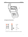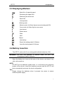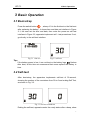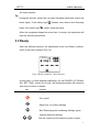
1
ATP-TL
User’s Manual
User’s Manual
ATP-TL Portable Luminescent ATP Detector
I
ATP-TL
User’s Manual
Notices and Restrictive covenants
Note: The design and manufacture of products are safe and
reliable,if use it properly(according to the text as shown
below) and comply with the following note fully, then it
will not cause harm to humans.
Note: This manual's user must be clear of this apparatus
and its possible harm attachment.
All operators
should be familiar with this chapter's
safety instructions and cautions before operating this
equipment.
If the operation of equipment not provided in detail in
accordance with the manufacturers instructions, then there
is the possible damage to equipment protection devices.
Legend:
Description: CAUTION / WARNING
Relate to the notes in the transporting, the using of
various types of solid power electronic equipment and the
II
ATP-TL
User’s Manual
using of swab Ultra snap required complying with.
Attentions are as follows:
——————Operating environment and electricity notes
Warning: Do not use equipment in the place having
or may having flammable and explosive gas.
Note: Do not place the equipment in extreme
temperatures, minimize the power load
——————Equipment operation
Note: Do not damage equipment, pick-and-place
carefully
——————Battery
Warning: Please use non-rechargeable alkaline
battery
Warning: The voltage of each battery should be
III
ATP-TL
User’s Manual
below 1.65V; Otherwise, it will cause lasting damage to the
quipment
Note: Please discard used batteries comply with
local regulations
——————Using and inserting Ultrasnap swab
Note: Before using the swab,please refer to the
details of the Ultrasnap's data and insert procedures.At
the same time, national and local environmental laws and
regulations should be followed.
Note: Do not insert Ultrasnap swab extrusion. In
addition to Ultrasnap swab, do not insert anything else.
Note: Prior to the insertion equipment,Ultrasnap
swab should be clean and dry .
——————Keyboard button
Note:Do not press the keyboard button on the
equipment's surface continuously.
——————RS232 interface
Warning: The computer equipment connected to
IV
ATP-TL
User’s Manual
RS232 interface on the top of the equipment
must meet
standards BSEN60950/IEC950.
——————Apparatus components:
Warning: The instrument does not have spare parts,
Demolition equipment components are not allowed.
V
ATP-TL
User’s Manual
Use Constraints
Equipment's design meets the requirements of popularity,
safety and EMC as following::
Popularity
► Low Voltage target 73/23/EEC
► EMC target 89/336/EEC
Safety
► BS EN 61010-1:200,IEC 61010-1:2001
► UL 61010B-1
► CAN/CSA C22.2 1010.1-92
EMS
► EN 55022:1998
► EN 61000-4-2:1995
► EN 61000-4-3:1995
► FCC Class A-Sub Part J
Statement
DESIGN OF THE EQUIPMENT CONFORM AND COMPLY WITH THE
REQUIREMENTS OF LOW VOLTAGE TARGET 73/23/EEC SECTION 11, AND
IN LINE WITH THE REGULATION THAT THE DESIGN OF ELECTRONIC
PRODUCTS NEED TO WORK UNDER THE SPECIFIED VOLTAGE AS WELL AS
THE BASIC REQUIREMENTS OF BS EN 61010-1:2001.
VI
ATP-TL
Contents
CONTENTS
1
2
3
INTRODUCTION ..............................................................................1
1.1
FEATURES OF ATP-TL ..............................................................................................................1
1.2
PERFORMANCE .........................................................................................................................1
1.3
APPENDICES AND SUPPLIES ......................................................................................................2
1.4
OPERATING PRINCIPLES ............................................................................................................2
PREPARATION..................................................................................4
2.1
STRUCTURE ..............................................................................................................................4
2.2
KEYBOARD FUNCTIONS ............................................................................................................5
2.3
DISPLAYING MARKERS .............................................................................................................6
2.4
BATTERY INSERTION .................................................................................................................6
BASIC OPERATION .........................................................................7
3.1
BOOT-STRAP .............................................................................................................................7
3.2
SELF-TEST ................................................................................................................................7
3.3
READY ......................................................................................................................................8
3.4
TURN OFF .................................................................................................................................9
3.5
LOW-POWER MODE ..................................................................................................................9
3.6
TIPS FOR LOW-POWER MODE .....................................................................................................9
4
CLOCK CONFIGURATIOIN ........................................................11
5
SET PROG NUM, GROUP NUM, AND THRESHOLD ..............12
6
DETECTION AND RESULT ..........................................................13
6.1
DETECTION .............................................................................................................................13
6.2
VIEW THE RESULTS .................................................................................................................14
6.3
DELETE THE RESULT ...............................................................................................................14
7
RESULT JUDGMENT.....................................................................15
8
SOFTWARE OF THE PC................................................................16
8.1
SOFTWARE INSTALLATION .......................................................................................................16
8.2
DATA TRANSMISSION ..............................................................................................................16
8.3
DATA FILE ...............................................................................................................................17
VII
ATP-TL
9
Contents
WARRANTY.....................................................................................18
10 MAINTENANCE..............................................................................19
11 TROUBLE SHOOTING ..................................................................20
VIII
ATP-TL
1 Introduction
1 Introduction
The ATP-TL portable luminescent ATP detector is applied in Sanitation
Supervision, in order to measure up the HACCP and GMP. The device
consists of two main parts. They are the Ultrasnap swab and the portable
examiner.
This manual introduces the use of the ATP-TL, and the maintenance and
trouble-shooting of the device.
For detailed introduction of Ultrasnap swabs, please refer to the
Ultralsnap user manual. If encountered with any technical problem,
please contact the manufacturer.
1.1 Features
The main specifications of this portable luminescent ATP detector:
z
Quantitative result: detecting limit 4*10-15 mol ATP(2000 bacteria)
z
Real-time detection: 1000 sampling hits/s,15 s for an assay
z
Small size: weight 210g
z
Ultra-low power:>200h working with 2 dry cells(1.5V)
z
Automatic: friendly user interface
z
Intelligent and network control: data transmitted to PC for
intelligent analysis and judgement
z
General use: fit for different ATP reagents
1.2 Performance
z
Testing time
15s
z
Detecting range
1-9999 RLUs
z
Detecting limit
4*10-15 mol ATP(2000 bacteria)
z
Repeatability
≤15
z
Correlation coefficient:
≥0.995
z
Detecting error
±5% or ±5 RLUs
1
ATP-TL
1 Introduction
z
Group limit
100 groups
z
Memory
1000 items
z
Operating temperature
5℃-40℃
z
Operating relative humidity
20%-80%
z
Preserving temperature
-10℃-40℃
z
Preserving relative humidity
20%-95%
1.3 Appendices and Supplies
Please contact the local distributor about appendices and supplies.
1.4 Operating principles
The Ultrasnap swab utilizes the biochemiluminescence technology. By
using this technology, the invisible ATP concentration (represent ATP
content in the testing swab) could be transferred into optical output which
is visible, see Fig.1.1.
Fig.1.1
The device could examine very low optical output, and display the
quantitative and qualitative results.
The quantitative result is an integer between 1-9999, in Relative Light
Units(RLUs). RUL is not a real optical unit (ex. lux), but it provides a way
to examine the total amount of optic outputs through ATP
biochemiluminescence detection. 1RUL stands for 1fmol ATP.
The quantitative results could provide qualitative results by comparison
2
ATP-TL
with user input program, as Pass
1 Introduction
, Alert
and Reject
.
The device is of high sensitivity, so please use it with caution.
3
ATP-TL
2 Preparation
2 Preparation
NOTE: Do please read the NOTICES at the very beginning of this manual.
2.1 Structure
The elevation of the ATP-TL is shown in Fig.2.1.
Fig.2.1
1 Cover
○
2 LED Screen
○
3 Keyboard
○
4 Buckle
○
5 Label
○
6 Battery Box
○
7 RS232 Socket
○
8 Sample Socket
○
4
ATP-TL
2 Preparation
Fig.2.2
2.2 Keyboard Functions
POWER
TIME
SETUP
UP、DOWN
Enter
The function of every single key will be described in later chapters.
5
ATP-TL
2 Preparation
2.3 Displaying Markers
PROG
Serial No. of inspecting spot
Examining the upper limit
Examining the lower limit
#
Result No.
/
List seperator
Working mark
Memory mark, its flicker figures memories beyond 90%
Cover mark, its flicker figures cover open
Insert arrow
Exsert arrow
Pass
Alert
Reject
Low battery
Exsert the testing swab if it flickers
Insert the testing swab if it flickers
2.4 Battery insertion
The ATP-TL works with 2 non-rechargeable alkaline batteries(1.5V).
WARNING: DO NOT use batteries of different kinds. DO NOT use
rechargeable alkaline batteries.
Open the battery box cover at the back of the device, and insert 2 dry
cells, with anode up.
NOTE:
DO NOT put the batteries upside down, or it will destroy the electronic
system of the device. Insert the batteries correctly and the ATP-TL will
boot automatically and enter the clock configuration.
Tips:
Please change the batteries when it prompts low power to assure
sufficient power supply.
6
ATP-TL
3 Basic Operation
3 Basic Operation
3.1 Boot-strap
Press the switch button
, a beep. If it is the first boot or the first boot
after replacing the battery , it shows time and date set interface in Figure
3-1, the user set the time and date, then enter the power-on self test
interface in Figure 3-2, apparatus implement self – test procedures. If not,
go directly to the self-test interface.
Fig.3.1 time set
Fig.3.2 self-test
Tips:
If the battery power is low, it can not boot or the battery logo
flashes
after boot, at this time we recommend that users replace the battery in
time.
3.2 Self-test
After boot-strap, the apparatus implements self-test of 30-second,
showing the number of the countdown from 30 to 0 and ending Self Test,
as shown in Fig. 3.3.
Fig.3.3 Self-test countdown
Ending the self-test, apparatus enter the ready status after a beep, show
7
ATP-TL
3 Basic Operation
the main interface.
Tip:
During the self-test, please do not insert Ultrasnap swab and ensure the
hatch tightly. If the taking logo
swab; If the hatch logo
flashes, then remove the Ultrasnap
linkes, close the hatch.
When the equipment keeps free more than 1 minutes, the equipment will
start the self-test procedures.
3.3 Ready
After the Self-test finished, the equipments enter the Ready condition,
which is the main interface (Fig.3.6).
PROG
Fig.3.6 Ready condition(Main Interface)
At this point, it needs keyboard operation, set up POWER, UP, DOWN,
OK, SET, TIME, a total of six keys, the following sections will introduce
each key's function in details:
key
function
Turn on/off
Show time, to confirm settings
Start Detecting point numbering settings, group
settings and time settings;
See the results; set the detection point number,
8
ATP-TL
3 Basic Operation
group number and time
Start testing; confirm detection, group number and
time
3.4 Turn off
Press turn on/off key
, turn off after a beef.
Tip:
In order to avoid Shut down accidents, during the process of sample
testing, all the keyboard keys will be locked in the status, when this
measurement ends, the lock status will be removed.
3.5 Low-power Mode
If the equipment is switched on, apparatus permit a maximum standby
time of 10 minutes, when the standby time is more than 10 minutes,
apparatus will automatically enter the energy-saving status with a beep.
Please press on / off button to restore.
3.6 Tips for low-power mode
Battery logo
indicates battery status:
Battery logo
Battery status
not visible
Full
Visible
Charging
Flashing
Low battery, replace it immediately
Visible with “√”
Fully charged
When the battery is low, the battery logo flickers, we recommend that
9
ATP-TL
3 Basic Operation
users charge the battery right away.
Tip:
If out of battery, the apparatus will not boot.
Because of high temperature can reduce the battery life, please place the
apparatus in the condition cool and dry.
10
ATP-TL
4 Clock Configuration
4 Clock Configuratioin
At the first run or after replacing the batteries, it will demand you to
configure time and date. The time-data configuration interface is shown in
Fig.4.1.
Fig.4.1
The time&date configuration goes in a repeating order of Hour, Minute,
Month, Date and Year. Respectively, press
flashing number and press
to modify the
to enter.
Tip:
If neither the
nor
is pressed, pressing
will cancel the
previous configuration. The default parameters will be displayed on the
screen.
After the time&data configuration, it enters self-testing.
When finished part of the configuration, pressing
will save your time
and data configuration. The time and data setup ends with several
defaulted.
11
ATP-TL
5 Set PROG num, Group num and Thresholds
5 Set PROG Num, Group Num, and
Threshold
When the ATP-TL is ready for detection, press
program number (figure 5.1). Press
program number. Press
and
and you may set
to change the value of
and continue to set upper threshold, lower
threshold and group number.
PROG
figure 5.1 set PROG num
The setting procedure is showed in following figure (figure 5.2).
Figure 5.2 setting procedure
12
ATP-TL
6 Detection and Result
6 Detection and Result
Tips: Before detection, read the user’s manual of Ultrasnap.
6.1 Detection
After self-detection, the ATP-TL is ready to work. The LCD displays as follows
(figure 6.1).
PROG
Figure 6.1 standby
It shows the PROG number, negative and positive threshold, and serial
number of the result.
Note: The memory of instrument could stores 1000 results. When over more
900 results are restored, the mark of
is shining.
Operation steps are as follows(figure 6.2).
Prepare the Ultrasnap swap.
Make sure the exterior surface of Ultrasnap clean and dry.
Open the lid, put the Ultrasnap into the instrument and close the lid.
Press
, and it begins to countdown 15 seconds.
PROG
Figure 6.2 detection countdow
Tips: Keep the instrument vertical and stable when it is working.
Result is displaying after countdown (figure 6.3).
13
ATP-TL
6 Detection and Result
PROG
Figure 6.3 detection result
Warning: Make sure the exterior surface of ultrasnap is clean and dry before
detection. Do not insert any other things except the ultrasnap.
6.2 View the results
Press
and
, you may view the detection results stored in the
instrument (figure 6.4).
PROG
PROG
Figure 6.4 view the results
6.3 Delete the result
After viewing the result, you can delete all the results stored in the instrument.
The operation steps are showed in following figures (figure 6.5).
Tips: When pressed
, the
and
delete all the records. Otherwise press
appear on the LCD. Press
, and
and quit.
Warning: Data on the ATP-TL can not be recovery once it was deleted.
PROG
Figure 6.5 delete the results
14
ATP-TL
7 Result Judgment
7 Result judgment
The ATP-TL has 100 programs (PROG 0~99), and each program has a couple
of upper and lower thresholds. The ATP-TL comprises the detection results
with the couple of thresholds automatically and draws a conclusion whether
the result is pass, warning or error (figure 7.1).
PROG
pass
PROG
warning
Figure 7.1 result judgment
PROG
error
The judgment basis are showed in following chart.
Detection result
result ≤ lower threshold
lower threshold < result≤upper threshold
result > upper threshold
Judgment
pass
warning
error
15
ATP-TL
8 Software of the PC
8 Software of the PC
8.1 Software installation
Put the CD into CD-combo, run the installation file and install the software
according to the installation prompt.
Tips : This software is working based on ‘.NET Framework’. You could
download the newest version of ‘.NET Framework’ from Microsoft official
website and install, or you could install the ‘.NET Framework 2.0’ embed in this
software (figure 8.1).
Without the ‘.NET Framework’, our software does not work.
Figure 8.1 install the ‘.NET Framework 2.0’
Finishing the installation, you can run the ATP Import program.
Data Transmission
Connect the ATP-TL and PC with the communication line provided by the
company (figure 8.3).
RS232 interface
one end of communication line connect with ATP-TL,
the other end connect with COM port of PC.
Figure 8.3 connection
Run ATP Import, select the correct port and file path. Press
, startup the
ATP-TL. It will display PC if connection is successful (figure 8.4).
16
ATP-TL
8 Software of the PC
Figure 8.4
Press Import, data transmission ready.
Choose Y, start transmission. Choose N, stop transmission
If you want to terminate the transmission, press cancel
After transmission, software will show you a suggestion. Choose Y to delete
the data on ATP, choose N to finish the transmission
When finishing the transmission, press ‘close com’, you can connect PC with
another ATP-TL and continue to transmit data on other ATP-TL.
Finally, press ‘exit’ and terminate all data transmissions.
Warning: Data on the ATP-TL can not be recovery once it was deleted. Make
sure you have the records before you delete.
8.2 Data file
Data of detection results are saved as excel files in PC.
eg:
SERIAL-NR
TEST-NR
RESULT
RLU
DOWN
UP
GROUP
PROG
TIME
DAY
DATE
827
0
error
230
100
200
0
0
1:0:3
Monday
2000.1.1
827
1
error
222
100
200
0
0
1:0:34
Monday
2000.1.1
827
2
error
214
100
200
0
0
1:0:64
Monday
2000.1.1
827
3
warning
197
100
200
0
0
1:1:23
Monday
2000.1.1
827
4
warning
168
100
200
0
0
1:3:72
Monday
2000.1.1
827
5
warning
153
100
200
0
0
1:5:0
Monday
2000.1.1
827
6
warning
135
100
200
0
0
1:6:18
Monday
2000.1.1
827
7
warning
117
100
200
0
0
1:7:67
Monday
2000.1.1
827
8
pass
92
100
200
0
0
1:9:18
Monday
2000.1.1
827
9
pass
88
100
200
0
0
1:9:48
Monday
2000.1.1
827
10
pass
88
100
200
0
0
1:9:71
Monday
2000.1.1
827
11
pass
80
100
200
0
0
1:16:8
Monday
2000.1.1
17
ATP-TL
9 Warranty
9 Warranty
z
z
The ATP-TL is warranted for a period of one year, from date of
shipment from the company, to be free from defects in material and
workmanship.
z
The above warranty is not applicable to defective devices with
incorrect use, abnormal operation conditions, improper application,
and unauthorized maintenance or alteration.
After-sell services please call 1-416-558-1088.
18
ATP-TL
10 Maintenance
10 Maintenance
Clean the instrument with dry cloth.
Warning: Do not wipe the instrument with wet cloth. Do not wash the
instrument with water.
Tips: Do not clean the instrument with solvent or cleaning agent, otherwise, the
plastics shell may be destroyed.
Replace the battery
Replace the battery for better results when the
mark appears.
Tips: The waste batteries should be treated according to local laws.
New batteries and old batteries can not be used in series.
19
ATP-TL
11 Trouble Shooting
11 Trouble Shooting
Check the visible cracks if there appears any problem. Do not disassemble the
instrument without the permission of the company.
The following aspects are possible reasons for the problems.
Problems
Possible Reasons
It does not startup when you press
Electric power of battery is not enough.
Wrong placement of the battery.
Instrument or keyboard is damaged.
Instrument is working now.
System halted: replace the battery after 10 sec.
Instrument or keyboard is damaged.
Electric power of battery is not enough.
Loosing of the battery.
Instrument is damaged or intensively shocked.
It dose not work for 10 minutes.
Electric power of battery is not enough.
Instrument or LCD is damaged.
Instrument works in an unsuitable environment,
such as too hot and too cold.
The display window is broken or depressed.
Instrument or LCD is damaged.
Instrument is detecting the fluorescence.
Some keys are available when specific
programs are chose.
Instrument or keyboard is damaged.
It needs self-detecting: take out the swab and
close the lid.
Swaps used error.
Swaps are overdue.
Instrument is damaged.
Connection between the instrument and PC is
error.
Use wrong software.
PC software is wrongly installed.
Connecting wire or interface is broken.
Instrument is damaged.
It does not shutdown when you press
Extra-ordinary shutdown
LCD does not display any thing
Abnormal display of LCD
Keyboard does not work
The
mark
is shining
Results are always 0 or error.
RS232 does not work
20
ATP-TL
12 Appendix : ultrasnap operation
12 Appendix: ultrasnap operation
Ultrasnap ATP swab is an integrated device using a unique liquid-stable
reagent and Snap-Valve technology to deliver unbeatable accuracy and
reproducibility. Simply swab an area, snap, squeeze and read the results with
the ATP-TL in just 15 seconds. Ultrasnap swab and the ATP-TL puts the most
accurate, reliable and affordable ATP-monitoring system in the palm of your
hand.
1
2
3
5
4
6
7
1. Swab sample point. 10cm x 10cm square.
21
ATP-TL
12 Appendix : ultrasnap operation
2. Place swab back in swab tube.
3. Holding the swab tube firmly, use the thumb and forefinger to break the
Snap Valve by bending the bulb forward and backwards.
4. Squeeze Snap Bulb twice, expelling all liquid down swab shaft. Bathe
swab bud for 5 seconds.
5. Place Ultrasnap swab in ATP-TL.
6. Close lid of ATP-TL.
7. Initiate 15 second reading by pressing 'OK'. Reading will be displayed
with threshold levels and sign indicating Pass, warning or error.
22