1
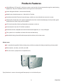
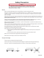
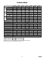
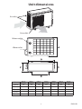
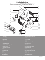
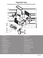
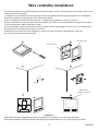
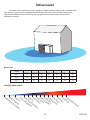
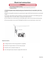
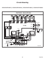
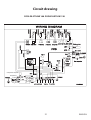
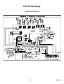
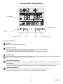
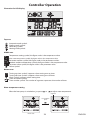
Contents
Important Instructions..... .......................................................................... 2
Products Features ........................................................................................ 3
Safety Precautions ....................................................................................... 4
Technical Data ............................................................................................... 5
Unit Dimensions ........................................................................................... 6
Exploded View ............................................................................................... 7
Tianium Heat Exchanger ..........................................................................13
Installation..................................................................................................... 14
Wire control installation ...........................................................................17
Noise level .....................................................................................................18
Electric connection .................................................................................... 19
Circuit drawing ............................................................................................20
Controller Operation ................................................................................ 23
Maintenance & Troubleshoting ............................................................ 34
Limited Warranty ........................................................................................ 36
1
ENGLISH
!
Important Instructions
!
These installation instructions are an integral part of the product and must be given to the installer and kept
by the user.
The warnings and indications contained in the present handbook must be carefully read and understood as
they provide important information relative to handling and operating safety. This handbook must therefore
always be kept available for later consultation.
Installation must be carried out in compliance with valid regulations and the manufacture's instructions by a
qualified professional.
An installation error could result in physical injury to persons or animals as well as mechanical damage for
which the manufacturer may under no circumstances be held responsible.
After having unpacked the heat pump, the content should be checked for possible damage.
Before connecting the heat pump, ensure that the data provided by Poolstar is compatible with the true
installation conditions and does not exceed the maximum authorized limits for the product in question.
In the case of a fault and/or operating error on the heat pump, the electrical power supply must be isolated
and no attempt should be made to repair the fault.
Repair work may only be carried out by an authorized technical assistance service using original spare parts
only. Non-respect of the aforementioned clauses may have a negative influence on the operating safety of
the heat pump.
To guarantee the efficiency and correct operation of the heat pump, it is important to ensure it is regularly
maintained in compliance with the instructions provided by Poolstar.
In the case where a heat pump is sold or transferred to another user, always ensure that all technical
documentation is sent with the equipment to be used by the new user or installer.
This heat pump may only be used for the purpose for which it was designed: to heat a swimming pool; all
other uses must be considered inappropriate, incorrect or even dangerous.
All contractual or extra-contractual responsibilities of Poolstar will be considered nil and void for any
damage caused by installation or operating errors, or due to non-respect of the instructions provided by
Poolstar or valid installation standards for the equipment object of the present document.
2
ENGLISH
Products Features
High efficiency, COP up to 5.5, which can save as much as 80% of cost compared to regular water heating
equipment. Easy for installation and low running cost for maintenance.
Green refrigerant R410A---environment-friendly
Word-known brand compressor---Mitsubishi or Toshiba
Durable and reliable Titanium heat exchanger, which can resist chloride ion corrosion in water.
Good quality Evaporator with superior hydrophilic alum foil, inbuilt threaded pipe, which provides good
performance in water skiing and anti-defrost.
LCD wired controller, allowing all operation parameters to be set.
Circuit board in line with CE & ROHS standards.
Automatic control, adopted auto control thermostatic apparatus, it is very intelligent.
The system has an excellent insulation for water and electricity.
Monoblock design, beautiful and compact plastic cabinet, with winter cover.
Winter cover
It is specially designed for Poolstar heat pump, which can protect the heat pump during winter period.
EVA materials, anti-dust, anti-UVA, anti-UVB.
This dust cover is proposed as an optional extra.
Enjoy Poolstar air source swimming pool heat pump is a wise choice for you.
3
ENGLISH
Safety Precaution
! NOTE
!
It is required to read the safety precautions in details before operation. The precautions listed below are all-important for safety. Please
follow the instructions strictly.
General
Make sure that the fixed ground wire in the building is securely connected to earth.
Wiring tasks should be carried out by qualified electricians only, In addition, they should check the safety
conditions of power utilization, for example, check if the cable capacity is adequate, and check the power
cable is damaged.
Horne users must not install , repair or relocate the unit. Improper treatment might lead to the accidents e.g.
persona! injury caused by fire, electrical shock or unit's falling-off, and water leakage in the machine. Please
contact professionals for repair.
The unit shall not be installed at a spot with potential hazard of leakage of inflammable gas. In case the
leaked gas is congregated around the machine, there might be the risk of explosion.
Make sure that the foundation of installation is stable .If the foundation is unstable, the outdoor unit may
drop and cause a casualty.
Make sure that the electric leakage protection switch is fixed . If no electric leakage protection switch is fixed
at the beginning of the electric supply, it may cause electric shocks or fires .
If any abnormity occurs in the unit (such as burned smell in side the unit), cut off the power supply
immediately, and contact professionals for repair.
Please follow the instruction below when cleaning the unit :
a. Before cleaning, eut off the electric supply of the unit firstly to avoid injuries caused by fan in
operation.
b. Do not rinse the unit by water because the rinsed unit may cause electric shock.
Make sure to cut off the electric supply before maintaining the unit.
Please do not insert fingers or sticks into air outlet or air inlet.
Transport and storage
The unit must be transported and stored vertically.
The unit must always be stored and transported upright on a pallet and in the original packag ing.
If the unit is stored or transported laying down, wait atleast 12 hours before switching on.
4
ENGLISH
Heating Capacity(W)
POOLEX
JETLINE 35
3550
POOLEX
JETLINE 48
4880
POOLEX
JETLINE65
6810
POOLEX
JETLINE 85
8530
POOLEX
JETLINE 100
10120
POOLEX
JETLINE120
12050
POOLEX
JETLINE 150
15020
Heating Capacity(BTU)
12106
16641
23222
29087
34509
41091
51218
Heating Input(W)
615
873
1250
1394
1719
2060
2650
Normal Current(A)
2.81
4.00
5.72
6.38
8.71
9.95
12.80
COP
5.77
5.59
5.45
6.12
5.89
5.85
5.67
Model
Air15/℃
Water13℃
[1]
Air24/℃
Water20℃
[2]
Air35/℃
Water27℃
[3]
Heating Capacity(W)
3905
5368
7490
9380
11090
13200
16520
Heating Capacity(BTU)
13316
18305
25541
31986
37817
45012
56333
Heating Input(W)
707
1004
1440
1600
1982
2370
3050
Normal Current(A)
3.24
4.59
6.59
7.32
10.02
10.85
13.96
COP
5.52
5.35
5.20
5.86
5.60
5.57
5.42
Cooling Capacity(W)
2450
3360
4905
5930
6820
9700
12400
Cooling Capacity(BTU)
8355
11458
16726
20221
23256
33077
42284
Cooling Input(W)
780
1060
1520
1870
2210
2990
Normal Current(A)
3.57
4.85
6.96
8.56
11.17
14.44
4070
19.66
EER
3.05
3.14
3.17
3.23
3.17
3.09
3.24
Max Current(A)
5.7
7.8
10
14
20
25
30
Power cable cross section(MM2)
3*1.5
3*2.5
3*2.5
3*2.5
3*2.5
3*3.5
3*3.5
1025x380x805
Power Supply
230V~50Hz
Setting temperature range
15℃~40℃
Running gemperature range
-5℃~43℃
Unit dimensions W×H×D(mm)
715x565x290
930x630x350
930x630x350
930x630x350
930x630x350
1025x380x805
Net Weight (KG)
39
47
50
57
60
85
98
Sound pressure level at 1m[4]
≤51
≤52
≤52
≤54
≤54
≤55
≤55
Sound pressure level at 4m[4]
≤38
≤40
≤40
≤42
≤42
≤44
≤44
Sound pressure level at 10m[4]
≤30
≤32
≤32
≤33
≤33
≤34
≤34
Water inlet/outlet dimension
1.5″
1.5″
1.5″
1.5″
PVC 50mm
1.5″
1.5″
1.5″
COMPRESSOR TYPE
MITSUBISHI
MITSUBISHI
TOSHIBA
TOSHIBA
TOSHIBA
TOSHIBA
TOSHIBA
Min.water flow(M3/h)
1.8
1.8
2.4
3.6
3.6
4.8
6
Refrigerant charged (KG)
0.6
0.75
1.05
1.75
1.65
2.4
3
Hydraulic connection
Water Heat Exchanger
Load loss(mCE)
3
Max.pool volume(M )[5]
Refrigerant
Titanium PVC Tank
1.5
1.6
1.6
1.68
1.68
1.71
1.75
0-23
20-33
30-45
40-65
R410A
55-80
75-95
90-120
Display
LCD
Mode
Heating/Cooling/AUTO
[1]Ambient air temperature 15℃(DB)/12℃ (WB), water temperature 13℃;
[2]Ambient air temperature 24℃(DB)/19℃ (WB), water temperature 20℃;
[3]Ambient air temperature 35℃(DB)/27℃ (WB), water temperature 27℃.
[4]Noise from 1m + from 5m + from 10m (in DBA) (As in the directives EN ISO 3741 & EN ISO 354...)
[5]Calculated for private inground swimming pool, with a bubles cover.
Unit dimensions
Air inlet
Air outlet
Water outlet
Water inlet
No.
A(mm)
B(mm)
C(mm)
D(mm)
E(mm)
POOLEX
JETLINE 35
POOLEX
JETLINE 48
POOLEX
JETLINE 65
POOLEX
JETLINE 85
POOLEX
JETLINE 100
POOLEX
JETLINE 120
POOLEX
JETLINE 150
565
630
630
630
630
805
805
715
850
850
850
850
1025
1025
290
300
300
300
300
365
365
313
313
313
313
313
380
380
500
530
530
530
530
640
640
6
ENGLISH
Exploded view
Construction of POOLEX JETLINE 35
1
2
14
15
3
16
4
5
6
7
8
17
18
24
25
26
19
20
27
28
21
22
23
1. Top cover
2. Internal clapboard
3. Back cover
4. Manometer
5. Four-way valve
6. Water pipe head
7. Inlet/outlet O-ring seal
8. Water switch
9. Titanium PVC tank
10. Bottom cover
11. Compressor
12. Wire control
13. Lifting handle
14. Evaporator
9
10
11
12
13
15. Electric control box cover
16. Motor frame
17. Fan motor
18. Fan
19. Electric control box
20. Front cover
21. High pressure switch
22. Low pressure switch
23. Needle valve
24. Fan motor capacitor
25. Compressor capacitor
26. Circuit board
27. Transformer
28. Terminal blocks
7
ENGLISH
Exploded view
Construction of POOLEX JETLINE 48 and 65.
1
14
2
15
3
16
4
17
5
6
7
18
19
8
9
10
11
12
13
23
24
25
26
20
27
21
22
1. Top cover
2. Internal clapboard
3. Back cover
4. Manometer
5. Four-way valve
6. Water pipe head
7. Inlet/outlet O-ring seal
8. Water switch
9. Titanium PVC tank
10. Bottom cover
11. Compressor
12. Wire control
13. Lifting handle
14. Evaporator
15. Motor frame
16. Fan motor
17. Fan
18. Electric control box
19. Front cover
20. High pressure switch
21. Low pressure switch
22. Needle valve
23. Fan motor capacitor
24. Compressor capacitor
25. Circuit board
26. Transformer
27. Terminal blocks
8
ENGLISH
Exploded view
Construction of POOLEX JETLINE 85
1
2
14
15
16
17
3
18
4
25
5
6
7
19
20
8
9
10
11
12
13
24
26
27
28
21
22
23
1. Top cover
2. Internal clapboard
3. Back cover
4. Manometer
5. Four-way valve
6. Water pipe head
7. Inlet/outlet O-ring seal
8. Water switch
9. Titanium PVC tank
10. Bottom cover
11. Compressor
12. Wire control
13. Lifting handle
14. Evaporator
15. Electric control box cover
16. Motor frame
17. Fan motor
18. Fan
19. Electric control box
20. Front cover
21. High pressure switch
22. Low pressure switch
23. Needle valve
24. Fan motor capacitor
25. Compressor capacitor
26. Circuit board
27. Transformer
28. Terminal blocks
9
ENGLISH
Exploded view
Construction of POOLEX JETLINE 100
1
2
14
15
16
17
3
18
25
19
20
4
5
6
7
8
9
10
11
12
13
24
26
27
28
29
21
22
23
1. Top cover
2. Internal clapboard
3. Back cover
4. Manometer
5. Four-way valve
6. Water pipe head
7. Inlet/outlet O-ring seal
8. Water switch
9. Titanium PVC tank
10. Bottom cover
11. Compressor
12. Wire control
13. Lifting handle
14. Evaporator
15. Electric control box cover
16. Motor frame
17. Fan motor
18. Fan
19. Electric control box
20. Front cover
21. High pressure switch
22. Low pressure switch
23. Needle valve
24. Fan motor capacitor
25. Compressor capacitor
26. AC contactor
27. Circuit board
28. Transformer
29. Terminal blocks
10
ENGLISH
Exploded view
Construction of POOLEX JETLINE 120
19. Moter frame
20. Fan motor
21. Fan
22. Electric control box cover
23. Electric control box
24. Front cover
25.Wire Mesh
26. wire control
27. Needle valve
28. Low pressure switch
29. High pressure switch
30. Run capacitor
31. Circuit board
32. Transformer
33. Fan motor capacitor
34. AC contactor
35. Terminal blocks
1. Top cover
2. Internal clapboard
3. Water switch
4. Water pipe head
5. Inlet/outlet O-ring seal
6. Back cover
7. Titanium PVC tank
8. Four-way valve
9. Right supporting frame
10. Right cover
11. Manometer
12. Bottom cover
13. Compressor
14. Gas/liquid separator
15. Top supporting frame
16. Left cover
17. Left supporting frame
18. Evaporator
11
ENGLISH
Exploded view
Construction of POOLEX JETLINE 150
1. Top cover
2. Internal clapboard
3. Water switch
4. Water pipe head
5. Inlet/outlet O-ring seal
6. Back cover
7. Titanium PVC tank
8. Four-way valve
9. Right supporting frame
10. Right cover
11. Manometer
12. Bottom cover
13. Compressor
14. Gas/liquid separator
15. Top supporting frame
16. Left cover
17. Left supporting frame
18. Evaporator
19. Moter frame
20. Fan motor
21. Fan
22. Electric control box cover
23. Electric control box
24. Front cover
25.Wire Mesh
26. wire control
27. Needle valve
28. Low pressure switch
29. High pressure switch
30. Run capacitor
31. Start capacitor
32. Circuit board
33. Soft starter
34. Transformer
35. Fan motor capacitor
36. AC contactor
37. Terminal blocks
12
ENGLISH
Titanium heat exchanger
Refrigerant inlet
Refrigerant outlet
Water out
Water in
Water switch
PVC inner-tube
PVC outcase
Water outlet
Titanium pipe
Water inlet
1.Standard connectors, reliable, easy installation;
2.Sensitive water flow switch, detect water flow precisely.
3.Double spirale titanium tubes in heat exchanger, high effeciency;
4.PVC inner-tube design, make better heat exchanging.
13
ENGLISH
Installation
! ATTENTION !
1.During installation, do not pick up the unit by the top panel, use the
base to lift the unit.
2.Installation must be carried out by professional.
Selection of installation site
1. installation must be simple and allow easy access for later work.
2. If the unit is to be installed on the floor, its undercarriage should be heightened, to avoid ingression of
accumulated water in rainy season. In snowy areas, it is important to prevent accumulated snow from
blocking up the air-out.The recommended height is 20cm to 30cm.
3. Drain ditch or other facilities should be arranged under the outdoor unit, to avoid the environment
influence because of water discharge.
4. To install the unit at balcon or top of building, the installation site must meet the allowable bearing
capacity of building structure, without affecting the structural safety.
5. Ensure the unit is well vetilated, direction of air exhaust is kept away from windows of neighboring
buildings, and the exhaust air cannot flow back. Moreover, adequate service clearance should be kept
around the unit.
6. The unit should not be installed at places accompanied with oil, Inflammable gas, corrosive components,
e.g. Sulfur compound, or high-frequency equipment.
7. The unit must be installed on reliable base or framework. Weight capacity of framework should be 3 times
of the body weight, and safeguard measures should be taken to avoid malfunction of fastenings.
8. The unit should not be installed at sites with typhoon/earthquake hazards. Midair installation should be
avoided as much as possible as machine falling down may result in severe accident.
9. Do not install the heat pump close to a road or path to avoid mud splashing on the unit.
10. Keep, wherever possible, the unit out of reach of children.
Installation in exceptional circumstances(unit:mm)
No obstacle in front of unit
Obstacle above the unit
14
ENGLISH
Installation
Valve 1\Valve 2\Valve 3 : Bypass valves.
Valve 4\Valve 5 :Setting valves*.
* Recommended to facilitate adjustments close to the machine.
Heat pump
Valve 1
Valve 5
Valve 3
Valve 2
Water out
Water in
Condensate drain
Pump
Filter
FROM SWIMMING POOL
TO SWIMMING POOL
15
ENGLISH
Installation diagram
SWIMMING
POOL
WATER OUT
WATER IN
DRAIN VALVE
CIRCULATION PUMP
FILTER
Installation diagram for combination
WATER OUT
WATER IN
DRAIN VALVE
SWIMMING
POOL
WATER OUT
WATER IN
DRAIN VALVE
CIRCULATION PUMP
FILTER
The filter connected with pipes should be cleaned regularly to make sure the water inside systems clean, and also
avoid other troubles of unit caused of dirty or blocked filter.
Winter anti-freezing instruction
1. The heat pump unit has auto antifreeze program. When the unit is working normally, there will not be freezing.
2. When the ambient temperature is minus, and the unit stops for over 3 hours, or the unit stops long term when
power off. the user is advised to drain all the water inside pipes through the valve which connected to water
outlet,to avoid frost crack.
3. If the unit is under off season, should cut off power and take the protection cover outside of unit when
necessary.
4. Before restart the unit which has drained out all the water inside, the user is advised to reinstall the unit and
adjust program. further more need complete check of the system.
16
ENGLISH
Wire controller installation
The wired controller is originally fixed on the maintenance door of the machine; please refer to below steps if you
want to install it on the wall:
1. Take down the controller from the machine. Please pay attention that the communication wire is connected
with The circuit board, separate them from where they match.
2. Use a screwdriver to open the clip as picture 1, separate the controller as 2 parts, as picture 2.
3. On the wall that you are going to install the controller, drill 2 holes at a level parallel to the sight line as picture
3. The hole distance is 60mm, diameter is 8mm.
4. Place the plastic screws of the enclosure into the hole, and use the tapping screw (ST4*16 D-1) enclosed to fix
the back cover of controller on the wall, as picture 4
5. Match the front and back covers perfectly, as picture 5, make sure that it is fixed firmly on the wall.
6. Connect the communication wire well.
1
2
The front cover
The back cover
SE
T
M
3
4
60m
m
Φ8
Outlet of the
communication wire
5
6
M
SET
! Attention !
Please don't use keen-edged things to hit the controller face and keys, or it may cause damage.
When the controller is fixed on the wall, don't pull the communication wire, or it may cause poor contact.
17
ENGLISH
Noise Level
To reduce noise interference to your neighbors, please install the heat pump in a position that
faces the least sound sensitive neighboring area. Below table shows the noise level of our pool
heat pump at different distance. But they are only guide values because they will be further
affected by obstacles.
10 m
4m
1m
Noise Level
Model
Noise level at 1m
dB(A)
Noise level at 4m
dB(A)
Noise level at 10m
dB(A)
POOLEX
JETLINE 35
POOLEX
JETLINE 48
POOLEX
JETLINE 65
POOLEX
JETLINE 85
POOLEX
POOLEX
POOLEX
JETLINE 100 JETLINE 120 JETLINE 150
51
52
52
54
54
55
55
38
40
40
42
42
44
44
30
32
32
33
33
34
34
SCALE OF NOISE LEVELS
30
dB
:w
40
hi
sp
dB
:r
ef
50
er
ed
55
dB
rig
:r
ain
er
at
or
co
nv
er
sa
tio
n
dB
60
:w
as
65
dB
hi
:N
or
ng
dB
m
:T
al
70
V
dB
75
dB
80
dB
85
dB
dB
95
dB
10
0d
13
B:
:v
:
:
:k
:a
in
hi
ut bark law
la
gt acu
-fi
n
x
on
in
um om
on
m
g
ob
ow
e
ile
er
:r
co
nv
ac
er
hi
sa
ne
ti
m
90
on
18
0d
B
14
0d
ra
c
in
B:
g
air
pl
an
et
ak
eo
ff
ENGLISH
Electrical connection
! ATTENTION !
a. This section is an indication only and must be checked and adapted when neces
sary according to installation conditions.
b. Electrical installation and service must be carried outunder the supervision of a
qualified electrician.
1. The electrical power supply to the heat pump must be protected with a fuse and isolator switch (not
provided) in compliance with standards and regulations valid in the country in which the system is to be
installed.
2. The unit is designed for connection to a general power supply with full earth and neutral or neutral earth
systems.
3. The power supply cable must be connected to a circuit-breaker with at least a 3mm breaking gap. Inco
ming supply must be 220~240V/1/50Hz, via a distribution board with fuses.
4. If an insulation test is to be carried out in the building, please make sure to disconnect the heat pump.
5. The communication wire must be STP(Shielded Twisted Pair), the size should not less than 0.5 m㎡
Isolar switch
Important remarks:
A voltage variation of ±10% during operation is acceptable.
The electrical supply conduits must be securely fastened.
The cable must be suitable for outdoor use.
Use a cable gland to pass the power supply cable into the unit.
19
ENGLISH
Circuit drawing
POOLEX JETLINE 35 | POOLEX JETLINE 48 | POOLEX JETLINE 65 | POOLEX JETLINE 85
WIRING DIAGRAM
AN2(TC)
AN3(TD)
AN4(TW)
Brown
1 2
HP
1 2
High pressure
switch
1 2
Orange
BP
Low pressure
switch
t
Water tank
temp.sensor
t
Discharge temp.
sensor
CN3
AC220V
COMM1 AN1(TV)
t
Coil temp.
sensor
t
Ambient temp.
sensor
1 2
LD11 LD12 LD21 LD22
LD31
LD32
CN1
AC12V
1 2 3
PCB
FAN
AC-N
OUT4
COM.(3)
COM.(3)
N1
Relay
N2
N.O.(4)
OUT1
OUT2
CN2
1 2 3
Relay
Water switch
Gray
Fan motor
WHT
YLW/GRN
BLU
MF
RED
ORG
Fan capacitor
N.O.(4)
OUT5
BLU
WHT
BLU
4-WAY VALVE
Compressor
MC
WHT
WHT
BLU
BLU
BLU WHT ORG BRN
RED
YLW/GRN
Compressor
capacitor
L
N
YLW/GRN
P1 P2 S1 S2
BLU
AC220-240V50Hz
To pump To controller
2 0
G02Q0090
ENGLISH
Circuit drawing
POOLEX JETLINE 100 POOLEX JETLINE 120
WIRING DIAGRAM
AN3(TD)
AN4(TW)
Brown
1 2
Orange
1 2
HP
High pressure
switch
BP
Low pressure
switch
t
AN2(TC)
Water tank
temp.sensor
CN3
COMM1 AN1(TV)
t
Discharge temp.
sensor
t
Coil temp.
sensor
t
Ambient temp.
sensor
1 2
LD11 LD12 LD21 LD22
AC220V
LD31
LD32
CN1
AC12V
1 2 3
PCB
FAN
AC-N
OUT4
COM.(3)
COM.(3)
N1
Relay
N.O.(4)
OUT1
OUT2
CN2
N2
1 2 3
Relay
Water switch
Gray
Fan motor
WHT
YLW/GRN
BLU
MF
RED
ORG
Fan capacitor
N.O.(4)
OUT5
BLU
WHT
BLU
4-WAY VALVE
Compressor capacitor
Compressor
YLW/GRN
RED
MC
BLU
WHT
WHT
BLU
BLU
A1
BLU
WHT
A2
BLU
BLU WHT ORG BRN
L
N
P1
P2
S1
YLW/GRN
S2
BRN
AC220-240V50Hz
To pump
2 1
To controller
G02Q0091
ENGLISH
Circuit drawing
POOLEX JETLINE 150
22
ENGLISH
Controller Operation
LCD display
Clock and timer
ON/OFF
Mode selection
Up
Down
Parameter setting
Illustration for the keys
ON/OFF
Press it to switch on or off heat pump.
MODE SELECTION
Press it to select the mode. The sequence is: automatic-cooling-heating-automatic.
During parameter setting, press it to adjust parameters;
During clock and timer setting, press it to choose the hour value or minute value.
UP AND DOWN
Press them to adjust the value of water temperature, clock, timer, parameters; During failure checking and
parameter checking, press any of them to exit checking.
SETTING AND CONFIRM
Long press it for more than 6 seconds, you can check and adjust the parameters. Press the UP/DOWN key to
exit operation.
When a failure occurs, press it for no more than 2 seconds, you can check the failure code. Press it again you
can check the other failure code if more than one occurs. Press the UP/DOWN key to exit checking.
CLOCK AND TIMER KEY
Press it to set clock and timer. Detailed operation will be described in following pages.
During parameter setting, press it to change the rolling direction of parameters.
23
ENGLISH
Controller Operation
Illustration for LCD Display
Top area
Automatic mode symbol.
Cooling mode symbol.
Defrosting symbol.
Heating mode symbol.
Middle area
Temperature setting symbol, the figure under is the temperature value.
Inlet water temperature symbol, the figure under is the temperature value.
Parameter number symbol, the figure under is the parameter number .
Outdoor ambient temperature symbol, the figure under is the temperature value.
Parameter value symbol, the figure under is the parameter value.
Failure symbol.
Bottom area
Turning on timer symbol. It appears when setting turn on timer.
Turning off timer symbol. It appears when setting turn off timer.
Clock symbol. It appears when setting time.
Timer circulation symbol.
Timer number symbol. The number of segments represents the number of timer.
Water temperature setting
When the heat pump is switched on, just press
or
to adjust water temperature.
Clignote
For example
press
Initial state
24
ENGLISH
Fonctionnement de la télécommande
Clock setting
Set the system time according to the local time as follows:
Step 1 :
Step 2 :
Step 3 :
Step 4 :
Step 5 :
Step 6 :
press
press
press
press
press
press
to start clock setting, the symbol flashes.
to select hour and the corresponding value flashes.
or
to adjust the hour value.
to select minute and the corresponding value flashes.
or
to adjust the value.
to confirm the value.
S te p 1
S te p 3
S te p 2
Flash
Flash
Press for once
Adjust the hour value
Press to select hour value
S te p 4
S te p 5
S te p 6
Flash
Press to turn to minute value
Flash
Adjust the minute value
25
Flash
Confirm the value and return
ENGLISH
Controller Operation
ON/OFF timer setting
With this function, the heat pump can turn on or turn off automatically at the set time.
ON/OFF timer setting as follows:
Step 1 :
Step 2 :
Step 3 :
Step 4 :
Step 5 :
Step 6 :
Step 7 :
press
press
press
press
press
press
press
twice to start ON time setting.
to select hour and the corresponding value flashes.
or
to adjust the hour value.
to select minute and the corresponding value flashes.
or
to adjust the minute value.
to confirm the value.
to return to normal display.
S tep 1
S tep 2
S tep 3
F lash
F lash
Press f or twice
Press to select hour v alue
A djust the hour v alue
S tep 5
S tep 4
F lash
Press to turn to minute value
F lash
F lash
A djust the minute value
S tep 7
S tep 6
C onfirm the value
N or mal d isplay
F lash
Press to return to normal display
26
ENGLISH
Controller Operation
How to set an OFF time point
OFF timer setting
Step 1 :
Step 2 :
Step 3 :
Step 4 :
Step 5 :
Step 6 :
Step 7 :
press
press
press
press
press
press
press
for 3 times to start OFF time setting.
to select hour and the corresponding value flashes.
or
to adjust the hour value.
to select minute and the corresponding value flashes.
or
to adjust the minute value.
to confirm the value.
to return to normal display.
S tep 2
S tep 1
S tep 3
F lash
Press to select hour v alue
Press f or 3 times
A djust the hour v alue
S tep5
S tep4
A djust the minute value
N or mal d isplay
S tep7
S tep 6
F lash
F lash
Press to turn to minute value
F lash
F lash
C onfirm the value, and turn to
nexe ON /OF F t imer setting
F lash
Press to return to normal display
27
ENGLISH
Controller Operation
Totally 3 ON/OFF timers can be set. And they can be applied to use for every day or only one day. In timer
setting status, the figure below NO represents the timer sequence. If it shows “--:---“ on bottom, it means timer invalid.
Below examples show how to set the heat pump to switch on at 9:10 and switch off at 12:30, and switch on again
at 14:10 and switch off at 17:30, and switch on again at 19:10 and switch off at 23:30.
The 1 st ON/OFF time setting:
S tep 1
S tep 2
S tep 3
F lash
Press f or twice
Press to select hour v alue
F lash
Press to turn to minute value
S tep 6
F lash
S tep 8
F lash
S tep 9
F lash
A djust the hour v alue
Press to select hour v alue
S tep 10
F lash
C onfirm the value and
turn to OF F t imer setting
A djust the minute value
S tep 7
F lash
Press to turn to minute value
S tep 11
F lash
A djust the minute value
Adjust the hour v alue
S tep 5
S tep 4
F lash
F lash
F lash
C onfirm the value and turn to
next ON /OF F t imer setting
28
ENGLISH
Controller Operation
The 2nd ON/OFF timer setting:
S tep 1
S tep 2
F lash
F lash
Press to select hour v alue
A djust the hour v alue
S tep 4
S tep 3
F lash
Press to turn to minute value
F lash
A djust the minute value
S tep 6
S tep 8
F lash
A djust the hour v alue
Press to select hour value
S tep 9
F lash
C onfirm the value and turn to
O F F t imer setting
S tep 7
F lash
F lash
Press to turn to minute value
S tep 10
F lash
A djust the minute value
S tep 5
F lash
F lash
C onfirm the value and turn to
next ON /OF F t imer setting
29
ENGLISH
Controller Operation
The 3rd ON/OFF timer setting:
S tep 1
S tep 2
F lash
F lash
Press to select hour v alue
A djust the hour v alue
S tep 4
S tep 3
F lash
Press to turn to minute value
S tep 5
F lash
A djust the minute value
S tep 6
S tep 8
F lash
A djust the hour v alue
Press to select hour v alue
S tep 9
F lash
Press to turn to minute value
S tep 10
F lash
A djust the minute value
C onfirm the value and
turn to OF F t imer setting
S tep 7
F lash
F lash
F lash
C onfirm the value and exit setting
30
ENGLISH
Controller Operation
Timer mode setting:
The default mode is timer recurrence. Please refer to following steps to set one-day timer:
S tep 1
I t will s how “ A U T O” on
the L C D display w hen
it is timer r ecurrence.
I nitial s tate
S tate of running
S tate of s tandby
L ong press(≥ 6 seconds)
S tep 2
S tep 3
S tep 4
F lash
V alue
Parameter N o.
Press to turn to parameter N o.1
S tep 5
R olling direction
Press to select the value
A djust the value
Flash
Press
or
C onfirm
S tate of s tandby
S tate of running
31
ENGLISH
Controller Operation
Timer cancelling:
To cancel the timer, please refer to the instruction for timer setting and set it to be “---:---“ via the M key.
Please check below example for cancelling timer.
S te p 1
S te p 2
S te p 3
F lash
Press M b utton
Press f or twice
Press M b utton
S te p 5
S te p 4
F lash
F lash
Press M b utton
F lash
Press again and again
32
ENGLISH
Failure code Checking
When a failure occurs, it will show failure symbol on the screen.Press
(≤2seconds) you can check
the failure code. You can press it again to check another failure code if more than one occurs.
Press
or
to exit.
Common failures and maintenance
Failure
P9
failure
failure
failure
failure
33
ENGLISH
Maintenance & Troubleshooting
Parameter checking and adjustment
The system parameters can be checked and adjusted via the controller. But they should not be changed
casually, especially by house owners.
! Warning !
This operation is reserved to facilitate future service and maintenance. All parameters should not be changed casually, especially by
house owners!
How to check and adjust parameters:
Step 1 : long press
(≥6 seconds) to enter parameter checking mode.
Step 2 : short press
again and again to choose parameter that needs adjusting. If press
tion will be converted(+ to - or - to +)
Step 3 : press
to start parameter setting and the parameter flashes.
Step 4 : press
or
to adjust the value.
Step 5 : press
to confirm the value.
Step 6 : press
or
to return to normal display.
S tep 2
S tep 1
S tep 4 F lash
A djust the value
S tep 3
F lash
V alue
Parameter N o.
L ong press(≥ 6 seconds)
, the rolling direc
Press again and again R olling direction Press to start parameter setting
S tep 5
C onfirm
34
S tep 6
R eturn
ENGLISH
Maintenance & Troubleshooting
Parameter number and description are listed in the following table.
Remark : the machine off code
1:
2:
3:
4:
5:
6:
7:
8 : Exhaust air temp is too high, then stop the
machine.
9 : Low-pressure switch cutting
10 : High-pressure switch cutting
11 : Water-temperature resistance's breakdown
12 : Pipe-temperature resistance's breakdown
13 : Ambient temperature resistance's
breakdown
Power off
meet set temperature
Water-switch breakdown
Antifreeze finishing. then stop the machine
Defrosting preparation
Defrosting off
Mode change
25
40
45
40
45
35
20
5
30
25
20
5
50
30
10
10
15
15
0
35
The manometer instruction
0
50
The manometer is a ki nd of high pressure equipment, wh en the heat pump is on, the manometer pointer would point to the pressure
value of refrigerant, the max. value of protection is 42kg/Cm 2 • Wh en the he at pump is off, the pointer would point to the same value as
actual ambient temperature ( e.g. 28 'C) and related air pressure ( e.g.18kg/ cm 2 ).
Please check the manometer wh en y ou res tart the he at pump after not using for a long ti me, if it shows ambient
temperature valve is smaller than 2 'C, it me ans that refrigerant has leaked a lot, and y ou need to confirm with
professional engineer as soon as possible.
35
ENGLISH
0 826 102 852
0,15 € / min
www.poolex.fr
0 826 102 852
0,15 € / min