1
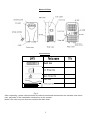
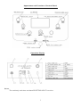
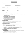
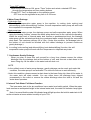
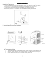
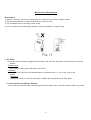
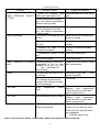
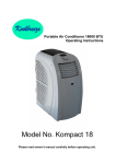
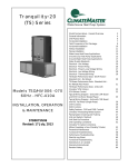
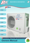
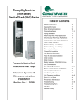
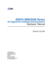
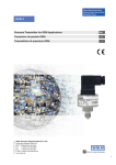
Koolbreeze
Portable Air-conditioner User’s Manual
For Model : CLIMATEMASTER
P-14000 HCJ
Table of Contents
1. Safety Awareness………………………………………………………………..1
2. Name of Parts……………………………….…………………………….……..2
3. Accessories………………………………………………..……………..……....2
4. Introduction to Control Panel………………………………………….. ………..3
5. Introduction to Operation………………………………………………..……….4
6. Installation Explanations…………………………………………………………7
7. Maintenance Explanations…………………………………………….………..9
8. Troubleshooting…………………………………………………………………..10
Before you use your portable air-conditioner, please read this instruction manual carefully so
that you get the best from the unit.
This instruction manual is used for guidance and does not form part of a contract. We reserve
the right to make technical changes without prior notice thus the machine illustrated may look
slightly different to that you have purchased.
Safety Awareness
1. Do not use the unit on a socket under repairs or not installed properly.
2. Do not use the unit:
A: Near to source of fire.
B: An area where oil is likely to splash.
C: An area exposed to direct sunlight.
D: An area where water is likely to splash.
E: Near a bath, a shower or a swimming pool.
3. Never insert your fingers, or rods into the air outlet. Take special care to warn children of these
dangers.
4. The appliance is not intended for use by young children or infirm persons without supervision.
5. Young children should be supervised to ensure that they do not play with the appliance.
6. Keep the unit upward while transporting and in storage to protect the compressor.
7. Before cleaning the air-conditioner, always turn off or disconnect the power supply.
8. When moving the air-conditioner, always turn off and disconnect the power supply, and move it
slowly.
9. Do not use an electric heater near the air outlet or within 15 mm of plastic parts.
10. To avoid the possibility of fire the air-conditioner should not be covered.
11. All the air-conditioner sockets must comply with the local electric safety requirements. If necessary,
please check it for the requirements.
Notes:
— If any parts become damaged, please contact the dealer or a designated repair shop;
In case of any damage, please turn off the unit, disconnect the power supply, and contact the dealer
or a designated repair shop;
Ensure the power cord shall is firmly grounded.
If the power cord is damaged, please turn off the unit and disconnect the power supply. It must be
replaced from the dealer or a designated repair shop.
Fuse on PCB: Type. 618, 3 . 1 5 A , 250VAC, Characteristics symbol: T, Breaking capacity symbol: L
1
Name of Parts
Accessories
Fig.2
After unpacking, please check whether the above-mentioned accessories are included, and check
their purposes in the installation introduction in this manual.
Notes: the cold-only unit does not contain the drain hose.
2
Appearance and Function of Control Panel
Operation Display
Notes:
The cold-only unit does not have ELECTRIC H E AT f un ct io n.
3
Operation Introduction
Before starting operations in this section:
1)
Find a place where there is power supply nearby.
2)
As shown in Fig.5 and Fig.5a, install the exhaust hose, and adjust the window position well.
3)
Insert the power cord into an grounded AC220~240V/50Hz socket;
4)
Press the ON/OFF button to turn on the air-conditioner.
4
Operation Introduction
Notice:
- Operation temperature range:
MAXIMUM HEATING
DB/WB (C)
MINIMUM HEATING
27/---
0/---
MAXIMUM COOLING
DB/WB (C)
MINIMUM COOLING
35/24
16/12
1. Before Using
Check whether the exhaust hose has been mounted properly.
Cautions for cooling and dehumidifying operations:
- When using functions on cooling and dehumidifying, keep an interval of at least 3 minutes
between each ON/OFF.
- Make sure the water pump is mounted correctly.
- That the power supply meets the requirements.
- The socket is for AC use.
- Do not share one socket with other appliances.
- Power supply is AC220--240V50Hz
2. Cooling operation
- Press the “Mode” button till the “Cool” icon appears.
- Press the “+" or “ - ” button to select a desired room temperature. ( 1 6 - 3 1 )
-
Press the “Fan Speed” button to select wind speed.
3. Dehumidifying operation
Press the “Mode” button till the “Dehumidify Indicator Lamp” blinks
- Set the selected temperature to current room temperature minus 2 .
( 1 6 -3 1 ) - Set the fan motor to LOW wind speed.
4. Heating operation (this function is not available for a cold- only Unit)
Press the “Mode” button till the “Heat” icon appears.
- Press the “+”o r “ - ” button to select a desired room temperature. ( 1 6 - 3 1 )
-
Press the “Fan Speed” button to select wind speed.
5. Timer operation
Timer ON setting:
- When the air-conditioner is OFF, press the “Timer” button and select a desired ON time
through the temperature and time setting buttons.
-
- “Preset ON Time” is displayed on the operation panel.
ON time can be regulated at any time in 0-24 hours.
5
Timer OFF setting
- When the air-conditioner ON, press “Timer” button and select a desired OFF time
through the temperature and time setting buttons.
- “Preset OFF Time” is displayed on the operation panel.
- OFF time can be regulated at any time in 0-24 hours.
6 Water Pump Drainage
- Cold-single type
There is self-evaporation water pump in the machine. In cooling (auto cooling) and
dehumidifying (auto dehumidifying) function, the self-evaporation water pump will work with
the compressor to evaporate any water.
- Heat pump type
a) There are two water pumps, the drainage pump and self-evaporation water pump. When
using the heating function, connect the water pump drain hose to the unit before operating.
When the water level of internal water tank reaches a predetermined level, the drainage
water pump will be activated and drain the condensed water outside through the connected
drain hose. The maximum delivery lift is 3.0m. (Under this condition, the drainage hole at
the bottom of unit should be blocked with the rubber blockage to prevent continuous
gravity drainage.)
b) In cooling (auto cooling) and dehumidifying (auto dehumidifying) function, the selfevaporation water pump will work with the compressor to evaporate any water.
7. Continuous Gravity Drainage
- When you plan to leave this unit unused for a long time, please remove the rubber
blockage from the drainage hole at the bottom of unit, and connect a drain hose to the
lower fixing clip. All the water in the water tank will drain out..
NOTE
- In the unlikely event of water pump damage, gravity drainage can be used, and under this
condition, the water pump is not activated. The unit will continue to work efficiently.
- Under this condition, please connect a drain hose to the lower fixing clip, then all the water in
the water tank will drain outside. You can either leave the drainage hose clipped
permanently to the outlet or remove the rubber blockage when the tank is full and the
water alarm operates.
8. Internal Tank Water Full Alarm Function
The inner water tank in the air-conditioner has a water level safety switch. When the water
level reaches an anticipated height in the internal water tank, the water full indicator lamp lights
up.
Note: it is normal that the water full indicator lamp will light up when the build-in water tank is full
as the unit works at room relative humidity of up to 70%.
6
Installation Explanations
1 Installation Explanations:
- The air-conditioner should be installed on a flat surface with space all around. Don’t block
the air outlet, The required distance around should be at least 30cm. (See Fig.7)
- Do not install in an excessively humid atmosphere such as a dry cleaners.
- Socket wiring should be in accordance with the local electric safety requirements.
3. Introduction to Exhaust Hose Installation
A) Temporary installation
1.
Twist both ends of the exhaust hose into the square fixing clip and the flat fixing clip.
2.
Insert the square fixing clip into openings at back of the air conditioner (see Fig.8).
3.
Put the other end of the exhaust hose to a nearby windowsill.
7
Window Slider Kit Installation
The installation can be “horizontal” or “vertical”,
As shown Fig.11 and Fig.11a, check the min. and max. size of the window.
8
Maintenance Explanations
Declaration:
1) Before cleaning, be sure to disconnect the unit from any electric supply outlet;
2) Do not use gasoline or other chemicals to clean the unit;
3) Do not wash the unit directly under a tap.
4) If the conditioner is damaged, please contact the dealer or repair shop.
1. Air Filter
- If the air filter becomes clogged with dust/dirt, the air filter should be cleaned once every two
weeks.
- Dismounting
Open the air inlet grille and take off air filter.
- Cleaning
Clean the air filter with neural detergent in lukewarm w a t e r a n d dry it up in the
shade.
Mounting
Putting the air filter into the inlet grille, replace the components as they were.
2. Clean the Air-conditioner Surface
First clean the surface with a neutral detergent and wet cloth, and then wipe it with a dry cloth.
9
Troubleshooting
Possible Causes
Troubles
Suggested Remedies
1. UNIT DOES NOT START
- Water full indicator lamp Dump the water out of the water
WHEN PRESSING ON/OFF blinks, and water tank is full.
tank.
Reset the temperature
BUTTON
- Room temperature is higher
than the setting temperature.
(Electric heating mode)
2. Not cool enough
Reset the temperature
- Room temperature is lower
than the setting temperature.
(Cooling mode)
- The doors or windows are not Make sure all the windows and
closed.
doors are closed.
- There are heat sources inside
Remove the
heat sources if
the room.
- Exhaust air hose is
connected or blocked.
3. Auto
mode
4. Noisy
possible
not Connect or clean the exhaust
air hose.
- Temperature setting is too Reset the temperature
high.
- Air inlet is blocked.
Clean the air inlet.
Power-Off in heating - Heating protection, when the
Restart the unit at when a lower
temperature at the air outlet room temperature.
exceeds 7 0 d e g r e e s , the
unit will power off
automatically.
- The ground is not level or not
flat enough
Place the unit on a flat,
ground if possible
It is normal.
level
- The sound comes from the
flowing of the refrigerant inside
the air conditioner
5. E0 Code
Room
temperature
sensor
Replace
room temperature
failed
sensor (the unit can also work
without replacement.)
6. E1 Code
Pipe temperature sensor failed
Replace
pipe
temperature
sensor (the unit can also work
without replacement.)
7. E2 Code
-RH70%.
- It is n o r m a l : t h e air is too
-Water pump failed.
humid, you can drain by hand. Restart the unit, and the failure
may disappear.
- Replace water pump.
Note: In the event of failure, contact the retailer from whom it was purchased.
10