1
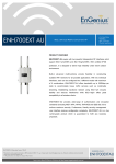
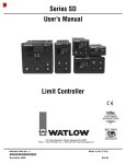
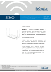
USER MANUAL
LSD2 – LEGEND STANDARD DEFINITION SET TOP BOX
www.legenddigital.com
www.legenddigital.com
v1.2
CONTENTS
Safety Instruction
Packing List
Front Panel
Rear Panel
Remote Controller
Installation Guide
EPG
Feature
Specification
3
4
5
5
6
7-11
12
12
13
2
SAFETY INSTRUCTIONS
Please read the following instruction carefully:
Do not overload power outlets, extension cords or integral convenience receptacles as this can
result in a risk of fire or electrical shock
Never allow liquids, spray or other materials to come into contact with the inside of the Set Top
Box (STB).
Unplug the STB from the power outlet before cleaning.
Use a soft cloth and a mild solution of washing-up liquid to clean the exterior of the STB.
Allow a clear space around the STB for sufficient ventilation.
Do not use the STB where it is exposed to direct sunlight or heat.
Never stack other electronic equipment on top of the STB.
Locate the STB in an indoor place to prevent exposing from lightening, rain and direct sunlight.
Do not use any attachments as these may cause hazards or damage the equipment.
Do not connect or modify the power cable attached to the STB.
Do not cover or place the STB on a unit that emits heat.
This symbol indicates
“dangerous voltage” inside
the product that present a
risk of electric shock or
personal injury.
This symbol indicates
important instructions
accompanying the
product.
TO REDUCE THE RISK OF ELECTRIC SHOCK
DO NOT REMOVE COVER (OR BACK)
NO USER SERVICEABLE PARTS INSIDE
REFER SERVICING TO QUALIFIED SERVICE PERSONNEL
3
PACKING LIST
ITEMS
Qty.
DIGITAL TERRESTRIAL RECEIVER
1
INSTRUCTION MANUAL
1
REMOTE CONTROL
1
AV CABLE
1
REMARK
Batteries inc
NOTE: Any changes will not be noticed in advance. Our company reserves the rights for the
explanation of the discrepancy.
4
FRONT PANEL
1
6
3
5
2 4
1. Card slot (NOT USED FOR AUSTRALIA)
2. EXIT: return to the program-watching status
3. MENU: Menu entry
4. OK: menu confirmation/ channel list
5. Remote receiver LED display window
7 8
10 9
6. Standby switch
7. Volume decrease/ left button
8. Channel increase/ up button
9. Volume increase/ right button
10. Channel decrease/ down button
REAR PANEL
1
2
3
4
5
6
1. Power switch
5. Video signal output terminal
2. Loop output terminal
6. Audio signal output terminal
3. Antenna signal input terminal
4. Serial data interface – only use for software upgrades
5
REMOTE CONTROLLER KEYS
Advise you operate each function of the STB using the button on the remote controller. Please
read this section to help advance your understanding of the function of the STB.
1.
: Standby control
2.
: mute the audio output
3. FAV : Non-Menu Mode: Select FAV list
4. TEXT : Non-Menu Mode: TEXT Teletext
5-6. ▲/▼ :
Menu Mode : Move cursor up/down
Non-Menu Mode: Program serial increase / decrease
7-8. -/+:
Menu Mode: Left or right button
Non-Menu mode: Volume decrease / increase
9. EXIT: Exit / Go back
10. MENU: Invoke or exit the menu operation
11. Numeric buttons 0-9: Input digits
12. SUB: Subtitles
13. TV/ RAD: Switch between TV and Radio
14. PAUSE: Non-Menu mode: Pause Picture
15. INFO: program’s Information
16. RECALL: Recall last channel
17. EPG: Electronic Program Guide
18. MULTI-FUNCTION Buttons: red (audio language)
green, yellow, blue (Electronic Program Guide)
19. OK: Non- Menu Mode: Channel List Menu Mode
Mode: Confirmation
PRECAUTIONS ABOUT BATTERIES
Improper use of batteries may cause corrosion or fluid leakage. Please observe the following
instructions for the safe use of batteries
1. Do not mix up the polarities of batteries
2. Never leave dead batteries in the remote control
3. Remove batteries from the remote controller if it is not going to be used for a certain time
4. Do not attempt to disassemble, short-circuit, heat, recharge or throw the batteries into a
fire.
5. Do not use new & old batteries together, or different types of batteries.
6. Wipe away any electrolyte fluid inside the remote controller, and insert new batteries
6
LEGEND INSTALLATION GUIDE:
LSD2 – LEGEND STANDARD DEFINITION SET TOP BOX
This document will guide you step by step on how to connect and set up your LSD2 set top box.
Users with experience in entertainment systems setup may not require this document as it is
intended for those with little or no prior knowledge on these units.
1) Place the unit in a suitable location near your TV. The unit should not be placed directly
on or under another electrical device (as this may cause interference) and should have
some room at the sides and top to allow the unit to remain cool.
2) Plug the unit’s power cord into your wall socket and turn on at the wall. On the back of
the unit, press IN the round POWER button.
Power is OFF
Power is ON
3) You should now see green lights on the front display of the unit (if you only have 1 green
LED but no information is displayed on the front LCD, your unit is in standby. Press the
power button on the FRONT and you will see the LCD activate and show green indicator
bars). If all is well you should see this:
7
4) You now must connect your aerial. You may have an inside aerial (rabbit ear type) or a
roof antenna with a wall plug. Using an appropriate cable, connect the aerial to the RF IN
connection on the rear of the unit (top middle) as below:
5) Now you must connect the AV cables (the red, white, and yellow cables that came with
your unit) to the rear of the unit. The cables are colour coded; simply connect them with
the colours matching.
8
Diagram above shows all connections in place for LSD2.
Read on for further instruction.
6) The other end of the AV cables will need to then be connected, in the same way, to the
AV-INPUT connectors on either your VCR or your TV. In order to record from your digital
box to videocassette, you will need to connect the unit direct to the VCR (set VCR to
appropriate AV channel as indicated on the connection you use, eg AV1, AV2…) and
then connect the VCR to the TV as per normal. Otherwise, connect the unit direct to the
TV (in this case, set the TV to appropriate AV channel as indicated on the connection
you use, eg AV1, AV2…).
7) If you have made the connections correctly, everything is turned on, and you are set to
the correct AV channels, you will now see this image on your TV screen:
9
8) Now you must SCAN in your channels. Make sure the batteries (supplied) are installed in
your REMOTE CONTROL unit. Point the remote at the digital box and press MENU.
Then use the up and down buttons on the remote to highlight SCAN at the bottom of the
menu, and press OK. You should see the following:
9) After checking that the SCAN TYPE is set on AUTO, and the BAND WIDTH is set to
7MHz (leave the Channel Number field BLANK), use the down button to highlight START
SCAN and then press OK. You will see the unit picking up channels as it scans, like this:
10
10) When the scan is completed, the detected channels will automatically be saved, and the
unit will exit from the menu.
*** IMPORTANT *** If your unit does not find any channels, then the aerial is not
connected properly or your reception is very poor. Your antenna may need to be
tested/adjusted, or you may require an inline “signal booster” to amplify the weak
signal in your area. Your local TV service technician can assist with these.
11) If everything has been done right, you have been TURNED ON with Legend Digital! You
may now enjoy the benefits of Digital Television, and can refer to your user manual for
further operating instructions.
11
EPG – Electronic Program Guide
To show information on programs currently playing press the EPG button.
Press the red key to show information on the current program and the green key to show what
program is on next.
Press the yellow key to read the particulars.
Press the blue key to show the weekly information.
FEATURES
Auto, manual and NIT convenient channel scan
Tremendous storage of channels
Six users defined Favorite modes (news, sports, cinema, MTV, economy and art)
EPG / Recall / Still
Subtitle instruction self-select
AV aspect selectivity self-control
Menu and channel locking function
Timer function
Factory reset (initialization) function
High Sensitive Tuner
LED display component
Automatic PAL / NTSC Detection
More particular text offering
Signal loop output terminal
Convenient software up-grade (pc to box; box to box)
Powerful edit abilities (rename, add, delete, sort) channels
12
1
SPECIFICATION
Tuner
Input Frequency
UHF 470 MHz ~ 862 MHz
VHF 174 MHz ~230 MHz
RF Input Level
-78dBm ~ -20dBm (75W)
RF Input connector
IEC type Female
RF Output connector
IEC type Male
Nominal input impedance
75 ohm
Channel selection system
Electronic tuning, PLL synthesizer
Step frequency
166.67KHz
Channel Decode
Demodulation
COFDM
Video
Profile Level
MPEG-II MP@ ML
Output System
NTSC / PAL
Output Terminal
RCA, TV Scart, VCR scart
Output Level
1Vp-p (75W) (RCA)
Audio
Audio Decoding
MPEG-II layer I & II
Freq response
20Hz ~ 20kHz
Output Level
Adjustable (600W unbalance)
Working condition
Power supply voltage
AC: 90~240V 50/60 Hz
Power consumption
About 15W
Temperature
0°C ~ 40°C
Humidity
10% ~ 90%
Size
300 X 210 X 64mm(L/W/H)
Weight
Approx. 2.4Kg
13