1
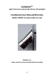
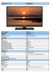
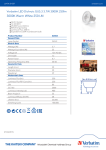
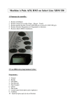
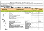
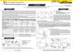
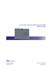
High Quality European based Manufacturers
NON MAINTAINED SELF-TESTING SPOT LIGHT
EMERGENCY LUMINAIRES WITH 1 WHITE POWER LED
TECHNICAL CHARACTERISTICS
OPERATION VOLTAGE
MAXIMUM POWER CONSUMPTION
BATTERY (Ni-MH)
BATTERY PROTECTION
INDICATIONS - CONTROLS
CHARGE TIME
MINIMUM DURATION
LIGHT SOURCE
EMERGENCY ILLUMINATION
DEGREES OF COVER PROTECTION
PRODUCED IN ACCORDANCE WITH
OPERATION TEMPERATURE RANGE
RELATIVE HUMIDITY
CONSTRUCTION MATERIAL
EXTERNAL DIAMENTION
WEIGHT
GUARANTEE
GR-290
GR-293
220-240V AC/50-60Hz
3W / 3.5VA
3.5W / 4 VA
3.1W / 3.6 VA
4.8V/1.2Ah
Discharge and over charge protection
Charge, lamp fault, battery fault, TEST button
24 hours
1.5 hour
3 hours
1 white power LED
200lm
250lm
140lm
IP 42
EN 60598-1, EN 60598-2-22, ΕΝ 55015, ΕΝ 61547, ΕΝ 61000-3-2, ΕΝ 61000-3-3
o
5 to 40 C
Up to 95%
Bayblend FR3010, clear polycarbonate
Ø125 x 65 mm
450gr.
3 years (1 year for the battery)
Thank you for purchasing this product of
Olympia Electronics. A European manufacturer.
GENERAL
This device is used in places where emergency
luminaires are needed. The luminaires GR-290,
GR-290/250 and GR-292 are suitable for
corridors lighting and the GR-291, GR-291/250
and GR-293 for open area lighting.
Each device must be permanently connected to
mains power supply.
In normal operation the battery is charging.
In case of a mains power supply failure the
device will light the illumination led
automatically in emergency mode. When the
mains power supply is restored the device
turns to normal operation.
INSTALLATION
To install the luminaire follow the installation
instructions οn page 2.
Battery charging
The battery charging is completely controlled. In
this case, is achieved the perfect battery
maintenance , as well as the elongation of its
duration. When the battery has completely
charged, it charges with a maintenance current.
Battery Cut-off
The device in this operation when the mains
power supply fails and battery has lost its
energy. During this operation the device enters
the idle state and battery consumption is
negligible, in order to be protected from deep
discharge.
Manual Test
This test can be done by pushing the test
Page 1 from 4
GR-291 GR-290/250 GR-291/250 GR-292
button. The light source and the emergency
circuit of the device is monitored. The manual
test can be conducted only if the main power
supply and the battery is connected. During this
test period all indication LEDs are OFF.
Automatic test
This test includes all the operations that provide
the manual test and is conducted automatically
every 15 days. In order to be performed, the
main power supply and the battery should be
connected.
Manual Autonomous Test
If the Test button is pressed for a period between
5 to 10 seconds (with the battery fully charged),
the device will enter in counting autonomy
condition. If the battery is not fully charged this
command is ignored.
The BATTERY FAULT LED blinks during the
measurement, indicating this process to the
user. This measurement duration is equal with
the nominal autonomous duration and at the end
of the process, if the measured duration was at
least the nominal autonomous duration, the
BATTERY FAULT LED is turned OFF, in the
other hand stays continuously ON indicating to
the user that the battery must be replaced.
Automatic Autonomous Test
The Automatic autonomous Test is conducted
and measures the device’s back up operation
and emergency duration. This test is conducted
automatically every six months. In order to be
performed, the main power supply and the
battery should be connected and fully charged. If
the battery is not fully charged, the test is
postponed until the battery is completely
923292000_09_007
charged. If during this test, the autonomy is less
than nominal then the battery fault led turned on
continuously and the battery must be replaced.
Back Up Operation
The autonomous duration of battery during
emergency mode is at least the one that is
stated in the list of the technical characteristics.
During emergency mode, a light source test is
also performed.
Resetting Errors
Push the Test button for >10 seconds, to delete
all the indicated LED errors. Then the device
enters regular operation mode.
Test switch
Pressing the test switch less than 5 seconds will
initiate a light source test (last for 3 secs).
Pressing the test switch between 5 to 10
seconds will initiate a manual battery duration
test. This test will not be started if the battery is
not fully charged (i.e. If the green LED is
flashing).
If the test switch is pressed for more than 10
seconds, the device will be reset (delete all
errors).
ΑΤΤΕΝΤΙΟΝ!!!
1. Operations for installation, maintainance or
testing must be done by authorized personel
only.
2. The device must be connected to the mains
power supply thru a fuse dependent by the total
amount of the line’s power load.
3. The replacement of the battery and the light
source must be done using parts of the same
type, by the manufacturer or by a competent
person.
4. In case of inactive use for a period greater
than 2 months, disconnect the battery by pulling
out the battery’s connector.
5. It is not allowed to discard batteries into
common trash bins, they must be
discarded only in battery recycling
points. Do not incinerate.
NOTE: LED= Light Emitting Diode
LABELING EXPLANATION:
X: Self contained
0: Non-maintained (*)
A: Including test device
*90: 1.5 hour duration
180: 3 hour duration
(*) Non-Maintained operation: The luminaire
lights its illumination source, only in power
supply’s failure.
Maintained operation: The luminaire lights its
illumination source, when it is powered by the
mains power supply or not.
INSTALLATION INSTRUCTIONS
2
3
N
3
L
1
Initial installation
1 Untighten the screw but do not remove it and pull up the reflector.
2 Place the battery’s connector to the corresponding connector on the P.C.B.
3 Use any round suplly cable with an external diameter of 4,5-8m (H05RN-F type 2x1mm² or
any other type, at least equal to it’s mechanical and electrical properties).
WARNING!! The cable must not be deformed in order to preserve the IP rating.
Use a cable grommet type PG9 (Not supplied in the package) and pass the cable. Tighten the
cable gland to form the seal. Detach the power terminal, connect the wires as shown in the
picture and attach the power terminal.
4 Refit the reflector (mind the correct orientation), tighten the screw securely and the luminaire
is ready for mounting.
NOTE!! After finishing the installation you must power the luminaire at least for 24 hours for
battery charging to perform the named autonomy.
To mount the device in a suspended ceiling follow the steps of the ‘’Mounting the lamp‘’ section.
For surface mounting (on wall or on ceiling) follow the steps of the ‘’Surface mounting‘’ section.
Page 2 from 4
923292000_09_007
Mounting the lamp in suspended ceiling.
Set up the lamp to the suspended ceiling as it is shown bellow (Required opening 110mm):
Step 1
Bend the springs, to get into the hole of the suspended ceiling, as you can see to the next figure.
Figure 1
Step 2
Push up the luminaire, as shown in figure 2.
Figure 2
Step 3
Continue to push upwards until the lamp locks.
Figure 3
If you want to pull off the device, put a flat blade
screwdriver, between the device and the ceiling.
Surface mounting. Install the luminaire according to following steps:
Step 1. Follow the step 1 of the installation instructions.
Step 2. Unfasten the retaining screw 4 and detach the part for suspended ceiling installation.
Step 3. Install the base with the included mounting parts 5. ATTENTION!! Especially for the GR-290,
GR-292 and GR-290/250 luminaire installation on the ceiling you must align the base with the
indications on the luminaire’s base 6.
Step 4. Follow the step 2,3 and 4 of the installation instructions.
4
5
6
Decorative Rims
Page 3 from 4
923292000_09_007
Status of LEDs
LEDs
Description of indication
CHARGE
: Battery charging,
: battery charged,
LAMP FAULT
: Operation check,
: lamp fault,
: normal operation
BATT. FAULT
: Autonomy test,
: battery fault,
: normal operation
Note
: Blinking,
: constantly on,
: disconnected battery or open
: off
Important notice for the installed luminaires in one area !!!
The installer must connect the battery’s connector first and then should power the luminaire.
The time between batteries connection must be, at least 1.5 minute.
With this variation, it is ensured that the non synchronized Automatic Autonomous Test for
two or more luminaires installed in one area, is not conducted in the same day.
Battery replacement.
It can be done only by a competent person and after the mains interruption.
1. Remove the luminaire from the suspended ceiling (figure 3).
2. Follow the step 1 of the installation instructions.
3. Disconnect the connector and remove the old battery.
4. Connect the new battery with the same type (step 2 of the installation instructions) and place it in
the position of the old one.
5. Replace the removed parts (step 1 and 4) and power the device.
GR-290, GR-292, GR-290/250
65
Corridor
lighting
125
LAMP BATT.
CHARGE
TEST
FAULT
98
ATTENTION!!!
During installation follow this light direction.
Lamp fault
indication LED
Battery
charge
indication
LED
Battery
fault
indication
LED
LAMP BATT.
CHARGE
TEST
FAULT
Figure 4
Test
button
GR-291, GR-293, GR-291/250
Open
area
lighting
Caution - Class 1M LED radiation
Do not view directly with bare eyes
Page 4 from 4
923292000_09_007