1
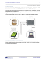
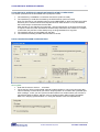
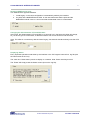
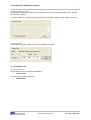
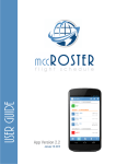
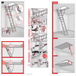
LN-200 IMU DATA INTERFACE/LOGGER
USER GUIDE
Av. De France 90
CH-1004 Lausanne
www.vnrsa.ch
Tel. +41 21 647 64 36
Fax. +41 21 647 64 61
[email protected]
LN-200 IMU DATA INTERFACE/LOGGER
2
F:\vnr\doc\Interface IMUGPS\User Manual.doc
SYSTEM OVERVIEW
The LN-200 IMU Data Interface/Logger provides an advanced interface between an Inertial
Measurement Unit Lutton LN-200 and a GPS Receiver with 1PPS and NMEA/ZDA output.
The LN-200 IMU Data Interface/Logger precisely synchronizes the incoming IMU data with GPS time
and sends them over the Ethernet port.
The high bandwidth of the communication ports easily handles up to 400Hz of IMU data that are
logged on customer-provided PC.
The precisely time-tagged data can be used for real-time or in post-mission GPS/INS integration.
LN-200 IMU
Data Interface/ Logger
INS LN-200
NME/ZDA output
1PPS
Ethernet
connexion
GPS RECEIVER
e.g. JAVAD
LEGACY GD
PC Portable
LN-200 IMU DATA INTERFACE/LOGGER SETUP
The LN-200 IMU Data Interface/Logger has automated setup, no user action is requested on the
interface side after power up or after the reset button has been pressed. (See next section for details
on automated start-up sequence).
© 2003 VNR Electronique SA
CH 1004 Lausanne
LN-200 IMU DATA INTERFACE/LOGGER
3
LN-200 IMU DATA INTERFACE/LOGGER AUTOMATED START-UP SEQUENCE:
This section presents how the automated start-up sequence works:
1. The Interface try to establish a connection with the PC (until it succeed).
2. The interface try to read time furnished by the GPS Receiver (until it succeed).
Note: For the start-up, the Interface need a correct NMEA/ZDA (or GPS Time with Javad GPS
Receiver) and 1 second interval PPS outputted from the GPS Receiver. If not, the Interface
will not be ready to receive data from the IMU.
After the start-up, the Interface only need the 1 second interval PPS. If the GPS receiver fails
to output correct PPS, then the Interface will time stamp data with a time based on it oscillator.
In the mode, the precision of time stamps may not be guaranteed for a long time
3. The Interface wait for incoming data from the IMU.
4. The Interface timestamp packets and send them to the PC.
DATA LOGGER PROGRAM CONFIGURATION:
Saving data:
• Enter the file name or click on ... to browse.
• The check box "Save incoming data" permits to select whether or not to save incoming data.
This functionality is useful when you want to acquire position in a location with a potential poor
GPS coverage. In fact you can synchronise the Interface in a location where you are sure to
get sufficient GPS coverage, and then move to another location without saving unneeded
data, but in keeping synchronisation or in using the Interface clock to extrapolate time.
© 2003 VNR Electronique SA
CH 1004 Lausanne
LN-200 IMU DATA INTERFACE/LOGGER
4
Selecting GPS Receiver type:
Two GPS Receiver type are available:
1. Javad Legacy: in this case configuration is automatically made by the interface.
2. Any GPS with a NMEA/ZDA and 1PPS. In this case make sure that the pulse and the
NMEA/ZDA interval is set to 1 second and that the baudrate is set to 115200 bauds.
Changing the offset between UTC and GPS time:
At this time, the offset between UTC and GPS is 13 seconds, but in the future this offset will change,
so you have to give a correct offset, so that the Interface can convert UTC time into GPS time.
Note: This offset is not necessary with the Javad Legacy, because the Interface directly uses the GPS
time.
Displaying Status:
Every important operation made either by the Interface or the PC Program is stored in a .log file (with
the same name as the .imu).
The check box "Show status" permits to display or not status. Note: Status are always stored.
The "Erase" will simply erase the Status screen (but not the .log file).
© 2003 VNR Electronique SA
CH 1004 Lausanne
LN-200 IMU DATA INTERFACE/LOGGER
5
Displaying Ethernet Data:
It is possible to display the number of incoming packets. It permits to check whether or not data are
sent from the Interface.
It is also possible not to display the packet number by clicking the "Show incoming data" check box.
Sending a Ping:
It is possible to ping the Interface to check the Ethernet connexion.
PC CONFIGURATION:
Setting IP Address:
The IP Address of the computer must be set to:
• 192.168.1.200
And the subnet mask must be set to:
• 255.255.255.0
© 2003 VNR Electronique SA
CH 1004 Lausanne
LN-200 IMU DATA INTERFACE/LOGGER
6
RECOMMENDED PROCEDURES:
Start-Up:
1. Check connexions.
2. Set PC IP Address to 192.168.1.200
3. Set PC Subnet mask to 255.255.255.0
4. Switch on the Interface.
5. Switch on the IMU.
6. Open Data Logger program.
7. Select a file name.
8. Select a GPS receiver type.
9. Check UTC<->GPS time offset (if necessary).
10. Press on "Start" button.
11. Check that data are received (this might take a while).
Restart:
1. Press on "Stop" button.
2. Press the "Reset" button on the Interface, or switch off and switch on the Interface.
3. Follow procedure "Start-Up" from point 4.
Power Off:
1. Press on "Stop" button in the Data Logger program.
2. Close the program.
3. Switch off the Interface.
Troubleshooting:
1. Check connexion: Is the Interface connected to the PC via a cross cable or through a hub?
2. Is pulse and the NMEA/ZDA interval is set to 1 second and that the baudrate is set to 115200
bauds.
3. Does the GPS receiver send PPS without a GPS coverage?
4. Is the IMU powered up?
© 2003 VNR Electronique SA
CH 1004 Lausanne
LN-200 IMU DATA INTERFACE/LOGGER
7
TECHNICAL DATA:
Size: 170mm x 110mm x 35 mm
Weight: 540g
Power consumption: ~1W
Ports: Serial Port RS232, Ethernet 10/100, HDLC, Pulse Capture Input
Input Voltage: DC 7V-30V
PC requirement: Pentium 700 MHz (or equivalent), 128 MB RAM, Windows.
Note: Be aware that due to the large quantity of data transferred from the Interface to the PC, the file
size may increase quickly. So make sure to have sufficient available disk space.
GPS SERIAL connector pin designation (P1) (DB9 P):
Pin 1
Pin 2
Pin 3
Pin 4
Pin 5
Pin 6
Pin 7
Pin 8
Pin 9
- CD
- RXD
- TXD
- DTR
- GND
- DSR
- RTS
- CTS
- RI
IMU/ODOMETER connector pin designation (P2) (5 pin LEMO 1B):
Pin 1
Pin 2
Pin 3
Pin 4
Pin 5
- RX+
- RX- CLK+
- CLK- not connected
POWER SUPLLY connector pin designation (P3) (2 pin LEMO 1B):
Pin 1
Pin 2
- +VCC
- GND
© 2003 VNR Electronique SA
CH 1004 Lausanne