1
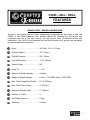
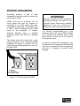
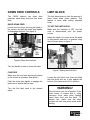
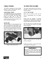
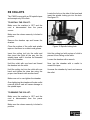
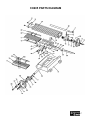
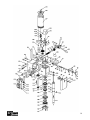
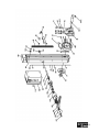
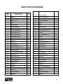
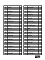
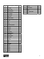
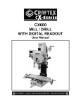
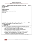
CX605 MINI MILLING MACHINE User Manual TABLE OF CONTENTS General Safety Instructions for Machines ............................................................... 3 Specific Safety Instructions..................................................................................... 4 CX605 Features...................................................................................................... 5 Physical Features ................................................................................................... 6 Proper Grounding ................................................................................................... 7 Setup ...................................................................................................................... 8 Un-Packing ............................................................................................................. 8 Mounting to a Workbench or Stand......................................................................... 9 Assembly ................................................................................................................ 9 Control Panel .......................................................................................................... 9 Test Run ................................................................................................................. 10 Down Feed Controls ............................................................................................... 11 Limit Block .............................................................................................................. 11 Table Travel ............................................................................................................ 12 Tilting The Column.................................................................................................. 12 R8 Collets ............................................................................................................... 13 Spindle RPM ........................................................................................................... 14 Maintenance ........................................................................................................... 14 Gibs Adjustment...................................................................................................... 15 Replacing Motor Brushes........................................................................................ 15 Fuse Replacement.................................................................................................. 16 Lubrication .............................................................................................................. 16 Parts Diagram & Parts List...................................................................................... 17 Warranty ................................................................................................................. 23 2 GENERAL SAFETY INSTRUCTIONS FOR MACHINES Extreme caution should be used when operating all power tools. Know your power tool, be familiar with its operation, read through the owner’s manual, and practice safe usage procedures at all times. ALWAYS read and understand the user manual before operating the machine. CONNECT your machine ONLY to the matched and specific power source. ALWAYS wear safety glasses respirators, hearing protection and safety shoes, when operating your machine. NEVER leave a tool unattended while it is in operation. NEVER allow unsupervised or untrained person to operate the machine. NEVER reach over the table when the tool is in operation. ALWAYS keep blades, knives and bits sharpened and properly aligned. DO NOT wears loose clothing or jewelry when operating your machine. Wear protective hair covering. ALL OPERATIONS MUST BE performed with the guards in place to ensure safety. A SAFE ENVIRONMENT is important. Keep the area free of dust, dirt and other debris in the immediate vicinity of your machine. ALWAYS use push sticks and feather boards to safely feed your work through the machine. BE ALERT! DO NOT use prescription or other drugs that may affect your ability or judgment to safely use your machine. DISCONNECT the power source when changing drill bits, hollow chisels, router bits, shaper heads, blades, knives or making other adjustments or repairs. ALWAYS make sure that any tools used for adjustments are removed before operating the machine. ALWAYS keep bystanders safely away while the machine is in operation. NEVER attempt to remove jammed cutoff pieces until the blade has come to a full stop. 3 CX605 – MINI MILLING MACHINE SPECIFIC SAFETY INSTRUCTIONS READ AND UNDERSTAND the user manual before operating the milling/drilling machine. ALWAYS WEAR safety glasses for the protection of your eyes while operating this machine. WEAR PROPER APPAREL. Loose clothing, gloves neckties, rings, bracelets, or other jewelry may get caught in moving parts of the machine. Wear protective hair covering to contain long hair. Do not wear gloves and keep your fingers and hair away from rotating parts. KEEP GUARDS in place. Safe guards must be kept in place and in working order. Do not operate the milling machine unless the chip guard is in its position, guarding the spindle. MAKE SURE the work-piece is properly clamped to the table before operating the machine. Never hold the work-piece by hands when using the mill. MAKE SURE the cutting tool is sharp, not damaged and properly secured in the chuck before you start the machine. NEVER turn the power ON with the cutting tool contacting the work-piece. SELECT THE PROPER SPINDLE SPEED for the type of work and material you are cutting. Let the spindle reach to its full speed before beginning a cut. DO NOT FORCE THE TOOL. Always use the machine at the rate for which it is designed. Do not force the machine doing a job for which it is not designed. NEVER LEAVE the machine unattended while it is running. ALWAYS turn off the power before removing scrap pieces and cleaning the machine. SHOULD ANY PART of your tool be missing, damaged or fail in any way, shut off the machine immediately and remove the plug from power source. Replace any damaged or missing parts before resuming operation. MAKE SURE before installing and removing any parts, servicing, cleaning or making any adjustments, the switch is in the “OFF” position and the cord is unplugged from the power source. BEFORE OPERATING your CX605 make sure you have read and understood all the safety instructions in the manual and you are familiar with your machine. If you fail to do so, serious injury could occur. WARNING! The safety instructions given above can not be complete because the environment in every shop is different. Always consider safety first as it applies to your individual working conditions. 4 CX605 – MILL / DRILL FEATURES MODEL CX605 – MINI MILLING MACHINE As part of the growing line of Craftex metalworking equipment, we are proud to offer the CX605, a Mini Milling Machine with Variable Speed. By following the instructions and procedures laid out in this user manual, you will receive years of excellent service and satisfaction. The CX605 is a professional tool and like all power tools, proper care and safety procedures should be adhered to. Motor .............................................. 350 Watt, 110-V, 4.5 Amp Drilling Capacity.............................. 1/2" (13mm) End Mill Capacity............................ 5/8” (16mm) Face Mill Capacity .......................... 1-1/8” (30mm) Spindle Taper ................................. R8 Head Tilt ......................................... + - 45° Number of Spindle Speeds............. Variable Range of Spindle Speeds ............... Low:0 – 1100 RPM, High:0 - 2500 RPM Max. Table Longitudinal Travel....... 8-1/2” (220mm) Max. Table Cross Travel................. 4” (100mm) Maximum Spindle Travel ................ 7" (180mm) Number of T-Slots .......................... 3 Net Weight (approx) ....................... 50 Kg Warranty ......................................... 3-Years 5 CX605 MINI MILLING MACHINE PHYSICAL FEATURES 6 PROPER GROUNDING Grounding provides a path of least resistance for electric current to reduce the risk of electric shock. CX605 is for use on a normal 110 volt circuit. Make sure that the machine is connected to an outlet having the same configuration as the plug. If an adaptor plug is used, it must be attached to the metal screw of the receptacle. To prevent electrical hazards, have a qualified electrician ensure that the line is properly wired. The sander should be wired with a plug having 3 prongs to fit a 3 prong grounded receptacle as shown in figure-1. Do not remove the grounding prong to fit it into a 2 pronged outlet. WARNING! Improper connection of the equipmentgrounding conductor can result in a risk of electric shock. Check with a qualified electrician if you are in doubt as to whether the outlet is properly grounded. It is strongly recommended not to use extension cords with your CX605. Always try to position your machine close to the power source so that you do not need to use extension cords. In case if you really find it necessary to use an extension cord, make sure the extension cord does not exceed 50-feet in length and the cord is 14-gauge to prevent motor damage. Figure-1 110-Volts outlet for CX605 7 SETUP Before setting up your machine you should read and understand the instructions given in this manual. The unpainted surfaces of this machine are coated with a rust preventive waxy oil and you will want to remove this before starting assembly. Use a solvent cleaner that will not damage painted surfaces. WARNING! CX605 is a heavy machine, do not overexert yourself. Use a fork truck or get the help of an assistant for safe moving. Before setting up your machine you should read and understand the instructions given in this manual. UNPACKING MOUNTING TO WORKBENCH OR STAND The CX605 features four mounting holes on its base which allows to be mounted on a stand or workbench. To mount the machine on a stand or workbench: Make sure the stand or the workbench is sturdy enough to support a weight of 50 Kg (weight of CX605). The stand or workbench must be level so that the machine is mounted in a stable position. Lift the machine using a fork truck or get the help of an assistant and place it over the stand or workbench. Make sure the machine is centered on the workbench. Locate the four mounting holes on the CX605 base and mark the holes on workbench or stand using a center punch. To ensure safe transportation this machine is properly packaged and shipped completely in carton. When unpacking, carefully inspect the carton and ensure that nothing has been damaged during transit. While doing inventory, if you can not find any part, check if the part is already installed on the machine. Some of the parts come assembled with the machine because of shipping purposes. Figure-2 Mounting holes Remove the machine and drill four holes where you marked the workbench or stand top. Position the machine on the stand or workbench and align the holes on the machine base with the holes on the stand or workbench top. Bolt the machine base properly on the work bench or stand top. 8 ASSEMBLY CONTROL PANEL The hand wheels on your CX605 come installed and you will need to install only the handles on the hand wheels. This section provides information on the CX605 control panel. It is good to get familiar with your machine's control panel before operation. Attach the handles to the longitudinal and cross feed hand wheels and secure the handles by threading the screws using a screwdriver. See figure-3. Figure-4 Control panel Figure-3 Installing the handles onto the hand wheels A. ON & SPEED CONTROL KNOB: The CX605 is a variable speed milling machine and features a speed control knob. This buttons turns the milling machine ON and controls the spindle RPM. B. POWER INDICATOR LIGHT. This light shines when power is ON. C. FUSE SOCKET: system fuse. Houses a 5 amp D. FAULT INDICATOR LIGHT. This light shines when there is a disruption in the system. E. EMERGENCY STOP BUTTON: The CX605 features a large emergency stop button, used to stop the machine in the emergency cases. After using emergency stop button it is necessary to reset the On/ Speed Control Knob. 9 TEST RUN Once you have assembled your milling machine completely, it is then time for a test run to make sure that the machine works properly and is ready for operation. Remove all the tools used for assembling the machine and make sure all the guards are in place. WARNING! Before starting the milling machine, make sure that you have read and understood the manual and you are familiar with the functions and safety features on this machine. Failure to do so may cause serious personal injury or damage to the machine. Connect the cord to the power outlet and turn the machine ON. TO TEST RUN THE CX605: 1. Shift the speed range lever to LOW position. See figure-5. 2. Connect the power cord to the outlet and turn the ON & Speed Control Knob to turn the machine ON. 3. Let the machine run at low speed for 10 minutes and the machine should run smoothly without excessive noise or vibration. If you hear any unusual noise(s) coming from the machine or if it vibrates excessively, shut the machine OFF immediately and disconnect from the power source. Investigate to determine the problem with your machine If the machine runs smoothly, perform as instructed in the next step. 4. Increase the RPM slowly and let the machine run for another 10 minutes. 5. Increase the RPM slowly and let the machine run for another 10 minutes at a high speed. 6. Now, push the Emergency Stop Button in, it should turn the machine OFF. 7. Reset the ON & Speed Control Knob by turning it all the way to left. 8. Shift the speed range lever to HIGH position. See figure-5 and turn the machine ON. 9. Let the machine run at high speed for 10 minutes and slowly increase the RPM, then turn the machine OFF. WARNING! Figure-5 Speed range lever Do not change the speed ranges while machine is running. Failure to do so could result in serious damage to the spindle. 10 DOWN FEED CONTROLS LIMIT BLOCK The CX605 features two down feed methods; rapid down feed and fine down feed. The limit block allows to limit the amount of head travel while down feeding. This feature is used when drilling repeated holes. RAPID DOWN FEED Loosen the lock lever securing the head to the column and pull the down feed handle to disengage the teeth. See figure-6. TO SET THE LIMIT BLOCK: Make sure the machine is OFF and the cord is disconnected from the power source. Select the depth of cut and move the head to that position and lock it in position using the lock lever shown in figure-7. Figure-6 Down feed controls Turn the handle to raise or lower the head. Figure-7 Setting the limit block FINE FEED Make sure the lock lever securing the head to the column is loosened. See figure-7. Push the down feed handle to engage the teeth and to enable the fine feed. Turn the find feed knob to the desired depth. Loosen the limit block lock lever and slide the limit block and set it tight against the bottom of the head and lock it in position. WARNING! The limit block can be off position if the head comes in contact with it, using excessive force while down feeding (rapid down feed and fine feed). To prevent this, make sure the head touches the limit stop gently while down feeding. 11 TABLE TRAVEL TILTING THE COLUMN The CX605 is designed so that the table travels in X and Y axis and the travels is controlled by two hand wheels. The column can be tilted up to 45° either to the right or to the left on vertical axis and locked in position. LONGITUDINAL TRAVEL The longitudinal travel or X axis movement of the table is controlled by a hand wheel at the end of the table. This hand wheel moves the table side to side. The longitudinal movement can be locked in position using the lock lever located on the front of the table. See figure-8. TO TILT THE COLUMN: CROSS FEED The cross feed or Y axis movement of the table is controlled by a hand wheel at the front of the table. This hand wheel moves the table close to or away from the column and it can be locked using the lock lever located underneath the table on the right side of the machine. See figure-8. Make sure the machine is OFF and the cord is disconnected from the power source. Ensure that the machine is securely connected to the workbench or table and the workbench or table is sturdy enough to hold the machine when the column is tilted. Hold the head with one hand and loosen the nut securing the column to the base shown in figure-9. Figure-9 Loosening the nut securing the column to the base Figure- Table travel controls Position the column to the desired angle and retighten the nut properly. WARNING! Make sure to support the head while loosening the nut to prevent the head from falling. Failure to do so could result the falling of the head and personal injury could occur. 12 R8 COLLETS The CX605 comes with an R8 spindle taper and accepts only R8 collets. Locate the hole on the side of the head and insert the spindle locking pin into the hole. See figure-10. TO INSTALL THE COLLET: Make sure the machine is OFF and the cord is disconnected from the power source. Make sure the column securely is locked in position. Remove the drawbar cap and loosen the drawbar. Clean the surface of the collet and spindle taper so that there is no debris and grease. Figure-10 Spindle locking hole Insert the cutting tool into the collet and then insert the collet all the way into the spindle taper untill it touches the threaded end of the drawbar. Hold the cutting tool with a piece of cloth to prevent it from falling on the table. Hold the collet with one hand and thread the drawbar into the collet. Now, tap the drawbar with a mallet to unseat the taper. Hold the cutting tool into the collet with one hand and tighten the draw bar using the proper sized wrench with another hand. Unscrew the drawbar by hand and remove the collet. Loosen the drawbar with a wrench. Make sure not to over-tighten the drawbar. Over-tightening the drawbar will make collet removal difficult and will cause damage to the spindle taper. TO REMOVE THE COLLET: Make sure the machine is OFF and the cord is disconnected from the power source. Make sure the column securely is locked in position. 13 SPINDLE RPM When milling, it is important to select the required spindle RPM for different materials and to ensure safe operation. The CX605 features Low (0-1100 RPM) and High (0-2500 RPM) speed ranges. To select between the high and low speed ranges is very easy. Simply shift the speed range lever to high or low and turn the variable speed control knob to control the spindle RPM. MAINTENANCE During the life of your machine, you will need to practice some regular maintenance to keep your machine in peak performance condition. 1. Treat your machine with care, keep it clean and grease and lubricate it regularly. Only through good care you can be sure that the working quality of the machine will remain constant. 2. During operation, the chips which fall onto the sliding surface should be cleaned in a timely fashion. Frequent inspections should be made to prevent chips from falling into the position between the work table and the slide ways. WARNING! Figure-11 Speed range lever WARNING! Do not change the speed ranges while machine is running. Failure to do so could result in serious damage to the spindle. Do not remove the chips with your bare hands. There is a risk of cut due to sharp-edged chips. Never use flammable solvents or cleaning agents or agents that generate noxious fumes. Protect electrical components such as motors, switches, switch boxes, etc..., against humidity when cleaning. 3. After the operation every day, eliminate all the chips and clean different parts of the machine tool and apply machine tool oil to prevent from rusting. 4. Make sure your work area is well ventilated. 5. Check the machine everyday before operation for; worn or damaged cord, wire, loose nuts and bolts and make sure all the safety devices are working properly. 14 GIBS ADJUSTMENT After a period of time, movement of the work table and the head over the slide ways will cause normal wear that needs to be adjusted. Make sure the adjustments are equal and in small increment. TO ADJUST THE GIB SCREWS: Make sure the machine is OFF and the cord is disconnected from the power source. REPLACING MOTOR BRUSHES After sometimes the carbon brushes on the DC motor will need to be replaced. TO REPLACE THE MOTOR BRUSHES: Make sure the machine is OFF and the cord is disconnected from the power source. Unscrew the cap on the motor shown in figure-13. Locate the work table horizontal adjustment gib screw (A) on the right side of the table and vertical adjustment gib screw (B) on the front side of the table as shown in figure-13. Figure-13 Replacing the motor brushes Figure-12 Adjusting the gib screws Remove the spring and the carbon brush and replace it with new ones. Screw the cap back into the motor housing. Loosen the lock nuts. Move the table and tighten each set screw a little. When the screws are properly adjusted you will feel the resistance. Tighten the lock nuts. 15 FUSE REPLACEMENT LUBRICATION The CX605 features a 4.5 Amp fuse located on the control panel. Apply three to four drops of ISO 68 or similar oil directly to the areas shown in figure-15. TO REPLACE THE FUSE: Make sure the machine is OFF the cord is disconnected from the power source. Turn the button securing the fuse counterclockwise to open. Replace the fuse with a new one and turn the button clockwise to secure the fuse. Figure-15 Lubrication areas Apply a light weight grease every month directly to the cross feed screw, column gear rack and longitudinal lead screw. Figure-14 Replacing the fuse 16 CX605 PARTS DIAGRAM 17 18 19 CX605 PARTS DIAGRAM PART NO. DESCRIPTION QTY 36 Y-axis wedge 1 1 Base 1 37 X-axis screw nut 1 2 Cross leadscrew 1 38 Cap screw M6 x 25 1 3 Key 4 x 16 2 39 Column support 1 4 Dial 2 39―1 Shaft 1 5 Hand wheel 2 39―2 Key 1 7 Handle sleeve 2 40 Spring insert 3 8 Screw M8 x 55 2 40―1 Washer 3 9 Cap screw M6 x 8 7 41 Cap screw M10 x 30 3 10 Holding plate (1) 1 42 Pointer 2 11 Dust guard cover 2 43 Set screw M6 x 22 14 12 Holding plate(2) 2 44 Ruler 1 13 Ball bearing 8200 2 45 Wedge 1 14 Washer 3 46 Gear rack 1 15 Nut M8 6 47 Cap screw M6 x 12 2 16 Y-axis ruler 1 48 Name plate 1 17 Cap screw M6 x 16 4 49 Spindle box 1 18 Y-axis bearing seat 1 50 Gear 1 19 Working table 1 51 Key 1 20 Y-axis feeding screw 1 52 Helical gear 1 21 End cover 1 53 R etaining ring 12 2 22 Screw M6 x 10 2 54 BallΦ5.0 2 23 Y-axis screw nut 1 55 Spring 2 24 Holding plate(3) 1 56 Screw M6 x 8 1 26 Screw seat 1 57 Handle seat 1 29 Nut M6 11 58 Handle 3 30 Handle 4 59 Long handle sleeve 4 31 Screw M6 x 10 2 60 Cap screw M8 x 80 4 32 Pointer 1 61 Pointer 1 34 X-axis wedge 1 63 Spindle box seat 1 35 Saddle 1 64 Wedge 1 20 65 Limit block 1 108 Double head bolt M8 x 70 1 66 Wedge 1 110 Warning label 1 67 Ruler 1 111 Electric box cover 1 68 Column 1 112 Electric box 1 69 Electric box 1 113 Shaft (1) 1 70 Lock nut M24 1 114 key 4 x 45 1 71 Washer 1 116 Spacing ring 1 72 Connecting strut 1 118 Spacing ring 1 75 Screw 4 119 Spindle nut 1 79 Spindle 1 120 key 5 x 18 1 81 Support block 1 121 Cap srew M5 x 12 6 82 Screw M5 x 20 2 122 Bearing cover 2 83 Pin 4 x 16 1 123 Ball bearing 80206E 1 84 Worm 1 124 Name plate 1 85 Sleeve 1 125 Fine feeding laebel 1 86 Pin 3 x 12 2 126 Protecting cover 1 87 Pin 3 x 12 1 127 Motor 1 88 Adjustable union 1 127A Key 1 89 Bracket 1 127B Motor gear washer 1 90 Screw M5 x 25 2 128 Motor gear 1 91 Dial 1 129 Interring ring 9.0 1 92 Damp spring 3 130 Motor seat 1 93 Small hand wheel 1 131 Flat screw M6 x 10 4 94 Screw M4 x 12 1 132 Round screw M5 x 10 1 95 Small shaft 1 133 Yellow lamp 1 96 Cover 1 134 Speed control knob 1 97 Screw M4 x 6 2 135 Green lamp 1 98 Support of dust cover 1 136 Fuse box 1 99 Screw M5 x 16 2 137 Emergency stop switch 1 100 Chip guard 1 138 Gear 1 101 Clamp bolt 1 139 Ball bearing 80101 2 102 Upper end washer 1 140 Transmission gear 1 103 Upper end screw M6 x 16 5 141 Fork 1 104 Set screw M6 x 6 1 142 Linking board 1 107 Handle seat 1 143 Set screw M5 x 8 1 21 144 Self-tapping Screw ST2.9 x6 2 145 H/L label 1 146 Motor cover 1 149 Warming lable 1 150 PC board 1 151 Lock sleeve 1 152 Rotor shaft 1 153 Key 4 x 8 2 154 Spring support 1 155 Torsion spring 1 156 Cover 1 157 Nut 1 158 Prop 1 159 Supporting shank 1 160 Screw 1 161 Washer 2 162 Washer 1 163 Cover 1 164 Top cover 1 166 Spindle gear II 1 167 Set collar 1 168 Spindle gear I 1 169 1 170 Set collar Single-row radial ball bearing 1 171 Key 1 172 Key 1 200 Dial seat 1 201 Screw 4 202 Rivet 10 203 Screw 1 204 Screw 3 205 Screw 2 206 Washer 1 207 Screw 1 208 Fixed sleeve 1 209 Washer 1 210 Shaft 1 211 R8 Taper-shank 1 212 Key 1 22 WARRANTY CRAFTEX 3 YEARS LIMITED WARRANTY Craftex warrants every product to be free from defects in materials and agrees to correct such defects where applicable. This warranty covers three years for parts and 90 days for labor (unless specified otherwise), to the original purchaser from the date of purchase but does not apply to malfunctions arising directly or indirectly from misuse, abuse, improper installation or assembly, negligence, accidents, repairs or alterations or lack of maintenance. Proof of purchase is necessary. All warranty claims are subject to inspection of such products or part thereof and Craftex reserves the right to inspect any returned item before a refund or replacement may be issued. This warranty shall not apply to consumable products such as blades, bits, belts, cutters, chisels, punches etceteras. Craftex shall in no event be liable for injuries, accidental or otherwise, death to persons or damage to property or for incidental contingent, special, or consequential damages arising from the use of our products. RETURNS, REPAIRS AND REPLACEMENTS To return, repair, or replace a Craftex product, you must visit the appropriate Busy Bee Tools showroom or call 1800-461-BUSY. Craftex is a brand of equipment that is exclusive to Busy Bee Tools. For replacement parts directly from Busy Bee Tools, for this machine, please call 1-800-461-BUSY (2879), and have your credit card and part number handy. All returned merchandise will be subject to a minimum charge of 15% for re-stocking and handling with the following qualifications. Returns must be pre-authorized by us in writing. We do not accept collect shipments. Items returned for warranty purposes must be insured and shipped pre-paid to the nearest warehouse Returns must be accompanied with a copy of your original invoice as proof of purchase. Returns must be in an un-used condition and shipped in their original packaging a letter explaining your reason for the return. Incurred shipping and handling charges are not refundable. Busy Bee will repair or replace the item at our discretion and subject to our inspection. Repaired or replaced items will be returned to you pre-paid by our choice of carriers. Busy Bee reserves the right to refuse reimbursement or repairs or replacement if a third party without our prior authorization has carried out repairs to the item. Repairs made by Busy Bee are warranted for 30 days on parts and labour. Any unforeseen repair charges will be reported to you for acceptance prior to making the repairs. The Busy Bee Parts & Service Departments are fully equipped to do repairs on all products purchased from us with the exception of some products that require the return to their authorized repair depots. A Busy Bee representative will provide you with the necessary information to have this done. For faster service it is advisable to contact the nearest Busy Bee location for parts availability prior to bringing your product in for repairs. 23