1
Low end control
Telemecanique
The essential guide
2006
General contents
I ntroduction
Telemecanique,
b the Schneider
Electric brand for
Automation & Control.
b innovative
products…
Automation
b Plug-in Relays
b Timers, Counters, Control Relay, Analog Interfaces
b Distributed Inputs/Outputs
b Zelio Logic Smart Relays
b Twido, Nano PLC
1
Power supplies
b DC Power supplies
b Transformers for control circuits
2
Interfaces and I/O
b Term blocks & Cable ends
b Interfaces and distributed Inputs/Outputs
3
AS-Interface cabling system
b The cabling system that meets your needs for industrial automation
systems
4
Telemecanique,
the Schneider Electric brand for
Automation & Control
Used together or separatley, Telemecanique products
can provide complete functionalities for all of your
industrial, building, infrastructure, and energy automation
applications.
Operator dialog
Software tools
Systems & Architectures
Motion and Drives
Automation
Interfaces & I/O
Motor control
Detection
Power supplies
Known for its quality
and innovation for
over 80 years,
Telemecanique
offers a wide range
of products in over
130 countries
around the world.
TeSys motor starters
Altivar drives
Altistart soft starters
Lexium motors and servo-drives
Advantys distributed I/O
Zelio relays and Twido controllers
Modicon PLCs
Unity automation hardware
and software solution (NEW !)
Magelis operator terminals
Harmony control and signalling units
Osiconcept sensors
Preventa safety solutions
etc.
Other versions: please consult your Schneider Electric agency.
2
Simply Smart !
Leveraging ingenuity and intelligence for ease of use
Simplicity
p
Cost effective “optimum”
offers that make selection
easy for most typical
applications
p Products that are easy to
understand for users,
electricians and
automation specialists
p User-friendly intuitive
programming,
…for example
Zelio Logic
Easy programming directly
on the smart module with
either the Compact or
Modular versions, or via
PC using FBDs or Ladder
Logic. Control of
applications by simply
sending an SMS...
Ingenuity
Openness
p Auto-adapts to its
environment, “plug & play”
p Application functions,
control, communication
and diagnostics embedded
in the products
p User-friendly operation
either directly on the
product or remotely
p
…for example
Altivar 71
“Plug & drive” speed drive
with functionality adapted
specifically for pumps and
fans, solutions with
harmonics protection and
PowerSuite software for
pocket PCs, perfectly suited
for building applications!
Flexibility
p
Interchangeable
modular functions, to
better meet the
requirements for
extensions
p Software and
accessories common to
multiple product families
…for example
Twido
Programmable controller
with “compact” or
“modular” versions to
better meet your needs.
Its flexibility enables you
to add options like a
display, communication
bus, more memory,….
Compliance with field bus,
connection, and software
standards
p Enabling decentralised
or remote surveillance
via the web with
Transparent Ready
products
…for example
TeSys U
The first starter controller
to integrate motor power
and control functions,
adaptable to a variety of
standard buses, and
permits you to
transparently monitor
applications via the web.
Compactness
High functionality in a
minimum of space
p Freedom in implementation
p
…for example
Magelis XBT GT
Besides the fact that it is
the most compact semigraphic display on the
market, it offers a high
degree of legibility,
configurable keys, and
multi-language
management capabilities.
Other versions: please consult your Schneider Electric agency.
3
Telemecanique,
innovative products for all Automation & Control functions.
Machine safety
See Machine safety
in each function
Operator dialog
AS-Interface
Systems & Architectures
See AS-Interface
in each function
Interfaces & I/O
Detection
Operator dialog
Interfaces & I/O
Control & signalling units
Control and signalling units,
cam switches
Beacons and indicator banks
Connectors
Cable-ends, terminal blocs
Interfaces
Plug-in relays, analog
converters, discrete
interfaces
Pre-wired interfaces,
IP20/IP67 distributed I/O
AS-Interface
IP20/IP67 interfaces,
cables, repeaters,
accessories,adressing and
adjustment terminals
Machine safety
Safety monitors and
controllers on AS-Interface
Software
Software to design and
install AS-Interface system,
safety monitors and
controllers on AS-Interface
programming software
Detection
Human machine interfaces
Operator interface terminals,
industrial PCs, Web servers,
HMI and SCADA PC-based
software
Sensors
Limit switches
Proximity sensors
Photo-electric and ultrasonic
sensors
Pressure switches
Rotary encoders
Control stations, mounting
solutions
Control and pendant
stations, front panels
mounting kits
RFID, vision
Inductive identification
Vision system
AS-Interface
Control stations, keypads,
beacons
Machine safety
Switches, light curtains,
mats
Machine safety
Emergency stops, control
stations, enabling switches,
foot switches
Software
Safety mats configuration
software
Software
Operator terminal software
Mounting systems
Systems &
Architectures
Connecting Ethernet
devices
Web-enabling PLCs
on Ethernet
Application protocols
and field buses
Enclosures
Wall mounted enclosures
Floor standing enclosures,
suite type cubicles
Industrial boxes
Equipment and accessories
Thermal control equipment
Power splitter blocks
Mounting accessories
Other versions: please consult your Schneider Electric agency.
4
Simply Smart !
Software tools
Motion and Drives
Automation
Motor control
Power supplies
Automation
Motor control
Relays
Plug-in relays, electronic
timers, control relays,
counts
Smart relays
Motor starters
Contactors
Circuit breakers, fuse carriers
Thermal relays
Combinations, motor
controllers
PLCs, PC based control,
distributed I/O
Programmable controllers
PLC platforms
PC based control
Distributed I/O, I/O
controllers
AS-Interface
Master modules for
Modicon PLCs
Mounting solutions
Motor starter mounting kit
Motion and Drives
Software tools
Machine safety
Safety PLCs, controllers
and modules
Global software
Generation of application
systems
Application control
Collaborative development
Software
PLCs and safety controllers
programming software
Dedicated software
See Software in other
functions
Power supplies
Power supplies
Switch mode power
supplies
Filtered rectified power
supplies, transformers
AS-Interface
Power supplies
AS-Interface
Motor controllers,
enclosures, variable speed
drives
Starters, drives and
servo drives
Soft starters
Variable speed drives
Motion modules
Servo drives
Servo motors
Machine safety
Switch disconnectors,
thermal-magnetic motor
circuit breakers, enclosed
starters
Software
Software for drives
and motors
Software
Motor control programming
software
Other versions: please consult your Schneider Electric agency.
5
Automation
Ingenious solutions for all
your automation system
applications
Perfect suitability for all your applications thanks to a complete offer...
from simple relays to automation platforms.
Relays and Zelio Logic smart relays
Zelio
Zelio relay range
Zelio Relay plug-in relays, Zelio Control
control and measurement relays, Zelio Count
counters, Zelio Time timing relays: These
ranges offer compactness and simplicity.
Twido
Zelio Logic smart relays
Designed for management of simple
automation systems comprising 10 to 40 I/O.
Compact or modular, Zelio Logic offers
flexibility and simplicity.
Programmable controllers
Twido, ideal for simple installations and
small machines: standard applications
comprising 10 to 100 I/O (max. 252 I/O).
Compact or modular, Twido offers flexibility
and simplicity.
The essential
guide
A simplified
selection guide
enabling you to
quickly select all
the products
required to
develop an
automation
system... from a
small simple
machine
to a complex
installation.
Other versions: please consult your Schneider Electric agency.
Contents
b Zelio Relay - Plug-in relays ........................................................ 8-9
b Zelio Analog - Analog interface ..............................................10-11
b Zelio Control - Control and measurement relays ........................ 12
b Zelio Count - Counters ................................................................13
b Zelio Time - Timing relays .......................................................14-15
b Zelio Logic - Smart relays ...................................................... 16-17
b Twido - Nano PLC................................................................... 18-19
With Transparent Ready,
Schneider Electric has applied market
standards to its automation system
architectures, making data exchange
even easier. Smart and simple to use,
the Telemecanique software offer
ensures maximum efficiency in terms
of application development and
maintenance, while its high
performance Telemecanique PLCs
help to achieve optimum installation
availability and productivity. Committed
to maximising your investment over the
long-term, Schneider Electric makes it
easy for you to develop your
applications with complete peace of
mind.
Other versions: please consult your Schneider Electric agency.
Zelio Relay
Plug-in relays
Interface and miniature relays
Type of relay
Interface relays
RSB
U
R
Miniature relays
RXM
Contact characteristics
C
Thermal current Ith in A (temperature ≤ 55°C)
8
12
16
12
10
6
3
10
Number of contacts
2 “C/O”
1 “C/O”
1 “C/O”
2 “C/O”
3 “C/O”
4 “C/O”
4 “C/O”
2
Contact material
AgNi
AgNi
AgNi
AgNi
AgNi
AgNi
AgAu
Switching voltage, min. / max.
5 / 250 VAC/DC
Switching capacity, min. / max. (mA / VA)
5 / 2000
5 / 3000
5 / 4000
10 / 3000
10 / 2500
A
12
12 / 250 VAC/DC
10 / 1500
2 / 1500
10
Coil characteristics
2
Average consumption, inrush,
0.75 VA / 0.45 W
1.2 VA / 0.9 W
Permissible voltage variation
0.8/0.85…1.1 Un (50 / 60Hz or =)
0.8…1.1 Un (50 / 60Hz or =)
(1)
(2)
Catalogue numbers
(1)
(1)
(2)
–
–
–
RXM3AB2JD
RXM4AB2JD
RXM4GB2JD
R
24 VDC RSB2A080BD RSB1A120BD RSB1A160BD RXM2AB2BD RXM3AB2BD RXM4AB2BD RXM4GB2BD
R
6 VDC RSB2A080RD RSB1A120RD RSB1A160RD –
12 VDC RSB2A080JD
on DC
(2
(2)
–
Coil supply voltage
RSB1A120JD
RSB1A160JD
RXM2AB2JD
48 VDC RSB2A080ED RSB1A120ED RSB1A160ED RXM2AB2ED RXM3AB2ED
RXM4AB2ED RXM4GB2ED
R
60 VDC RSB2A080ND RSB1A120ND RSB1A160ND –
–
–
–
–
R
110 VDC RSB2A080FD RSB1A120FD RSB1A160FD RXM2AB2FD
RXM3AB2ED
RXM4AB2ED RXM4GB2ED
Coil supply voltage
24 VAC RSB2A080B7 RSB1A120B7 RSB1A160B7 RXM2AB2B7
RXM3AB2B7
RXM4AB2B7
RXM4GB2B7
R
on AC
48 VAC RSB2A080E7 RSB1A120E7 RSB1A160E7 RXM2AB2E7
RXM3AB2E7
RXM4AB2E7
RXM4GB2E7
R
R
120 VAC RSB2A080F7 RSB1A120F7 RSB1A160F7 RXM2AB2F7
RXM3AB2F7
RXM4AB2F7
RXM4GB2F7
220 VAC RSB2A080M7 RSB1A120M7 RSB1A160M7 –
–
–
–
–
230 VAC RSB2A080P7 RSB1A120P7 RSB1A160P7 RXM2AB2P7
RXM3AB2P7
RXM4AB2P7
RXM4GB2P7
R
240 VAC RSB2A080U7 RSB1A120U7 RSB1A160U7 –
–
–
RXM4GB2U7
–
Sockets for relays
Type of socket
F
For interface relays RSB
For miniature relays RXM
–
–
–
RXZE2M114(5) –
RXZE2M114
–
–
–
RXZE2M114M(5) –
RXZE2M114M RXZE2M114M
–
RSZE1S48M RSZE1S35M RSZE1S48M(3) RXZE2S108M RXZE2S111M RXZE2S114M RXZE2S114M
R
Mixed input/output type sockets with location for protection module
RXZE2M114
R
Separate input/output type sockets with location for protection module
Protection modules
Diode
6…230 VDC
RZM040W
RXM040W
R
RC circuit
24…60 VAC
RZM041BN7
RXM041BN7
–
110…240 VAC
RZM041FU7
RXM041FU7
R
6…24 VDC or AC
RZM021RB (6)
RXM021RB
–
–
Varistor
24…60 VDC or AC
RZM021BN (6)
RXM021BN
110…230 VDC or AC
RZM021FP (6)
RXM021FP
–
24 VDC or AC
–
–
R
240 VDC or AC
–
–
R
24…230 VDC or AC
–
–
R
Plastic maintaining clamp
RSZR215
RXZR335
–
Metal maintaining clamp
–
RXZ400
R
Label for socket
RSZL300
RXZL420 (except RXZE2M114)
R
Multifunction timer module
Accessories
–
RXZS2
R
DIN rail adapter
–
RXZE2DA
–
Panel mounting adapter
–
RXZE2FA
Bus jumper
2 poles
–
(1) References for relays without socket, for relays with socket, add the letter S to the end of the selected reference. (Example: RSB2A080B7 becomes RSB2A080B7S).
(4)
(2) References for relays with LED, for relays without LED, replace the number 1 in the reference by 2. (Example: RXM2AB2JD becomes RXM2AB1JD)
(5)
(3) To use RSB 1A160 pp relay with socket, terminals must be interconnected
(6)
Other versions: please consult your Schneider Electric agency.
8
Universal and power relays
Universal relays
RUM
Power relays
RPM
Cylindrics
10
10
3
10
10
15
15
15
15
30 (4)
30 (4) (7)
2 “C/O”
3 “C/O”
3 “C/O”
2 “C/O”
3 “C/O”
1 “C/O”
2 “C/O”
3 “C/O”
4 “C/O”
2 “N/O”
2 “C/O”
AgNi
AgNi
AgAu
AgNi
AgNi
AgNi
AgNi
AgNi
AgNi
AgSnO2
AgSnO2
12 / 250 VAC/DC
10 / 2500
10 / 2500
BD
ED
12 / 250 VAC/DC
12 / 250 VAC/DC
3 / 750
10 / 2500
10 / 2500
100 / 3750
100 / 3750
100 / 3750
100 / 3750
0.9 VA / 0.7 W 1.2 VA / 0.9 W 1.5 VA / 1.7 W 1.5 VA / 2 W
2…3 VA / 1.4 W
D
RPF
Faston
100 / 7200
100 / 7200
4 VA / 1.7 W
(2)
(2)
–
(2)
(2)
(2)
(2)
(2)
(2)
–
–
–
–
–
–
–
–
–
–
–
–
–
RUMF2AB2JD RUMF3AB2JD RPM12JD
RPM22JD
RPM32JD
RPM42JD
RPF2AJD
RPF2BJD
RUMC2AB2BD RUMC3AB2BD RUMC3GB2BD RUMF2AB2BD RUMF3AB2BD RPM12BD
RPM22BD
RPM32BD
RPM42BD
RPF2ABD
RPF2BBD
RUMC2AB2JD RUMC3AB2JD –
RUMC2AB2ED RUMC3AB2ED RUMC3GB2ED RUMF2AB2ED RUMF3AB2ED RPM12ED
RPM22ED
RPM32ED
RPM42ED
–
–
–
–
–
–
–
–
–
–
–
–
–
ED
RUMC2AB2FD RUMC3AB2FD –
RUMF2AB2FD RUMF3AB2FD RPM12FD
RPM22FD
RPM32FD
RPM42FD
RPF2AFD
RPF2BFD
B7
RUMC2AB2B7 RUMC3AB2B7 RUMC3GB2B7 RUMF2AB2B7 RUMF3AB2B7 RPM12B7
RPM22B7
RPM32B7
RPM42B7
RPF2AB7
RPF2BB7
–
E7
RUMC2AB2E7 RUMC3AB2E7 RUMC3GB2E7 RUMF2AB2E7
RUMF3AB2E7
RPM12E7
RPM22E7
RPM32E7
RPM42E7
–
7
RUMC2AB2F7 RUMC3AB2F7 RUMC3GB2F7 RUMF2AB2F7
RUMF3AB2F7
RPM12F7
RPM22F7
RPM32F7
RPM42F7
RPF2AF7
RPF2BF7
–
–
–
–
–
–
–
–
–
P7
U7
–
–
RUMC2AB2P7 RUMC3AB2P7 RUMC3GB2P7 RUMF2AB2P7
RUMF3AB2P7
RPM12P7
RPM22P7
RPM32P7
RPM42P7
RPF2AP7
RPF2BP7
–
–
–
–
–
–
–
–
–
–
–
For universal relays RUM
For power relays RPM
For power relays RPF
RUZC2M
RUZC3M
RUZC3M
–
–
RPZF1
RPZF2
RPZF3
RPZF4
–
4M
–
–
–
–
–
–
–
–
–
–
4M
RUZSC2M
RUZSC3M
RUZSC3M
RUZSF3M
RUZSF3M
–
–
–
–
–
4
3 and 4 poles
1 and 2 poles
RUW240BD
RXM040W
RUW240BD
–
–
RXM041BN7
–
–
RUW241P7
RXM041FU7
RUW241P7
–
–
RXM021RB
–
–
–
RXM021BN
–
–
–
RXM021FP
–
–
RUW242B7
RUW242B7
–
–
RUW242P7
–
RUW242P7
–
RUW101MW
–
RUW101MW
–
–
–
–
RUZC200
RPZF1 (for 1 pole relays)
–
RUZL420
–
–
RUZS2
–
–
RPZ1DA
RXZE2DA
RPZ3DA
RPZ4DA
–
–
RPZ1FA
RXZE2FA
RPZ3FA
RPZ4FA
–
(4) 30A with 13 mm space between relays; 25 A when relay mounting side by side
–
(7) 30A for “NO”, 3A for “NC”
(5) Max 10 A operating
(6) With LED
Other versions: please consult your Schneider Electric agency.
9
Zelio Analog
Analog Interface
Universal Thermocouple
Type
Temperature range
Thermocouple
0…150 °C
0…300 °C
0…600 °C
0…600 °C
0…1200 °C
32…302 °F
32…572 °F
32…1112 °F
32…1112 °F
32…2192 °F
RMTJ80BD
RMTK80BD
RMTK90BD
Output range
0…10 V / 0…20 mA - 4…20 mA Switchable
Dimensions H x W x D
80 x 22,5 x 80 mm
Voltage
24 VDC - Non isolated
Catalogue numbers
RMTJ40BD
RMTJ60BD
Universal PT 100
Type
Temperature range
PT 100
-40…40 °C
-100…100 °C
0…100 °C
0…250 °C
0…500 °C
-40…104 °F
-148…212 °F
32…212 °F
32…482 °F
32…932 °F
RMPT50BD
RMPT70BD
Output range
0…10 V / 0…20 mA - 4…20 mA Switchable
Dimensions H x W x D
80 x 22,5 x 80 mm
Voltage
24 VDC - Non isolated
Catalogue numbers
RMPT10BD
RMPT20BD
RMPT30BD
Other versions: please consult your Schneider Electric agency.
10
Optimum PT 100
Type
Temperature range
PT 100
-40…40 °C
-100…100 °C
0…100 °C
0…250 °C
0…500 °C
-40…104 °F
-148…212 °F
32…212 °F
32…482 °F
32…932 °F
RMPT33BD
RMPT53BD
RMPT73BD
Output range
0…10 V
Dimensions H x W x D
80 x 22,5 x 80 mm
Voltage
24 VDC - Non isolated
Catalogue numbers
RMPT13BD
RMPT23BD
Universal Analog Converter
Type
Analog Converter
Input range
0…10 V or 4…20 mA
0…10 V / -10…+10 V
0…50 V / 0…300 V
0…1,5 A / 0…5 A
0…20 mA
0…500 V
0…15 A
4…20 mA
Output range
0…10 V or 4…20 mA
0…10 V / -10…+10 V
0…10 V
0…10 V or 0…20 mA
0…20 mA
0…20 mA
ou 4…20 mA
4…20 mA Switchable
4…20 mA Switchable
Dimensions H x W x D
80 x 22,5 x 80 mm
Voltage
24 VDC - Non isolated
24 VDC - Isolated
24 VDC - Non isolated
24 VDC - Non isolated
Catalogue numbers
RMCN22BD
RMCL55BD
RMCV60BD
RMCA61BD
80 x 45 x 80 mm
Other versions: please consult your Schneider Electric agency.
11
Zelio Control
Relays
Control relays for 3-phase supplies
Function
Rotational direction and presence of phases
+ Undervoltage + Over and undervoltage
+ Asymmetry
+ undervoltage
+ Asymmetry
Adjustable time delay
without
without
0.1…10 s
0.1…10 s
fixed, 0.5 s
0.1…10 s
Supply voltage
220…440V
380…440V
400V
380…440V
380…440V
380…440V
600 V
Output
2 C/O
2 C/O
2 C/O
2 C/O
1 C/O
2 C/O
2 C/O
Catalogue numbers
RM4TG20
RM4TU02
RM4TR34 (1)
RM4TR32 (2)
RM4TA02
RM4TA32
8430MPDV32 (3)
without
(1) Relay with fixed voltage thresholds.
(2) Relay with adjustable voltage thresholds.
Current and voltage measurement relays
(3) Part of our Square D line of control
relays for 3 phase supplies
(4) Basic reference. To be completed with the letters
indicating the required voltage, as shown below:
VAC, 50/60 Hz
VDC
MW
MW
110…130 V
F
–
220…240 V
M
–
380…415 V
Q
–
Voltage
24…240 V
Function
Detection of
over and undercurrent
over and undercurrent
Measuring range
3…30 mA
0.3…1.5 A
0.05 …0.5 V
1…10 V
30…300 V
10…100 mA
1…5 A
0.3 …3 V
5…50 V
50…500 V
10…100 V
180…270 V
0.1…1 A
3…15 A
0.5…5 V
Adjustable time delay
0.05…30 s
0.05…30 s
0.05 …30 s
0.05…30 s
0.05…30 s
0.1…10 s
Output
2 C/O
2 C/O
2 C/O
2 C/O
2 C/O
2 C/O
Catalogue numbers
RM4JA31•• (4)
RM4JA32•• (4)
RM4UA31•• (4) RM4UA32•• (4) RM4UA33•• (4) RM4UB35
Liquid level control relays
(5) Basic reference. To be completed with the letters
indicating the required voltage, as shown below:
RM4-LG01
RM4-LA32
VAC, 50/60 Hz
VAC, 50/60 Hz
VDC
24 V
B
B
–
MW
Voltage
24…240 V
–
MW
110…130 V
F
F
–
220…240 V
M
M
–
380…415 V
Q
Q
–
Control relays
Empty or fill
Sensitivity scale
5 ... 100 kΩ
0.25 ... 5 kΩ
2.5 ... 50 kΩ
25 ... 500 kΩ
Time delay
without
adjustable, 0.1 to 10 s
Output
1 C/O
2 C/O
Catalogue numbers
RM4LG01• (5)
RM4LA32•• (5)
Liquid level control probe type
Measuring electrode and
reference electrode
1 simple stainless steel electrode
in PVC protective casing
Mounting
suspended
suspended
Maximum operating temperature
100°C
100°C
Catalogue numbers
LA9RM201
RM79696043
Other versions: please consult your Schneider Electric agency.
12
Zelio Count
Counters
Totalisers
Display
Mechanical
LCD
Supply voltage
24 VDC
Number of digits displayed
5
6
6
8
Counting frequency
20 Hz
10 Hz
25 Hz
25 Hz
7.5 kHz
Type of zero reset
Front panel
Without
Front panel
Without
Front panel (1)
Front face dimensions, W x H
41.5 x 31 mm
30 x 20 mm
60 x 50 mm
60 x 50 mm
48 x 24 mm
Certification
UL cUR
–
UL cUR, CSA
cUR
–
Battery
8
Type of input
Contact
Contact
Contact
Contact
Volt free contact or transistor
Front face protection
IP40
IP65
IP40
IP40
IP54
Catalogue numbers
XBKT50000U10M
XBKT60000U00M
XBKT60000U10M
XBKT80000U00M
XBKT81030U33E
(1) With electrical interlocking.
Totalisers
Display
Mechanical
Supply voltage
115 V
LCD
115 V
Battery
Number of digits displayed
5
6
8
6
6
8
Counting frequency
10
10
40 Hz
14 Hz or 100 Hz
14 Hz
40 Hz/7kHz
Type of input
Contact
Contact
Voltage
Contact/Solid state
Voltage
Slow input-volt free contact
or NPN translator.
Fast input-voltage
Type of zero reset
Front panel
Front panel
Front panel (2)
External voltage
Front Panel for Partial counter/Front panel or
external contact for total reset
Front Panel (3)
External contact
Front face dimensions W x H
41.5 x 31
Front face protection
IP40
IP40
IP56
IP56
IP66
IP66
Certification
UL, cUR
UL, cUR
cULus, CSA
cULus, CSA
cULus, CSA
cULus, CSA
Catalogue numbers
XBKT5000U11M XBKT6000U11M
RC87610050
RC87610240
RC87610250
RC87810340
48 x 24 mm
(2) Reset can be inhibited by switch setting on the unit. (3) External contact required to enable reset.
Hour counters
Display
LCD
LCD
LCD
Supply voltage
Battery
Battery
Battery
6
8 (999,999.99 h)/(Mode: 1/100 hour)
Number of digits / display
6
Type of input
Volt free contact
Voltage
Transistor
Type of zero reset
Front Panel (3)/External contact
Front Panel (2)/External contact
Front Panel (1)
Front face dimensions, W x H
48 x 24 mm
48 x 24 mm
48 x 24 mm
Front face protection
IP64
IP68
IP54
Certification
cULus, CSA
cULus, CSA
–
Catalogue numbers
RC87610440
RC87610150
XBKH8100 0033E
(1) With electrical interlocking. (2) Reset can be inhibited by switch setting on the unit. (3) External contact required to enable reset.
Multifunction counters
Display
LCD
Number of digits displayed
6
LED
Counting frequency
5 kHz
Type of reset
Manual, electric and automatic
Front face dimensions, W x H
48 x 48 mm
Preselection number
1
2
1
2
Certification
UL cUR
UL cUR
UL cUR
UL cUR
Front face protector
Catalogue numbers
Supply voltage
IP65
IP65
IP65
IP65
24 VDC
XBKP61130G30E
XBKP61230G30E
XBKP62130G30E
XBKP62230G30E
115 VAC
XBKP61130G31E
XBKP61230G31E
–
–
230 VAC
XBKP61130G32E
XBKP61230G32E
XBKP62130G32E
XBKP62230G32E
Other versions: please consult your Schneider Electric agency.
13
Zelio Time
Timing relays
Modular timers
Type of modular timer
width 17.5 mm, relay output
On-delay
Multifunction
External control
no
–
–
Supply voltage
24 VDC - 24 ...240 VAC
24 VDC - 24 ...240 VAC
12 ... 240VAC/DC
Timing range
0.1 s…100 h
0.1 s…100 h
0.1 s…10 h
0.1 s…100 h
Output
1 C/O
1 C/O
1 C/O
1 C/O
Catalogue numbers
RE11RAMU
RE11RMMU (1)
RE11RMEMU (2)
RE11RMMW (1)
(1) Multifunction: On-delay, Off-delay, Totaliser, Symmetrical flashing, Chronometer, Pulse on energisation, Pulse output, Timing after closing/opening of control contact.
(2) Multifunction: On-delay, Off-delay, Totaliser, Symmetrical flashing, Chronometer, Pulse on energisation.
Off delay
Type of modular timer
width 17.5 mm, relay output
Asymmetrical
flashing
Pulse on
energisation
Chronometer
External control
–
–
–
–
Supply voltage
24 VDC - 24…240 VAC
24 VDC - 24…240 VAC
24 VDC - 24…240 VAC
24 VDC - 24…240 VAC
0.1 s…100 h
Timing range
0.1 s…100 h
0.1 s…100 h
0.1 s…100 h
Output
1 C/O
1 C/O
1 C/O
1 C/O
Catalogue numbers
RE11RLMU
RE11RHMU
RE11RCMU
RE11RBMU
Type of modular timer
width 17.5 mm, solid-state output
On-delay
Off-delay
Multifunction (3)
Supply voltage
24…240 VAC/DC
24…240 VAC
24…240 VAC
Timing range
0.1 s…100 h
0.1 s…100 h
0.1 s…100 h
Output
solid-state
solid-state
solid-state
Catalogue numbers
RE11LAMW
RE11LCBM
RE11LMBM
(3) Multifunction: On-delay, Off-delay, Totaliser, Symmetrical flashing, Chronometer, Pulse on energisation, Pulse output, Timing after closing/opening of control contact.
Panel-mounted relays
Timer on-delay
Power supply
24…240 VAC/DC
Time range
0,02 s…300 h
Output
2 relay 5 A
Catalogue numbers
RE48ATM12MW
Asymmetrical
flasher
Multifunction (4)
Multifunction (5)
RE48ACV12MW
RE48AMH13MW (6)
RE48AML12MW
(4) Timer on-delay / pulse on energization
(5) Timer on-delay / calibrator / timer off-delay / symmetrical flasher
(6) 1 selectable in instantaneous
Other versions: please consult your Schneider Electric agency.
14
Industrial timers
Type of single function relay
width 22.5 mm, relay output
On-delay
Off-delay
External control
no
yes
no
yes
Supply voltage
24 VAC/DC
24 VAC/DC
24...240 VAC/DC
24 VAC/DC
24 VAC/DC
110…240 VAC
42…48 VAC/DC
42…48 VAC/DC
42…48 VAC/DC
110…240 VAC
110…240 VAC
110…240 VAC
yes
Timing range
0.05 s...300 h
0.05 s...300 h
0.05 s...10 mn
0.05 s...300 h
0.05 s…300 h
Output
1 C/O
2 C/O (1)
1 C/O
2 C/O (1)
1 C/O
Catalogue numbers
RE7TL11BU
RE7TP13BU
RE7RB11MW
RE7RL13BU
RE7RM11BU
(1) 1 selectable in instantaneous mode.
Type of relay
width 22.5 mm, relay output
Single function
Asymmetrical flashing
Pulse on energisation
Multifunction
6 functions (2)
External control
yes
no
–
–
Supply voltage
24 VAC/DC
24 VAC/DC
24 VAC/DC
24 VAC/DC
42…48 VAC/DC
110…240 VAC
42…48 VAC/DC
110…240 VAC
110…240 VAC
8 functions (3)
110…240 VAC
Timing range
0.05 s...300 h
0.05 s...300 h
0.05 s…300 h
0.05 s…300 h
Output
1 C/O
1 C/O
1 C/O
2 C/O (4)
Catalogue numbers
RE7CV11BU
RE7PE11BU
RE7ML11BU
RE7MY13BU
(2) RE7ML11BU functions: On-delay, Off-delay, Pulse on energisation with start on energisation, Pulse on energisation with start on opening of remote control contact, Flashing with
start during the OFF period, Flashing with start during the ON period.
(3) REMY13BU functions: On-delay, Off-delay, Pulse on energisation with start on energisation, Pulse on energisation with start on opening of remote control contact, Flashing with
start during the OFF period, Flashing with start during the ON period, Star-delta starting with double On-delay timing, Star-delta starting with contact for switching to star connection.
(4) 1 selectable in instantaneous mode
Miniature plug-in relays, relay output
Functions
Timing ranges
7 switchable ranges
0.1 s…1 s - 1 s…10 s - 0.1 min…1 min - 1 min…10 min - 0.1 h…1 h - 1 h…10 h - 10 h…100 h
Relay output
4 timed C/O contacts
2 timed C/O contacts
Rated current
AC 3 A
AC 5 A
Voltages
24 VDC
RE XL4TMBD
RE XL2TMBD
24 VAC 50/60 Hz
RE XL4TMB7
RE XL2TMB7
120 VAC 50/60 Hz
RE XL4TMF7
RE XL2TMF7
230 VAC 50/6 0 Hz
RE XL4TMP7
RE XL2TMP7
Other versions: please consult your Schneider Electric agency.
15
Zelio Logic
Smart relays
Compact, SR2
Compact smart relays
With display, d.c. power supply
Supply voltage
12 VDC
Number of inputs/outputs
12
20
10
12
20
20
Discrete inputs
8
12
6
8
12
12
including 0-10 V analogue inputs
4
6
-
4
2
6
Number of outputs
4 relay
8 relay
4 relay
4
8 relay
8
Dimensions, W x D x H (mm)
71.2x59.5x107.6
124.6x59.5x107.6 71.2x59.5x107.6
Clock
yes
yes
no
yes
no
yes
Catalogue numbers
SR2B121JD
SR2B201JD
SR2A101BD (1)
SR2B12p
pBD (2)
SR2A201BD (1)
SR2B20p
pBD (2)
Number of inputs
24 VDC
124.6x59.5x107.6
(1) Programming on smart relay in LADDER language only
(2) Replace the p by the number 1 to order a smart relay with relay output or by 2 for a smart relay with transistor output (Example: SR2B121BD)
Compact smart relays
With display, a.c. power supply
Supply voltage
24 VAC
Number of inputs/outputs
12
20
10
12
20
20
8
12
6
8
12
12
4 relay
4 relay
8 relay
8 relay
Number of inputs
Discrete inputs
100…240 VAC
Number of outputs
4 relay
8 relay
Dimensions, W x D x H (mm)
71.2x59.5x107.6
124.6x59.5x107.6 71.2x59.5x107.6
124.6x59.5x107.6
Clock
yes
yes
no
yes
no
yes
Catalogue numbers
SR2B121B
SR2B201B
SR2A101FU (1)
SR2B121FU
SR2A201FU (1)
SR2B201FU
(1) Programming on smart relay in LADDER language only
Compact smart relays
Without display and without buttons
Supply voltage
24 VDC
Number of discrete inputs/sorties
10
12
20
100…240 VAC
10
12
20
Number of inputs
Discrete inputs
6
8
12
6
8
12
including 0-10 V analogue inputs
–
4
6
–
–
–
Number of outputs
4 relay
4 relay
8 relay
4 relay
4 relay
8 relay
Dimensions, W x D x H (mm)
71.2x59.5x107.6
Clock
no
yes
yes
Catalogue numbers
SR2D101BD (1) SR2E121BD (3) SR2E201BD (3) SR2D101FU (1) SR2E121FU
124.6x59.5x107.6 71.2x59.5x107.6
yes
yes
no
124.6x59.5x107.6
SR2E201FU
(1) Programming on smart relay in LADDER language only
(3) To order a smart relay for a 24 VAC supply (no analogue inputs), delete the letter D from the end of the reference (SR2E121B and SR2E201B)
Other versions: please consult your Schneider Electric agency.
16
Modular, SR3
New
Modular smart relays*
With display
Supply voltage
12 VDC
24 VDC
Number of inputs/outputs
26
10
26
10
26
10
Discrete inputs
16
6
16
6
16
6
16
including 0-10 V analogue inputs
6
4
6
–
–
–
–
Number of outputs
10 relay
4
10
4 relay
10 relay
4 relay
Dimensions, W x D x H (mm)
124.6x59.5x107.6 71.2x59.5x107.6
124.6x59.5x107.6 71.2x59.5x107.6
Clock
yes
yes
yes
Catalogue numbers
SR3B261JD
SR3B10p
pBD (1) SR3B26p
pBD (1) SR3B101B
Number of inputs
100…240 VAC
24 VAC
yes
26
10 relay
124.6x59.5x107.6 71.2x59.5x107.6
124.6x59.5x107.6
yes
yes
yes
SR3B261B
SR3B101FU
SR3B261FU
* The modular base can be fitted with one I/O extension module. The 24 VDC modular base can be fitted with one communication module and/or one I/O extension module.
(1) Replace the p by the number 1 to order a smart relay with relay output or by 2 for a smart relay with transistor output (Example: SR3B101BD).
New
p p p p p (2)
Extension modules for Zelio Logic SR3Bp
Communication Discrete Inputs/Outputs
Application
MODBUS network
–
Number of inputs/outputs
–
6
10
14
4
Number of inputs
Discrete
–
4
6
8
–
Analogue (0…10 V, 0…20 mA, PT100)
–
–
–
–
2*
Relay
–
2 relay
4 relay
6 relay
–
Analogue (0…10 V)
2
Number of outputs
Analogue
Inputs/Outputs
–
–
–
–
–
Dimensions, W x D x H (mm)
35.5x59.5x107.6
35.5x59.5x107.6
72x59.5x107.6
72x59.5x107.6
35.5x59.5x107.6
Catalogue numbers
12 VDC
–
SR3XT61JD
SR3XT101JD
SR3XT141JD
–
24 VDC
SR3MBU01BD
SR3XT61BD
SR3XT101BD
SR3XT141BD
SR3XT43BD
24 VAC
–
SR3XT61B
SR3XT101B
SR3XT141B
–
100…240 VAC
–
SR3XT61FU
SR3XT101FU
SR3XT141FU
–
* max. 1 PT100 input
(2) The power supply of the extension modules is provided via the Zelio Logic modular relays.
Zelio Soft software and memory for SR2/SR3
Zelio Soft software and memory
Multilingual programming
software
Connecting cables
Back-up
memory
Description
PC CD-ROM Windows 98, NT, 2000, XP, ME) (3)
PC Serial to Relay
PC USB to Relay
EEPROM
Catalogue numbers
SR2SFT01
SR2CBL01
SR2USB01
SR2MEM02
(3) CD-ROM including Zelio Soft software, an application library, a self-training manual, installation instructions and a user’s manual.
New
Communication interface for SR2/SR3
Alarm management software
Interface, modems, Zelio Logic Alarm software
Communication Modems (4)
interface
Supply voltage
12…24 VDC
12…24 VDC
12…24 VDC
–
Description
–
Analogue modem
GSM modem
PC CD-ROM (Windows 98, NT, 2000, XP)
Dimensions, W x D x H (mm)
72x59.5x107.6
120.7x42x80.5
111x25.5x54.5
–
Catalogue numbers
SR2COM01
SR2MOD01
SR2MOD02 (5)
SR2SFT02
(4) Must be used in conjunction with comm unication interface SR2COM01..
(5) Not recommended for North America or Japan.
Other versions: please consult your Schneider Electric agency.
17
Twido
Programmable controllers
Bases
Type of base
Compact
Number of discrete I/O
10
16
24
40
Number of discrete inputs (24 VDC)
6 sink/source
9 sink/source
14 sink/source
24 sink/source
Number of discrete outputs
4 relay 2 A
7 relay 2 A
10 relay 2 A
14 relay 2 A, 2 N/C 1 A
Types of connection
Non-removable screw terminals
Possible I/O extension modules
–
Counting
3 x 5 kHz, 1 x 20 kHz
PWM position control
–
–
Serial ports
1 x RS 485
1 x RS 485; as an option: 1 x RS 232C or RS 485
Protocol
Modbus Master/slave, ASCII, remote I/O
Dimensions LxDxH
Catalogue numbers
4
–
7
4 x 5 kHz, 2 x 20 kHz
2 x 7 kHz
–
80x70x90 mm
80x70x90 mm
95x70x90 mm
157x70x90 mm
Supply voltage 100…240 VAC
TWDLCAA10DRF
TWDLCAA16DRF
TWDLCAA24DRF
TWDLCAA40DRF (1)
Supply voltage 19.2…30 VDC
TWDLCDA10DRF
TWDLCDA16DRF
TWDLCDA24DRF
–
Real-time clock (as an option)
TWDXCPRTC
Display unit (as an option)
TWDXCPODC
(1) Also available in 40 I/O version with Ethernet : TWDLCAA40DRF becomes TWDLCAE40DRF
Type of base
Modular
Number of discrete I/O
20
Number of discrete inputs (24 VDC)
12 sink/source
12 sink/source
Number of discrete outputs
8 source transistor 0.3 A
6 relay and 2 source transistor 0.3 A
16 source transistor 0.3 A
Types of connection
HE 10 connector
Removable screw terminals
HE 10 connector
7
7
Possible I/O extension modules
4
Supply voltage
24 VDC
40
24 sink/source
Integrated Counting
2 x 5 kHz, 2 x 20 kHz
PLS/PWM position control
2x7 kHz
Serial ports
1 x RS 485; as an option: 1 x RS 232C or RS485
Protocol
Modbus Master/slave, ASCII, remote I/O
Dimensions LxDxH
35.4x70x90 mm
47.5x70x90 mm
47.5x70x90 mm
Catalogue numbers
TWDLMDA20DTK (2)
TWDLMDA20DRT
TWDLMDA40DTK (2)
Real-time clock (as an option)
TWDXCPRTC
Display unit (as an option)
TWDXCPODM
Memory extension (as an option)
–
TWDXCPMFK64
(2) Also available in the following version: sink transistor outputs (TWDLMDA20DUK and TWDLMDA40DUK)
Accessories
Prewired system for modules with
HE10 connectors
TwidoFast “preformed” cable
Telefast sub-bases
For modular bases
TWDLMDA20DTK/40DTK
For inputs
TWDDI16DK/32DK
For outputs
TWDDO16TK/32TK
TWDFCW30K
L=3m
TWDFCW30M
TWDFCW30K
L=5m
TWDFCW50M
TWDFCW50K
TWDFCW50K
L=1m
TWDFST20DR10
TWDFST16D10
TWDFST16DR10
L=2m
TWDFST20DR20
TWDFST16D20
TWDFST16DR20
Memory cartridge and software
Memory cartridge
TwidoSoft software
Description
Application update
with cable
Catalogue numbers
TWDXCPMFK32
TWDSPU1001V10M
Other versions: please consult your Schneider Electric agency.
18
I/O modules
Type of module
Analog
Number of I/O
2 inputs
Connection
Removable screw terminals
Inputs
Range
8 inputs
4 inputs
1 output
0…10 V (1)
2 outputs
2 inputs/1 output
0…10 V (1)
–
4…20 mA (2)
Outputs
Resolution
12 bits (4096 points)
–
Range
–
0…10 V
12 bits (4096 points)
± 10 V
0…10 V
11 bits + sign
12 bits
4…20 mA
Resolution
12 bits
–
Measuring accuracy
0.2 % FS
Supply voltage
24 VDC
Type K, J, T thermocouples
4…20 mA (2) 3-wire Pt 100 thermal probe
4…20 mA
–
Dimensions LxDxH
23.5 x 70 x 90 mm
Catalogue numbers
TWDAMI2HT
TWDAMI4LT
TWDAMI8HT
TWDAMO1HT TWDAVO2HT
TWDAMM3HT TWDALM3LT
(1) Non differential
(2) Differential
Type of module
Discrete
Number of discrete I/O
8
4 inputs/4 outputs 16
Logical input
Sink
Sink/Source
Connections
Removable screw terminals
Catalogue numbers
AS-Interface
Master
16
2 modules (4)
32
–
HE 10 connectors
Removable screw terminals
Inputs 24 VDC
TWDDDI8DT
TWDDMM8DRT TWDDDI16DT
TWDDDI16DK
TWDDDI32DK
–
Inputs 120 V
TWDDAI8DT
–
–
–
–
Relay outputs 2 A
TWDDRA8RT
TWDDMM8DRT TWDDRA16RT –
–
–
Source transistor outputs 0.1 A
TWDDDO8TT (3)
–
–
–
TWDDDO16TK (3) TWDDDO32TK (3) TWDNOI10M3
(3) Also available in the following version: sink transistor outputs, (TWDDDO8UT, TWDDDO16UK and TWDDDO32UK)
(4) 2 modules max. 62 discrete slaves max. 7 analog slaves max. AS-Interface/M3, V 2.11 (S.7.4 profile not supported)
Communication modules
CANopen Serial interface module
Expansion
Physical layer (non isolated)
–
Connections
Screw terminals Mini-DIN connector
Protocol
–
Modbus Master/slave, ASCII, remote I/O
–
Compatibility with Twido base
Base
Modular base TWDLMDA
Compact base TWDLCAA16/24DRF
All
24 or
Modular base via the integrated
model
40 I/O
display module TWDXCPODM
Catalogue numbers
TWDNCO1M
RS 232C
RS 485
Serial interface adaptor
Ethernet
Interface
Type of module
RS 232C
RS 485
Screw terminals Mini-DIN connector
–
Screw terminals RJ45
TWDNOZ232D TWDNOZ485D(5) TWDNOZ485T TWDNAC232D TWDNAC485D TWDNAC485T 499TWD01100
(5) Screw terminals available : TWDNpZ485D becomes TWDNpZ485T
Other versions: please consult your Schneider Electric agency.
19
Power supplies
The essential
guide
A simplified
selection guide
enabling you to
quickly select
power supplies.
Power supplies to maximize
uptime
Phaseo
Regulated
switch mode
power supplies
ABL1 / ABL7
Creator of energy
With its dual upstream/downstream display for quick diagnostics, an
output voltage that can be adjusted to compensate for voltage drops
on the line, protection against overloads and short-circuits, the range
of Phaseo power supplies is quite simply efficient.
Designed to supply
the voltage required
for control and
power circuits of
automation system
equipment from
0.3 to 40 A.
Compact
power supplies
ABL7CEM
Modular
power supplies
ABL7RM
Universal
power supplies
ABL7RE/RP
AS-Interface
dedicated
power supplies
ASiABL
Process
power supplies
ABL7U/REQ
Switch mode
power supplies
ABL1REM/RPM
Contents
b Power supplies for control circuits
Phaseo ABL7, ABL1 .................................................................. 22-23
b Transformers for control circuits ........................................................ 24-25
> Switch mode power supplies
Phaseo ABL1
b Power supplies for single-phase 110…230 V
dedicated automation systems
b Regulated single-phase 12 and 24 V DC
b Wide offer: power 60 to 240 W
b Anti harmonic filter
b Certification: UL and CSA
> Switch mode power supplies
Phaseo ABL7
b Compact, modular and universal power
supplies for single-phase 100 - 240 V applications
b 2-phase/3-phase 380 - 520 V process power
supplies
b Dual LED display
b Guaranteed output voltage
b Wide voltage range
b Book format
b Conformity to UL/CSA standards
Phaseo
Power supplies
For control circuits
Compact, 1-phase regulated switch mode, wide range
AUTO reset of automatic protection
Type of power supply
Input voltage
100…240 V AC, 110…220 V DC (compatible)
Output voltage
24 V DC
Nominal Power / Current
7 W / 0.3 A
Certifications
cULus, TÜV
Conformity to standards
Safety
UL508, IEC/EN 60950
EMC
EN 50081-2, EN 50082-2
30 W / 1.2 A
EN 55011, EN 55022 class B
EN 55011, EN 55022 class A
EN 55011, EN 55022 class A
Dimensions (WxDxH)
45 x 70 x 75 mm
45 x 95 x 75 mm
Catalogue numbers
A B L 7C E M2 4 0 03
A B L 7 C E M 240 0 6
Type of power supply
Modular, 1-phase regulated switch mode
AUTO reset of automatic protection
Emission
Conducted and radiated
15 W / 0.6 A
Input voltage
100…240 V AC
Output voltage
12 V DC
24 V DC
Nominal Power / Current
22 W / 1.9 A
30 W / 1.3 A
Certifications
UL, CSA, TÜV
Conformity to standards
Emission
Safety
IEC/EN 60950, IEC/EN 61131-2/A11
EMC
EN 50081-2, IEC 61000-6-2 (EN 50082-2)
Conducted and radiated
A B L 7 C EM2 4 0 1 2
60 W / 2.5 A
EN 55011, EN 55022 class B
Dimensions (WxDxH)
72 x 70 x 110 mm
Catalogue numbers
ABL7RM1202
Type of power supply
Universal, 1-phase regulated switch mode, wide range
AUTO reset of automatic protection
Input voltage
100…240 V AC, 110…230 V DC (version ABL7RP••)
ABL7RM2401
Output voltage
24 V DC
Nominal Power / Current
48 W / 2 A
Certifications
UL, CSA, TÜV, Ctick
Conformity to standards
Emission
72 W / 3 A
ABL7RM24025
120 W / 5 A
Sa fety
IEC/EN 60950
EMC
EN 50081-2, IEC 61000-6-2 (EN 50082-2)
Low frequency harmonic currents
–
Conducted and radiated
EN 55011, EN 55022 class B
240 W / 10 A
EN 61000-3-2
Dimensions (WxDxH)
27 x 120 x 120 mm
54 x 120 x 120 mm
Catalogue numbers
ABL7RE2402
ABL7RE2405
ABL7RE2403
–
EN 61000-3-2
135 x 120 x 120 mm
ABL7RP2405(1) ABL7RE2410
ABL7RP2410(1)
(1) AUTO/MAN reset of automatic protection
Other versions: please consult your Schneider Electric agency.
22
For control circuits
Industrial, 2-phase regulated switch mode
AUTO/MAN reset of automatic protection
Type of power supply
Input voltage
2 x 380…415 V AC
Output voltage
24 V DC
Nominal Power / Current
120 W / 5 A
Certifications
Conformity to standards
none
Emission
S af e t y
240 W / 10 A
IEC/EN 60950
EMC
EN 50081-1, EN 50082-2
Low frequency harmonic currents
–
Conducted and radiated
Dimensions (WxDxH)
EN 55011, EN 55022 class B
Catalogue numbers
Type of power supply
Industrial, 3-phase regulated switch mode, wide range
AUTO/MAN reset of automatic protection
Input voltage
3 x 400…520 V AC
Output voltage
24 V DC
Nominal Power / Current
120 W / 5 A
Certifications
cULus, c
Conformity to standards
Emission
68 x 154 x1 27 mm
ABL7REQ24100
68 x 130 x 127 mm
ABL7REQ24050
240 W / 10 A
Safety
IEC/EN 60950
EMC
EN 50081-1, EN 50082-2
Low frequency harmonic currents
–
Conducted and radiated
EN 55011, EN 55022 class B
68 x 171 x 127 mm
Catalogue numbers
ABL7UES24050
Type of power supply
Industrial, regulated switch mode
Input voltage
85 V…264 V AC
Output voltage
12 V DC
Nominal Power / Current
60 W / 5 A
Certifications
UL, c CSA us, CE, Ctick
ABL7UPS24100
84 x 240 x 209 mm
106 x 275 x 242 mm
ABL7UPS24200
ABL7UPS24400
85 V…132 V AC / 170 V…264 V AC
24 V DC
100 W / 8.3 A
60 W / 2.5 A
24 V DC
100 W / 4.2 A
150 W / 6.2 A
Safety
IEC/EN 60950-1, SELV
EMC
EN 55011/55022 cIB, IEC/EN 61000-6-2/3, IEC/EN 61000--4-2, 43, 4, 5, 6, 8, 11, 12
Dimensions (WxDxH)
References
960 W / 40 A
EN 61000-3-2
Dimensions (WxDxH)
Conformity to standards
480 W / 20 A
us
150 x 38 x 98
200 x 38 x 98
Without filter
ABL1REM12050 –
With filter (1)
–
150 x 38 x 98
200 x 38 x 98
200 x 50 x 98
240 W / 10 A
200 x 65 x 98
ABL1REM24025 ABL1REM24042 ABL1REM24062 ABL1REM24100
ABL1RPM12083 –
ABL1RPM24042 ABL1RPM24062 ABL1RPM24100
(1) Anti harmonic IEC/EN 61000-3-2
Other versions: please consult your Schneider Electric agency.
23
9070
Industrial control transformers
for control circuits
Type
Control Circuit Transformers
Rating UL/CSA
50VA
75VA
100VA
150VA
200VA
250VA
300VA
Rating CE
50VA
75VA
100VA
150VA
200VA
160VA
200VA
95% of secondary voltage
193/151
271/210
339/266
666/529
588/459
1416/1057
1634/1
90% of secondary voltage
266/215
396/318
499/404
893/731
815/659
1910/1494
2184/1
85% of secondary voltage
339/282
520/430
659/549
1120/942
1041/866
2388/1936
2709/2
Inrush UL VA at 20% Power factor / at 40% Power factor
Certification
"UL- E612939, CSA LR 37055, EN61558/01.89(TUV)"
Catalogue Number
Non fused
Fused (primary and secondary)
9070T50*
9070T75*
9070T100*
9070T150*
9070T200*
9070T250*
9070T3
9070TF50*
9070TF75*
9070TF100*
9070TF150*
9070TF200*
9070TF250*
9070TF
* complete the catalogue number by adding the voltage code from Table 1.
Table 1 – Voltage Codes
Primary Voltage
Secondary Voltage
Voltage Code
Accessory key
Ac
120
120
D24
I
120
12 / 24
D13
I
208
24
D14
I
208
120
D3
I
277
24
D25
I
Fie
277
120
D4
I
Pr
380
110
D6
I
415
110
D17
I
480
240
D12
I
480
277
D22
I
600
120
D5
I
600
12/24
D36
I
600
120/240
D37
I
120/240
24
D23
I
208/230/460
115
D20
II
208/240/277/380/480
24
D19
III
208/277
120
D51
I
208/277/380
95/115
D18
II
230/460/575
95/115
D32
II
240/480
24
D2
I
240/480
120
D1
I
240/480
120/240
D31
I
240/480
24/120
D15
I
380/400/415
12/24
D52
I
380/400/415
115/230
D33
I
Fi
Pr
Se
Fu
(1)
Other versions: please consult your Schneider Electric agency.
24
50VA
300VA
350VA
500VA
750VA
1000VA
1500VA
2000VA
3000VA
5000VA
0VA
200VA
250VA
300VA
500VA
750VA
1000VA
1500VA
2000VA
3000VA
16/1057
1634/1194
1894/1392
3197/2374
3770/2887
6587/4706
19,324/15,066
31,384/24,794
26,539/19,355
53,111/39,368
10/1494
2184/1681
2592/2005
4104/3195
5515/4391
9079/6886
23,983/19,361
38,777/31,630
39,934/30,721
85,265/66,309
88/1936
2709/2169
3261/2621
4981/4019
7231/5945
11,430/9051
28,607/23,756
46,161/38,667
52,713/42,216
1,162,77/93,882
"UL- E61293, cUL E61239, EN61558/01.89(TUV)
70T250*
9070T300*
9070T350*
9070T500*
9070T750*
9070T1000*
9070T1500*
9070T2000*
9070T3000*
9070T5000*
70TF250*
9070TF300*
9070TF350*
9070TF500*
9070TF750*
9070TF1000*
9070TF1500*
9070TF2000*
-
-
Accessories
Accessory Key
I
II
Description
III
Finger safe covers
9070FSC-1
25-200VA
25-100VA
n/a
9070FSC-2
250-5000VA
150-5000VA
n/a
2 covers per kit
9070FSC-23
n/a
n/a
25-5000
9070FB-2A
25-200VA
25-150VA
n/a
2 pole fuse block,
9070FB-2B
250-2000
200-1500
25-1500
1-1/2inchx13/32inch midget fuse
9070FB-3A
25-200VA
25-150VA
n/a
3 pole fuse block,
9070FB-3B
250-2000
200-1500
25-1500
1-1/2inchx13/32inch midget fuse
9070FB-1A
25-200VA
25-150VA
n/a
1 pole fuse block,
9070FB-1B
250-2000
200-1500
25-1500
1-1/2inchx13/32inch midget fuse
Field Installable Fuse Options
Primary Only
Primary and secondary
Secondary Only
9070SF25A
25-200VA
25-150VA
n/a
1 pole fuse block
9070SF25B
250-2000
200-1500
25-1500
1-1/4inchx1/4inch fuse
9070SF41A*(1)
25-200VA
25-150VA
n/a
secondary fuse clip,
9070SF41B*(1)
n/a
200-2000
25-2000
1-1/2inchx13/32inch midget fuse
Fuse Pullers
9070FP1
All
used with fuse block,
1-1/2 inchx13/32 inch fuses
(1) cannot be installed on voltage codes D13,D15,D18,D31,D32,D33,D35,D36,D37,D39,D52,
Other versions: please consult your Schneider Electric agency.
25
Interfaces and I/Os
Pre-wired system and
distributed I/O solutions to help
you put everything together
Advantys
IP20: from the heart of the enclosure…
Pre-wired system
Simple, quick, reliable and powerful It enables quick connection of
inputs/outputs to the operative parts. It eliminates unnecessary cabling
by replacing the use of PLC terminals and conventional terminal blocks.
It comprises a connection cable and 3 types of connection sub-base.
Advantys Telefast ABE7
Distributed inputs/outputs
Advantys STB
Advantys OTB
Open and modular, this optimised block
solution enables the creation of separate groups
of industrial I/Os, each positioned as near to the
machine as possible, that are managed by a
master controller (PLC, PC or variable speed
drive) via a fieldbus or communication network.
This open I/O modular system integration
solution is an I/O platform that also provides
a very modular wiring solution and a power
supply management system.
Right from the start, you will appreciate its
powerful and intelligent configuration software,
its networking capabilities, its ease of setting-up
and its wealth of parametering features.
IP67: …to the heart of the machine,
put them to the test…
Pre-wired system
Passive
splitter
boxes
Advantys
ABE9
Compact,
The essential
guide
A simplified
selection guide
enabling you to
quickly select all
the products
required for
interfacing.
they eliminate the
need for long and
difficult cable runs.
b 4 or 8 channel
version with M12
connections
Distributed inputs/outputs
Monobloc
splitter
boxes
Advantys
FTB
Modular
splitter
boxes
Advantys
FTM
They enable sensors and actuators to be connected in distributed
automation systems using pre-assembled cables, thus reducing wiring
time and costs whilst, at the same time, increasing the operational
availability of the installation.
Simple, robust
and configurable.
Powerful, compact
and modular.
b Wide range of I/O
combinations (16 I,
8 I 8 O, 12 I 4 O,
16 I/O configurable)
b Up to 256 discrete
I/Os per bus module
Also see:
b Advantys AS-Interface IP20 and IP67 cabling system
(Chapter 8 “AS-Interface cabling system”)
Contents
Connection
b Terminal blocks AB1 ................................................................... 28
b Cable ends DZ5/AZ5 .................................................................. 29
b Terminal blocks NEMA ............................................................... 30
Interfaces and pre-wired
system
b IP20 plug-in relays, Zelio Relay
(see Chapter 1 “Automation”)
b IP20 pre-wired system
Advantys Telefast ABE7............................................................ 31
b IP20 connection interfaces for Twido
Advantys Telefast ABE7............................................................ 33
b IP67 passive splitter boxes
Advantys ABE9 ......................................................................... 34
Distributed inputs/outputs
b IP20 distributed I/O, optimised block
Advantys OTB .............................................................................35
b IP67 distributed I/O, optimised block
Advantys FTB .............................................................................36
b IP20 distributed I/O, modular system
Advantys STB ....................................................................37 to 40
b IP67 distributed I/O, modular system
Advantys FTM ............................................................................ 41
AS-Interface
cabling system
b IP20 interfaces
Advantys AS-Interface
(see Chapter 4 “AS-Interface cabling system”)
b IP67 interfaces
Advantys AS-Interface
(see Chapter 4 “AS-Interface cabling system”)
27
AB1
Terminal blocks
Insulation displacement technology
Clip-on mounting on 35 mm
# 30-18 AWG
# 18-14 AWG
rails
2-way terminal blocks
(sold in lots of 100)
End covers
(sold in lots of 10)
2-pole commoning link (1)
(sold in lots of 10)
AB1RRAL22
Terminal Block
AB1AA135U2GR
AB1AAAC122GR
Grounding terminal block
AB1AATP135U2
AB1AAAC122VE
-
Terminal Block
AB1AA235U2GR
AB1AAAC122GR
AB1RRAL22
Grounding terminal block
AB1AATP235U2
AB1AAAC122VE
-
(1) For a 3, 4, 5 or 10-pole commoning link replace the last number of the reference (2) by 3, 4, 5 or 10 respectively. (Example: AB1RAL22 becomes AB1RAL23).
Spring clamp technology
Clip-on mounting on 35 mm
rails
Terminal blocks
(sold in lots of 100)
End covers
(sold in lots of 10)
2-pole commoning link (1)
(sold in lots of 10)
AB1RRAL22 (1)
Terminal Block
AB1RR235U2GR
AB1RRAC242GR
Terminal Block
AB1RRTP235U2
AB1RRTPAC242
–
# 22-12 AWG
Terminal Block
AB1RR435U2GR
AB1RRAC242GR
AB1RRAL42 (1)
Terminal Block
AB1RRTP435U2
AB1RRTPAC242
–
# 24-8 AWG
Terminal Block
AB1RR635U2GR
–
AB1RRAL62
Terminal Block
AB1RRTP635U2
–
–
# 24-6 AWG
Terminal Block
AB1RR1035U2GR (2)
–
AB1RRAL102
Terminal Block
AB1RRTP1035U2 (2)
–
–
# 22-12 AWG
# 24-4 AWG
Terminal Block
AB1RR1635U2GR (2)
–
AB1RRAL162
Terminal Block
AB1RRTP1635U2 (2)
–
–
(1) For a 3, 4, 5 or 10-pole commoning link replace the last number of the reference (2) by 3, 4, 5 or 10 respectively. (Example: AB1RRAL22 becomes AB1RRAL23).
(2) Sold in lots of 50.
Screw clamp technology
Clip-on mounting on 35 mm
# 22-12 AWG
rails
Terminal blocks
(sold in lots of 100)
End covers
(sold in lots of 50)
2-pole commoning link (1)
(sold in lots of 10)
AB1ALN22 (1)
Terminal Block
AB1VV235U
AB1AC24
Terminal Block
–
–
–
# 22-10 AWG
Terminal Block
AB1VV435U
AB1AC24
AB1ALN42 (1)
Terminal Block
AB1TP435U
–
–
# 22-8 AWG
Terminal Block
AB1VV635U
AB1AC6
AB1ALN62 (1)
Terminal Block
AB1TP635U
–
–
# 16-6 AWG
Terminal Block
AB1VVN1035U (2)
AB1ACN10
AB1ALN102 (1)
Terminal Block
AB1TP1035U (2)
–
–
Terminal Block
AB1VVN1635U (2)
AB1ACN16
AB1ALN162 (1)
Terminal Block
AB1TP1635U (2)
–
–
# 12-4 AWG
(1) For a 3, 4, 5 or 10-pole commoning link replace the last number of the reference (2) by 3, 4, 5 or 10 respectively. (Example: AB1ALN22 becomes AB1ALN23).
Other versions: please consult your Schneider Electric agency.
28
DZ5/AZ5
Insulated cable ends
Conforming to NFC 63-023 (1)
AWG
Øb
Øb1 c
22
3
1.4
20
3.1
1.6
13
18
3.4
1.8
13.5
16
4
2.1
13.5
14
4.6
2.7
14.5
(in mm)
13
Single cable ends (2)
Sold in lots of 10 x 100
Type
Packaging
Individual or “strings” of bags
Dispenser pack
#22 AWG
White
DZ5CE005
AZ5CE005
DZ5CA005
#20 AWG
Blue
DZ5CE007
AZ5CE007
DZ5CA007
#18 AWG
Red
DZ5CE010
AZ5CE010
DZ5CA010
#16 AWG
Black
DZ5CE015
AZ5CE015
DZ5CA015
#14 AWG
Grey
DZ5CE025
AZ5CE025
DZ5CA025
With marking flag
(2) UL-certified product. Not CSA-certified.
AWG
Øb
Øb1 c
20
2.8 x 5
1.8
18
3.4 x 5.4 2.05 15
8
16
3.6 x 6.6 2.3
15
8
14
4.2 x 7.8 2.9
18.5
10
15
c 1 (in mm)
8
Type
Double cable ends
Sold in lots of 5 x 100
Dispenser pack
Packaging
2 x 20 AWG
Blue
AZ5DE007
2 x 18 AWG
Red
AZ5DE010
2 x 16 AWG
Black
AZ5DE015
2 x 14 AWG
Grey
AZ5DE025
(1) For insulated cable ends conforming to standard DIN 46228, please refer to your Schneider Electric agency.
Cabling accessories
Type
Pliers/cutters
Functions
Stripping
Cutting/stripping Crimping
Crimping
Crimping (ratchet)
AWG
28-12
20-12
22-6
8-2
24-10
Catalogue numbers
AT1PA7
AT2PE1
AT1PA2
AT2PA4
AT2PA5
Other versions: please consult your Schneider Electric agency.
29
NEMA
Terminal blocks
Screw clamp technology
Mounting on 35mm 7 or Square D track
Terminal block
(Sold in lots of 50)
End barrier
(Sold in lots of 10)
#22–10 AWG
9080GM6
9080GM6B
9080GH700 (3)
#22–8 AWG
9080GR6
9080GM6B
9080GH72
9080GH72
2-pole jumper
(Sold in lots of 10)
#22–10 AWG
9080GK6
9080GK6B (1)
#18–4 AWG
9080GC6
9080GC6B
9080GH74
#12 AWG–1/0
9080GD6 (2)
9080GD6B
9080GH76
#6 AWG–250 kcmil
9080GE6 (2)
–
–
Interfacing fuseholders
(1) Sold in lots of 50.
(2) Sold in lots of 10.
(3) Sold in lots of 20.
Fuse Type
Type M
Class CC
Class H
Class H
Class R
Class R
Maximum voltage rating
600
600
250
600
250
600
Maximum current rating
30
30
30
30
30
30
1-pole
9080FB1611M
9080FB1611CC
9080FB1211
9080FB1611
9080FB1211R
9080FB1611R
2-pole
9080FB2611M
9080FB2611CC
9080FB2211
9080FB2611
9080FB2211R
9080FB2611R
3-pole
9080FB3611M
9080FB3611CC
9080FB3211
9080FB3611
9080FB3211R
9080FB3611R
Power Distribution Blocks
Splitter Blocks
Aluminum Lugs
Copper Lugs
Main wire (Number of wires in)
(1) #14–2 AWG
(1) #14–2/0 AWG
(1) #6–350 kcmil
(1) #6–600 kcmil
(1) #18–1/0 AWG
(1) #6–250 kcmil
Branch wire (Number of wires out)
(1) #14–2 AWG
(1) #14–2/0 AWG
(1) #6–350 kcmil
(1) #6–600 kcmil
(1) #18–1/0 AWG
(1) #6–250 kcmil
Maximum voltage rating
600
600
600
600
600
600
Maximum current rating—Cu wire
115
175
310
420
150
255
9080LBC163101
1-pole
9080LBA161101
9080LBA162101
9080LBA163101
9080LBA164101
9080LBC162101
2-pole
–
9080LBA262101
9080LBA263101
–
–
–
3-pole
9080LBA361101
9080LBA362101
9080LBA363101
9080LBA364101
9080LBC362101
9080LBC363101
Distribution Blocks
Aluminum Lugs
Main wire (Number of wires in)
(1) #14–2 AWG
(1) #14–2/0 AWG
(1) #6–400 kcmil
(1) #6–400 kcmil
(1) #6–400 kcmil
(1) #4–500 kcmil
Branch wire (Number of wires out)
(4) #18–10 AWG
(4) #14–4 AWG
(4) #14–2 AWG
(6) #14–2 AWG
(8) #14–2 AWG
(12) #14–2 AWG
Maximum voltage rating
600
600
600
600
600
600
Maximum current rating—Cu wire
115
175
335
335
335
380
1-pole
9080LBA161104
9080LBA162104
9080LBA163104
9080LBA163106
9080LBA164108
9080LBA165112
2-pole
9080LBA261104
9080LBA262104
9080LBA263104
9080LBA263106
9080LBA264108
9080LBA265112
3-pole
9080LBA361104
9080LBA362104
9080LBA363104
9080LBA363106
9080LBA364108
9080LBA365112
Other versions: please consult your Schneider Electric agency.
30
Advantys ABE7
Telefast® pre-wired system
Passive I/O sub-bases (Discrete)
Type of connection sub-base
Optimum
Number of channels
16
Max. current per channel
0.5 A
0.5 A
Control voltage / output voltage
24 VDC / 24 VDC
24 VDC / 24 VDC
16
LED per channel
–
With
Number of terminals per channel/on row number
1/2
1/1
Dimensions (WxDxH)
55 x 59 x 67 mm
106 x 60 x 49 mm
Catalogue numbers
2/2
3/3
–
ABE7H16C11
ABE7H16C21
ABE7H16C31
Cable L = 1 m
ABE7H20E100 (1)
–
–
–
Cable L = 2 m
ABE7H20E200 (1)
–
–
–
Cable L = 3 m
ABE7H20E300 (1)
–
–
–
Connection cable recommended for Modicon, TSX Micro and Premium PLCs, L = 1 m (2)
ABFH20H100
(1) Connection cable supplied for PLCs.
(2) For a 2 m length cable, replace the number 1 in the reference by 2, and for a 3 m length, by 3. (Example: ABFH20H100 becomes ABFH20H200).
Type of connection sub-base
Universal
Number of channels
16
Max. current per channel
0.5 A
Control voltage / output voltage
24 VDC / 24 VDC
LED per channel
–
With
–
–
With
With
Number of terminals per channel/on row number
1/1
1/1
1/2
2/2
2/2
3/3
Dimensions (WxDxH)
125 x 58 x 70 mm
84 x 58 x 70 mm 125 x 58 x 70 mm
Catalogue numbers
ABE7H16R10
ABE7H16R50
ABE7H16R21
ABE7H16R31
ABE7H16R11
ABE7H16R20
Connection cable recommended for Modicon, TSX Micro and Premium PLCs, L = 1 m: ABFH20H100 (2)
(2) For a 2 m length cable, replace the number 1 in the reference by 2, and for a 3 m length, by 3. (Example: ABFH20H100 becomes ABFH20H200).
Type of connection sub-base
For counter and
analogue channels
Passive distribution
with shielding continuity
Distribution and supply
of analogue channels
Number of channels
1 counter channel (3)
8
8
Max. current per channel
25 mA
25 mA
25 mA
Control voltage / output voltage
24 VDC / 24 VDC
Number of terminals per channel
2
2 or 4
2 or 4
Dimensions (WxDxH)
143 x 58 x 70 mm
125 x 58 x 70 mm
125 x 58 x 70 mm
Catalogue numbers
Connection cable recommended
for Modicon PLCs (4)
ABE7CPA01
ABE7CPA02
ABE7CPA03
TSX Micro
L = 2.5 m
TSXCCPS15
–
–
Premium
L=3m
TSXCAP030
(3) Or 8 inputs + 2 outputs, analogue .
(4) Connection cables available for other PLCs, please refer to your Schneider Electric agency.
Other versions: please consult your Schneider Electric agency.
31
Sockets with plug-in relays and terminals
Type of connection sub-base
With soldered solid-state
relay inputs
With soldered solid-state
relay outputs
With soldered electromechanical relay outputs
Number of channels
16
16
16
Max. current per channel
12 mA
0.5 A
2A
Input voltage / output voltage
24 VDC / -
- / 24 VDC
- / 5…30 VDC, 250 VAC
Number of contacts
–
–
1 N/O
Polarity distribution
–
–
(1)
Number of terminals per channel
2
Dimensions (WxDxH)
206 x 58 x 77 mm
Catalogue numbers
ABE7S16E2B1 ABE7S16E2F0
110 VAC / -
5A
Volt-free
ABE7S16S2B0(2) ABE7S16S1B2 ABE7R16S111
ABE7R16S210
Connection cable recommended for Modicon, TSX Micro and Premium PLCs, L = 1 m: ABFH20H100 (3)
(1) Contact common per group of 8 channels.
(2) With fault detection signal (can only be used with modules with protected outputs).
(3) For a 2 m length cable, replace the number 1 in the reference by 2, and for a 3 m length, by 3. (Example: ABFH20H100 becomes ABFH20H200).
Type of connection sub-base
With plug-in electromechanical relays
Number of channels
16
Max. current per channel
5A
Control voltage / output voltage
24 VDC / 5…24 VDC, 230 VAC
4A
2.5 A
5A
Number of contacts
1 N/O
Polarity distribution
(4)
(5)
Number of terminals per channel
2
2 or 3
2 to 6
Dimensions (WxDxH)
110x54x89 mm
211 x 64 x 89 mm
272 x 74 x 89 mm
Catalogue numbers
ABE7R16T111
ABE7R16T212
1 C/O
2 C/O
Volt-free
ABE7R16T210
ABE7R16T230
ABE7R16T330
ABE7R16T370
Connection cable recommended for Modicon, TSX Micro and Premium PLCs, L = 1 m: ABFH20H100 (6)
(4) Contact common per group of 4 channels.
(5) Common on both poles.
(6) For a 2 m length cable, replace the number 1 in the reference by 2, and for a 3 m length, by 3. (Example: ABFH20H100 becomes ABFH20H200).
Connection cables for PLCs (7)
Input/Output functions
Catalogue numbers
Discrete
Analogue
Analogue
and counter
Counter
Axis control
Cable L = 1 m
ABFH20H100
–
–
–
–
Cable L = 2 m
ABFH20H200
ABFY25S200
–
–
TSXCXP213
Cable L = 2.5 m
–
–
TSXCCPS15
TSXCCPH15
–
Cable L = 3 m
ABFH20H300
TSXCAP030
–
–
–
Cable L = 6 m
–
–
–
–
TSXCXP613
(7) Modicon, TSX Micro and Premium PLCs.
For other connection cables and accessories, please refer to your Schneider Electric agency.
Other versions: please consult your Schneider Electric agency.
32
Advantys ABE7
Telefast® connection interfaces
Sub-bases for Twido controllers
Type of connection sub-base
Discrete inputs/outputs
Number of channels
20
Number of inputs
12 I (1 common for 12 channels)
Solid-state and relay
Number of outputs
20
20
8O
8 O, fuse protected
2 O, solid-state
(1 common for 8 channels)
(1 common for 8 channels)
6 O, relay (1 common for 6 chnls.)
Voltage / current of inputs
24 VDC / 5…7 mA
Voltage / current of outputs
24 VDC / 0.3 A
LED per channel
–
Number of terminals per channel/row number
2/2
Dimensions (WxDxH)
130 x 62.5 x 83 mm
Catalogue numbers
ABE7B20MPN20
Solid-state: 24 VDC / 2 A
Relay: 5…30 VDC, 250 VAC / 3 A
With
–
ABE7B20MPN22
ABE7B20MRM20
Sub-base for input/output module
Type of connection sub-base
Discrete outputs
Number of channels
16
16
16
16
Type of outputs
16 I
16 O
16 O, fuse protected
16 O
Relay
(1 common for 16 channels) (1 common for 16 channels) (1 common for 16 channels) (1 common for 4 channels)
Voltage / current of outputs
24 VDC / 5 mA
LED per channel
–
Number of terminals per channel/row number
2/2
Dimensions (WxDxH)
106 x 60 x 49 mm
Catalogue numbers
ABE7E16EPN20
24 VDC / 0.1 A
Relay: 5…30 VDC, 250 VAC / 3 A
With
–
130 x 62.5 x 83 mm
ABE7E16SPN20
ABE7E16SPN22
ABE7E16SRM20
Connection cables for Twido
Type of cable
For linking Twido and Telefast sub-base
For use with
TWDLMDA20DTK/40DTK
Type of connectors
HE10, 26-pin, at either end
HE10, 20-pin, at either end
L = 0.5 m
ABFT26B050
ABFT20E050
L=1m
ABFT26B100
ABFT20E100
L=2m
ABFT26B200
ABFT20E200
Catalogue numbers
Cable
TWDDI16DK/32DK/DDO16TK/32TK
Accessories
Type of accessory
Optional clip-in terminals
Number of linked terminals
20
12 + 8
Catalogue numbers
ABE7BV20
ABE7BV20TB
Other versions: please consult your Schneider Electric agency.
33
Advantys ABE9
Passive splitter boxes
IP67
Type of connection
To PLC using multicore cable
Number of channels
4
8
Type of female connector
M12, 5-pin
M12, 5-pin
Max. number of signals
8
16
Max. current per channel
4A
Max. current per splitter box
16 A (1 mm2/#18 AWG)
Product certification
cULus
Dimensions (WxDxH)
Catalogue numbers
Without LEDs
With LEDs (1)
50.2 x 42 x 92.2 mm
50.2 x 42 x 149.2 mm
Cable L = 5 m
ABE9C1240L05
ABE9C1280L05
Cable L = 10 m
ABE9C1240L10
ABE9C1280L10
Cable L = 5 m
ABE9C1241L05
ABE9C1281L05
Cable L = 10 m
ABE9C1241L10
ABE9C1281L10
(1) Green LED: power supply status, yellow LED: channel status.
Type of connection
To PLC using M23 connector
Number of channels
4
8
Type of female connector
M12, 5-pin
M12, 5-pin
16
Max. number of signals
8
Max. current per channel
4A
Max. current per splitter box
16 A (1 mm2/#18 AWG)
Product certification
cULus
50.2 x 36.5 x 92.2 mm
50.2 x 36.5 x 149.2 mm
Without LEDs
ABE9C1240C23
ABE9C1280C23
With LEDs (1)
ABE9C1241C23
ABE9C1281C23
Dimensions, W X D x H
Catalogue numbers
(1) Green LED: power supply status, yellow LED: channel status.
Accessories
Type of accessory
Catalogue numbers
Splitter boxes w/o cable
Terminal connectors
Without LEDs With LEDs
Cable L = 5 m Cable L = 10 m (sold in lots of 10)
Sealing plugs
4-channel
ABE9C1240M
ABE9C1241M
ABE9XCA1405 ABE9XCA1410 –
8-channel
ABE9C1280M
ABE9C1281M
ABE9XCA1805 ABE9XCA1810 –
for Ø12 connector
–
–
–
–
FTXCM12B
Other versions: please consult your Schneider Electric agency.
34
Advantys OTB
IP 20 distributed I/O, optimised block
Interface modules
Discrete Type of bus
CANopen
Machine bus
Ethernet TCP/IP
network
Number of I/Os
20 I/O
Number of inputs
12 inputs 24 VDC IEC type 1
Number of outputs
6 relay outputs and 2 solid state 24 VDC outputs
Connection method
Removable terminal block
Number of I/O expansion modules (1)
7 discrete or analogue input/output modules, or connection accessories
Maximum I/O configuration
With interface module base: 132 with screw terminal I/O expansion;
Modbus Series
network
244 with HE10 connector I/O expansion; up to 48 analogue channels
Supply voltage
Counting
24 VDC
5 kHz
2 channels, 32 bits (0…4 294 967 295 points)
dedicated discrete inputs -up counting/down counting with preset
20 kHz
2 channels, 32 bits (0…4 294 967 295 points)
up/down counting, up counting, down counting, frequency meter
Pulse generator, 7 kHz
2 PWM function channels (output with pulse width modulation)
or PLS function (pulse generator output)
Dimension (WxDxH)
55x70x90 mm
Catalogue numbers
OTB1C0DM9LP
OTB1E0DM9LP
OTB1S0DM9LP
(1) for the references of discrete I/O and analogue expansion modules, refer to the Twido or Advantys OTB catalogue
Accessories
Type of accessory
Commoning modules
Documentation
Usage
For grouping input or output
User guides
commons, max 8 A
for hardware & software
Positioning
Inter-module
–
Catalogue numbers
OTB9ZZ61JP
FTXES00
Other versions: please consult your Schneider Electric agency.
35
Advantys FTB
IP67 distributed I/O, optimised block
Interface modules, plastic enclosure
DeviceNet
Fieldbus
Type of module
CANopen
machine bus
Number of channels
8
Type of female connector
M12, 5-pin
Max. voltage / current of inputs
24 VDC type 2 (conforms to IEC 1131-2)/200 mA
Max. voltage / current of outputs
24 VDC/1.6 A
Max. current per splitter box
8A
Product certification
cULus
Dimensions, W X D x H
Diagnostics
Catalogue numbers
ProfiBus
Fieldbus
InterBus
Fieldbus
63 x 50.5 x 220 mm
63 x 69 x 220 mm
Splitter boxes
By LED for: bus and I/O undervoltage + I/O short-circuit + I/O power supply
Channels
By LED for: I/O short-circuit + wire breakage fault + I/O fault
16 inputs
FTB1CN16EP0
FTB1DN16EP0
FTB1DP16EP0
FTB1IB16EP0
8 inputs/8 outputs
FTB1CN08E08SP0
FTB1DN08E08SP0
FTB1DP08E08SP0
FTB1IB08E08SP0
12 inputs/4 outputs
FTB1CN12E04SP0
FTB1DN12E04SP0
FTB1DP12E04SP0
FTB1IB12E04SP0
16 configurable inputs/outputs
FTB1CN16CP0
FTB1DN16CP0
FTB1DP16CP0
FTB1IB16CP0
Interface modules, metal enclosure
Type of module
CANopen
DeviceNet
Number of channels
8
Type of female connector
M12, 5-pin
Max. voltage / current of inputs
24 VDC type 2 (conforms to IEC 1131-2)/200 mA
Max. voltage / current of outputs
24 VDC/1.6 A
Max. current per splitter box
8A
Product certification
cULus
Dimensions (WxDxH)
Diagnostics
Catalogue numbers
ProfiBus
62.7 x 38.9 x 224.7 mm
Splitter boxes
By LED for: bus and I/O undervoltage + I/O short-circuit + I/O power supply
Channels
By LED for: I/O short-circuit + wire breakage fault + I/O fault
16 inputs
FTB1CN16EM0
FTB1DN16EM0
FTB1DP16EM0
8 inputs/8 outputs/configurable outputs FTB1CN08E08CM0
FTB1DN08E08CM0
FTB1DP08E08CM0
16 configurable inputs/outputs
FTB1DN16CM0
FTB1DP16CM0
FTB1CN16CM0
Other versions: please consult your Schneider Electric agency.
36
Advantys STB
IP20 Distributed I/O, modular system
Communication modules
Type of module NIM
Ethernet TCP/IP network
Binary speed
10 Mbps
Modbus TCP/IP
Protocol
Transparent Ready
Class
B20
Embedded Web server
Standard services
Ethernet services
Max. number of addressable I/O modules
Dimensions (WxDxH)
Catalogue numbers
SNMP agent, FDR client (replacement of faulty equipment), BOOTP (allocation of IP addresses by a server)
32 per island
40x70x128,3 mm
Standard
STBNIP2212
Type of module NIM
Machine bus
CANopen
Fieldbus
Fipio
INTERBUS
Profibus DP
Max. number of addressable I/O modules
32 per island (1) (2)
32 per island (1)
32 per island (1) (2)
32 per island (1) (2)
Binary speed
10 K…1 Mbps
1 Mbps
0.5 Mbps
9.6 K…12 Mbps
Dimensions (WxDxH)
40x70x128,3 mm
Catalogue numbers
Standard
STBNCO2212
STBNFP2212
STBNIB2212
STBNDP2212
Basic
STBNCO1010
–
STBNIB1010
STBNDP1010
(1) On 7 segments max.
(2) 12 per island on 1 segment max for basic versions.
Type of module
Other networks
Modbus Plus
DeviceNet
Max. number of addressable I/O modules
32 per island
32 per island
12 per island
Speed
1 Mbps
125, 250 or 500 Kbps
125, 250 or 500 Kbps
Dimensions (WxDxH)
Catalogue numbers
40x70x128,3 mm
Standard
STBNMP2212
STBNDN2212
–
Basic
–
–
STBNDN1010
Connection accessories
Type of accessory
Removable terminals for
24 VDC power supply
Use
All communication modules
Network link DeviceNet module
Screw terminals
STBXTS1120 (1)
STBXTS1111
Spring terminals
STBXTS2120 (1)
STBXTS2111
Catalogue numbers
DeviceNet
(1) To be ordered separately, sold in lots of 10.
Connection accessories: See www.telemecanique.com
Other versions: please consult your Schneider Electric agency.
37
Power distribution modules (1)
Type of module
Connection by removable terminals
PDM
Auxiliary
Power supply
Screw STBXTS1130 (2)
Screw STBXTS1120 (2)
Spring STBXTS2120 (2)
Spring STBXTS2130 (2)
Supply voltage
Maximum current
24 VDC
Inputs
4 A at 30°C, 2.5 A at 60°C
–
5 A at 30°C, 2.5 A at 60°C
–
–
Outputs
8 A at 30°C, 5 A at 60°C
–
10 A at 30°C, 2.5 A at 60°C –
–
Inputs/Outputs
–
4 A at 30°C, 2,5 A at 60°C –
5 A at 30°C, 2,5 A at 60°C –
Logique interne 5 V
–
–
–
Sensor/actuator bus voltage range
19.2…30 VDC
Dimensions (WxDxH)
18.4x70x128.3 mm
Catalogue numbers
115…230 VAC
24 VDC
Module
–
1,2 A
85…265 VAC
–
Standard
STBPDT3100
–
STBPDT2100
–
Basic
–
STBPDT3105
–
STBPDT2105
Base
STBXBA2200
(1) Process power supplies see chapter 6 “Power supply”
(2) To be ordered separately, sold in lots of 10.
STBCPS2111
STBXBA2100
STBXBA2200
Bus extension modules for standard range
Type of module
“EOS”
End of segment
Connection by removable terminals
–
Screw STBXTS1120 (2)
Screw STBXTS1110 (3)
–
Spring STBXTS2120 (2)
Spring STBXTS2110 (3)
Use
Extension for CANopen
connection devices
For placing at end of segment
For placing at head of each
For placing at end of last
(except for the last)
extension segment
segment
STBXBE1000
STBXBE1200
STBXBE2100
STBXBA2400
STBXBA2300
STBXBA2000
18.4x70x128.3 mm
Dimensions (WxDxH)
Catalogue numbers
“BOS”
Beginning of segment
Module
Standard
Base
(2) To be ordered separately, sold in lots of 10.
(3) To be ordered separately, sold in lots of 20.
Type
Software and memory card
Advantys configuration software
Removable memory card
–
Use
Single station
Memory size
–
32 Kb
Reference
STBSPU1000
STBXMP4440
Connection accessories
Type of accessory
Island bus extension cable
Length
0.3 m
1m
4.5 m
10 m
14 m
Catalogue numbers
STBXCA1001
STBXCA1002
STBXCA1003
STBXCA1004
STBXCA1006
Connection accessories: See www.telemecanique.com
Other versions: please consult your Schneider Electric agency.
38
Advantys STB
IP20 Distributed I/O, modular system
Discrete modules
Type of module
Discrete inputs
Connection by removable terminals (1)
Screw STBXTS1100
Screw STBXTS1110
Spring STBXTS2100
Spring STBXTS2110
Number of channels
2
Input voltage
24 VDC
115 VAC
Dimensions (WxDxH)
13.9x70x128.3 mm
18.4x70x128.3 mm
Catalogue numbers
Module
4
6
2
230 VAC
Standard
STBDDI3230
STBDDI3420
STBDDI3610
STBDAI5230
STBDAI7220
Basic
–
STBDDI3425
STBDDI3615
–
–
Base
STBXBA2000
STBXBA1000
(1) To be ordered separately, sold in lots of 20.
Type of module
Discrete solid state outputs
Connection by removable terminals (1)
Screw STBXTS1100
Spring STBXTS2100
Number of channels
2
4
6
Output voltage
24 VDC
24 VDC
24 VDC
Output current
0.5 A
Dimensions (WxDxH)
13.9x70x128.3 mm
Catalogue numbers
Module
2A
0.25 A
0.5 A
0.25 A
0.5 A
Standard
STBDDO3200
STBDDO3230
–
STBDDO3410
–
STBDDO3600
Basic
–
–
STBDDO3415
–
STBDDO3605
–
STBXBA1000
Base
(1) To be ordered separately, sold in lots of 20.
Type of module
Discrete outputs
Triac
Connection by removable terminals (1)
Screw STBXTS1110
Relay
Spring STBXTS2110
Number of channels
2
2 NC/NO
Output voltage
115…230 VAC
24 VDC or 115…230 VAC
Output current
2 A at 30°C, 1 A at 60°C
2 A per contact
Dimensions (WxDxH)
18.4x70x128.3 mm
Catalogue numbers
Module
Standard
Base
STBDAO8210
STBXBA2000
2 NC+NO
7 A per contact
28.1x70x128.3 mm
STBDRC3210
STBDRA3290
STBXBA3000
(1) To be ordered separately, sold in lots of 20.
Connection accessories: See www.telemecanique.com
Other versions: please consult your Schneider Electric agency.
39
Analog modules
Type of module (3)
Analog inputs
Connection by removable terminals
Screw STBXTS1100 (1) / Spring STBXTS2100 (1)
Number of channels
2
Input signal
- 10…+10 V
Resolution
11 bits + sign
Dimensions (WxDxH)
13.9x70x128.3 mm
Catalogue numbers
Module
9 bits + sign
0…+10 V
0…20 mA
4…20 mA
Multi-range (2)
10 bits
12 bits
10 bits
15 bits + sign
Standard
STBAVI1270
–
–
STBACI1230
–
STBART0200
Basic
–
STBAVI1275
STBAVI1255
–
STBACI1225
–
Base
STBXBA1000
(1) To be ordered separately, sold in lots of 20.
(2) Thermocouple B, E, J, K, R, S, T. Thermal probe Pt 100, Pt 1000, Ni 100, Ni 1000, cu 10, ± 80 mV.
Type of module (3)
Analog outputs
Connection by removable terminals
Screw STBXTS1100 (1) / Spring STBXTS2100 (1)
Number of channels
2
Output signal
- 0…+10 V, - 10…+10 V
0…+10 V
-10 V…+10 V
0…20 mA
4…20 mA
Resolution
11 bits + sign or 12 bits
10 bits
9 bits + signe
12 bits
10 bits
Dimensions (WxDxH)
13.9x70x128.3 mm
Catalogue numbers
Module
Standard
STBAVO1250
–
–
STBACO1210
–
Basic
–
STBAVO1255
STBAVO1265
–
STBACO1225
Base
STBXBA1000
(1) To be ordered separately, sold in lots of 20.
Application-specific modules
Type of module (3)
For motor starters
Tego Power
TeSys model U
Counter
(1)
Spring STBXTS2150 (2)
Connection by connector
1 HE10 (30 contacts)
4 RJ45
Number of inputs/outputs
16 E / 8 S
12 E / 8 S
Input voltage
24 VDC
4E/2S
24 VDC
Output voltage/current
24 VDC/0.1 A per channel
Number of channels
8 non reversing motor starters
4 starters-controllers
Dimensions (WxDxH)
18.4x70x128.3 mm
28.1x70x128.3 mm
Catalogue numbers
1 counter channel 40 kHz
STBEHC3020
STBEPI1145
STBEPI2145
Base
STBXBA2000
STBXBA3000
Connection cables
STBXCA3002 (L= 1 m)
490NTW00002 (L= 2 m)
–
STBXCA3003 (L= 2 m)
490NTW00005 (L= 5 m)
–
Module
Standard
24 VDC/0.5 A
(1) For 2/3-wire PNP/NPN 24 VDC sensors, 24 VDC incremental encoders, mechanical contacts
(2) To be ordered separately
(3) Requited grounding kit (conseilled for counter<40 kHz): STBXSP3000 (connecting support) + STBXSP3010 (1,5…6 mm2 terminals) + STBXSP3020 (5…11 mm 2 terminals)
Connection accessories: See www.telemecanique.com
Other versions: please consult your Schneider Electric agency.
40
Advantys FTM
IP67 distributed I/O, modular system
Interface modules
Type of bus module
DeviceNet
fieldbus
CANopen
machine bus
Max. number of Discrete I/O
256
Max. number of splitter boxes
16
Bus module supply voltage
24 V DC
Bus module max. supply current
9A
Product certification
UL/CSA
Dimensions (WxDxH)
50 x 50.3 x 151 mm
Catalogue numbers
FTM1CN10
Profibus
fieldbus
CULus
FTM1DN10
FTM1DP10
Splitter boxes
Type of splitter box
Discrete inputs/outputs
Compact
Expandable
Input voltage
24 V DC/type 2/200 mA
24 V DC/type 2/200 mA
Output voltage
24 V DC
24 V DC
Type of output
Solid-state
Solid-state
Output current
0.5 A
0.5 A
Maximum supply current by internal bus
4A
4A
Diagnostics
Short-circuit on I/O, wire breakage fault, sensor/actuator fault
Dimensions (WxDxH)
30 x 34.5 x 126 mm
I/O connection
M8 connector
M12 connector
M8 connector
8 inputs
FTM1DE08C08
FTM1DE08C12
FTM1DE08C08E
FTM1DE08C12E
8 configurable inputs/outputs
FTM1DD08C08
FTM1DD08C12
FTM1DD08C08E
FTM1DD08C12E
Catalogue numbers
30 x 34.5 x 151 mm
M12 connector
16 inputs
–
FTM1DE16C12 (1)
–
FTM1DE16C12E (1)
16 configurable inputs/outputs
–
FTM1DD16C12 (1)
–
FTM1DD16C12E (1)
(1) Dimensions: 50 x 34.5 x 126 mm.
Type of splitter box
Analogue inputs/outputs
Compact
Type of inputs/outputs
Current
Voltage
Measuring range
0…20 mA/4…20 mA
± 10 V DC/0…10 V DC
Diagnostics
Short-circuit on I/O, wire breakage fault, sensor/actuator fault
Conversion time
≤ 2 ms per channel
Dimensions (WxDxH)
30 x 34.5 x 126 mm
Resolution
Catalogue numbers
16 bit
12 bit
15 bit + sign
11 bit + sign
4 inputs
FTM1AE04C12C
–
FTM1AE04C12T
–
4 outputs
–
FTM1AS04C12C
–
FTM1AS04C12T
Other versions: please consult your Schneider Electric agency.
41
Accessories for distributed I/O FTM
Internal bus connection cables
Type of cable
For linking bus module and splitter boxes
Type of connector
Catalogue numbers
Elbowed M12, 6-pin, at either end
Cable
L = 0.3 m
FTXCB3203
L = 0.6 m
FTXCB3206
L=1m
FTXCB3210
L=2m
FTXCB3220
L=3m
FTXCB3230
L=5m
FTXCB3250
Auxiliary power supply connection cables
Type of cable
For connection of 24 V DC auxiliary power supply
Type of connector
Catalogue numbers
Cable
L = 0.3 m
L = 0.6 m
Elbowed M12, 6-pin, at either end
FTXCA3203
Elbowed M12, 6-pin, at one end (other end free)
FTXCA3103
FTXCA3206
FTXCA3106
L=1m
FTXCA3210
FTXCA3110
L=2m
FTXCA3220
FTXCA3120
L=3m
FTXCA3230
FTXCA3130
L=5m
FTXCA3250
FTXCA3150
Accessories
Type
Line terminator for end of internal bus
Type of connector
M12
Catalogue numbers
FTXCBTL12
Other versions: please consult your Schneider Electric agency.
42
Advantys
Accessories for distributed I/O FTB/FTM
Bus connection cables
CANopen
machine bus
Type of female connector
M12, 5-pin, at either end
Connector coding
A encoded
B encoded
–
L = 0.3 m
FTXCN3203
FTXDP3203
–
L = 0.6 m
FTXCN3206
FTXDP3206
FTXIB1206 (2)
L=1m
FTXCN3210
FTXDP3210
FTXIB1210 (2)
L=2m
FTXCN3220
FTXDP3220
FTXIB1220 (2)
L=3m
FTXCN3230
FTXDP3230
–
L=5m
FTXCN3250
FTXDP3250
FTXIB1250 (2)
Catalogue numbers
Cable
DeviceNet
fieldbus
ProfiBus
fieldbus
INTERBUS
fieldbus
Type of bus
–
(2) Reference includes the Bus connection cable + the power supply cable.
Power supply connection cables
Type of bus
CANopen
machine bus
Type of female connector
References
ProfiBus
fieldbus
Type 7/8, 5-pin, at either end
Cable
L = 0.6 m
FTXDP2206
L=1m
FTXDP2210
L=2m
FTXDP2220
L=5m
FTXDP2250
Type of female connector
Catalogue numbers
DeviceNet
fieldbus
Type 7/8, 5-pin, at one end (other end free)
Cable
L = 1.5 m
FTXDP2115
L=3m
FTXDP2130
L=5m
FTXDP2150
Accessories
CANopen
machine bus
Type of bus
Catalogue numbers
Configuration CD-ROM
DeviceNet
fieldbus
ProfiBus
fieldbus
INTERBUS
fieldbus
FTXES00
Diagnostics M12 adaptor
FTXDG12
Power supply T-connector
FTXCNCT1
Line terminator
FTXCNTL12
–
FTXDPTL12
–
Other versions: please consult your Schneider Electric agency.
43
Accessories for sensors/actuators
M12 / M12 jumper cables
Type
Male / Female jumper cables
Type of male connector, interface side
M12, 3-pin, straight, screw thread
Type of female connector, sensor side
M12, 3-pin, straight, screw thread
M12, 4-pin, straight, screw thread M12, 5-pin, straight, screw thread
Cable
PUR, black
PUR, black
PUR, black
L=1m
XZCR1511040A1
XZCR1511041C1
XZCR1511064D1
L=2m
XZCR1511040A2
XZCR1511041C2
XZCR1511064D2
Catalogue numbers
Cable
M12, 4-pin, straight, screw thread M12, 5-pin, straight, screw thread
M8/M8, M8/M12 and M12/DIN jumper cables
Type
Male / Female jumper cables
Type of male connector, interface side
M8, 3-pin
M12, 3-pin
M12, 3-pin
M12, 3-pin
straight, screw thread
straight, screw thread
straight, screw thread
straight, screw thread
M8, 3-pin
M8, 3-pin
M8, 3-pin
DIN 43650A
straight, screw thread
straight, clip together
straight, screw thread
elbowed, screw thread
Type of female connector, sensor side
Cable
Catalogue numbers
Cable
PUR, black
PUR, black
PUR, black
PUR, black
L=1m
XZCR2705037R1
XZCR1501040G1
XZCR1509040H1
XZCR1523062K1
L=2m
XZCR2705037R2
XZCR1501040G2
XZCR1509040H2
XZCR1523062K2
Pre-wired connectors and splitter box
Connectors
Type of male connector, interface side
M12, 4-pin
M8, 3-pin
M12, 5-pin, straight, screw thread 1 x M12
Type of female connector, sensor side
–
–
–
–
–
PUR, black
Cable
Catalogue numbers
Pre-wired connectors
Splitter box “Y”
Type
2 x M12
1 x M12
2 x M8
–
Straight connector, screw thread
XZCC12MDM40B XZCC8MDM30V –
FTXCY1212
Elbowed connector, screw thread
XZCC12MCM40B –
–
–
–
Cable
L = 0.5 m
–
–
XZCP1564L05
–
–
L=2m
–
–
XZCP1564L2
–
–
FTXCY1208
Other versions: please consult your Schneider Electric agency.
44
This page has been intentionally left blank.
Other versions: please consult your Schneider Electric agency.
45
AS-Interface cabling system
The cabling system that
meets your needs for
industrial automation systems
AS-Interface
With the «Smart Cable» opt for:
b Simplicity
A quick and expandable cabling system:
> Only 1 cable for connecting all the components of an automation
system
> Management of communications integrated in the products
b Maximum security
(Actuator Sensor Interface)
AS-Interface significantly improves the reliability, availability and
safety of your machine:
> Cabling errors are eliminated
> Risk of electrical connection failure greatly reduced
> High immunity to electromagnetic interference (EMC)
> The machine’s safety function is fully integrated with AS-Interface
Safety at Work.
b Up to 40% savings in costs
> Savings in time for design, installation, setting-up and
commissioning
> Savings in space required in enclosures due to smaller products
and elimination of intermediate boxes
> Control cabling eliminated and reduction in cable ducting
The
ble”
a
C
t
r
“Sma
3
3
2
2
2
2
1
1
1
1
3
The essential
guide
A simplified
selection guide
enabling you to
quickly select all
the necessary
products and
accessories to
build your
installation.
2
1
1
2
1
2
IP20 interface
IP67 interface
Dedicated control
components
Dedicated dialogue
components
2
2
1
2
1
2
2
Safety monitor
Safety interface
Power supply units and
earth fault detection
AS-Interface master
3
Other versions: please consult your Schneider Electric agency.
nd
Contents
Advantys AS-interfaces for
generic products .................................................48 to 49
These IP20 or IP67 interfaces allow any
standard automation component to be
connected to the AS-Interface cable.
b IP20 interfaces
b IP67 interfaces
Dedicated components .................................50 to 51
These handle automation functions and can
be connected directly to the AS-Interface
cable. An integrated circuit (ASIC) built into
the products manages all interfacing
functions and communication.
b For control
b For dialogue
Safety solutions
(see Safety Solutions The Essential Guide T9007CT0403EP)
The incorporation of safety functions in the
AS-Interface system is achieved by adding
a safety monitor and safety interfaces,
connected together with other standard
AS-Interface components on the same
yellow cable.
b Safety monitors
b Safety interfaces
Installation system ........................................... 52 to 54
Sensors and actuators are connected to
the processing unit by the AS-Interface
system. This system comprises a cable,
accessories, a master module and a power
supply unit.
b Master modules,
power supply units
b Cables, repeaters
b Accessories
Tools ........................................................................................ 55
The terminals enable the assigning of an
address to each interface and component
in the system and diagnostics of the
installation.
Other versions: please consult your Schneider Electric agency.
b Adjustment and
addressing terminals
AS-Interface
Advantys interfaces for generic products
IP20 for mounting in enclosure
Modular interface, width 25 mm
V2.1 with standard addressing
Analogue
Digital
Number of inputs
2 (0…10V)
2 (0/4…20mA)
4
4
4 isolated
Number of outputs
–
–
4 relay, 2A
4 solid state, 0.5A
4 solid state, 0.5A
Type of addressing
Standard
Supply by AS-Interface
Inputs and sensor supply (200 mA max.)
Supply by 24 VDC external source (black AUX cable)
–
–
–
Outputs
(2)
AS-Interface profile
S.7.3.F.D
S.7.3.F.D
S.7.0.F.E
S.7.0.F.E
S.7.0.F.E
Maximum consumption from AS-Interface (excluding sensor supply)
60 mA
60 mA
110 mA
50 mA
20 mA
Dimensions (WxDxH)
25x77x87 mm
25x77x87 mm
25x77x87 mm
25x77x87 mm
25x77x87 mm
–
Catalogue numbers
ASI20MA2VU
ASI20MA2VI
ASI20MT4I4OR
ASI20MT4I4OS
ASI20MT4I4OSA
Accessory (1) for connection to flat cables
XZCG0122
XZCG0122
XZCG0122
ASIDCPFIL20
ASIDCPFIL20
(1) Or direct screw terminal connection (without accessory), (other accessories, see page 8/9).
(2) Inputs, outputs and sensor supply (200 mA max.).
Modular interface, width 25 mm
V2.1 with extended (A/B) addressing
Digital
Number of inputs
4
2
4
4
4 isolated
Number of outputs
–
1 triac, 2A
3 relay, 2A
3 solid state, 0.5A
3 solid state, 0.5A
Type of addressing
Extended (A/B)
Supply by AS-Interface
Inputs and sensor supply (200 mA max.) (3)
Supply by 24 VDC external source (black AUX cable)
–
–
–
Outputs
(2)
–
S.7.A.7.0
AS-Interface profile
S.0.A.7.0
S.3.A.7.0
S.7.A.7.0
S.7.A.7.0
Maximum consumption from AS-Interface (excluding sensor supply)
50 mA
40 mA
90 mA
50 mA
20 mA
Dimensions (WxDxH)
25x77x87 mm
25x77x87 mm
25x77x87 mm
25x77x87 mm
25x77x87 mm
Catalogue numbers
ASI20MT4IE
ASI20MT2I1OTE
ASI20MT4I3ORE
ASI20MT4I3OSE
ASI20MT4I3OSAE
Accessory (1) for connection to flat cables
XZCG0122
XZCG0122
XZCG0122
ASIDCPFIL20
ASIDCPFIL20
(1) Or direct screw terminal connection (without accessory), (other accessories, see page 8/9).
(2) Inputs, outputs and sensor supply (200 mA max.).
(3) Except ASI20MT4I3ORE (170 mA max.).
Other versions: please consult your Schneider Electric agency.
48
IP67 for mounting on machine
Interface
V2.1 with extended (A/B) addressing
Digital
Number of inputs
4
Input cabling
Standard (1 x M12 input)
–
2
4
4
4
“Y” (2 x M12 inputs)
Number of outputs
–
Type of addressing
Extended (A/B)
2 solid-state, 2A 3 solid-state, 2A 3 solid-state, 2A –
Supply by AS-Interface
Inputs and sensor supply (200 mA max. except ASI67FFP22•: 100 mA)
3 solid-state, 2A
Supply by 24 VDC external source (black AUX cable)
–
Outputs
–
Outputs
–
Outputs
AS-Interface profile
S.0.A.7.0
S.B.A.7.0
S.8.A.7.0
S.7.A.7.0
S.0.A.7.2
S.7.A.7.E
Maximum consumption from AS-Interface (excluding sensor supply)
45 mA
32 mA
18 mA
48 mA
45 mA
48 mA
Dimensions (WxDxH)
45x42x80 mm
45x42x80 mm
45x42x80 mm
60x30.5x151 mm 45x42x80 mm
Interface
ASI67FFP40E
ASI67FFP22E
ASI67FFP03E
ASI67FFP43E
Standard connection base
ASI67FFB01 (1) ASI67FFB01 (1) ASI67FFB01 (1) ASI67FFB03
Connection
IDC
M12 connector Interface + Connection base ASI67FMP40E
ASI67FMP22E
ASI67FMP03E
ASI67FMP43E
60x30.5x151 mm
ASI67FFP40EY ASI67FFP43EY
ASI67FFB01 (1) ASI67FFB03
ASI67FMP40EY ASI67FMP43EY
(1) A connection base with fixing centres that are compatible with the ASIB4VM12 connection base is available. Reference ASI67FFB02.
Interface
V2.1 with standard addressing
Digital
Number of inputs
4
Input cabling
Standard (1 x M12 input)
Number of outputs
–
Type of addressing
Standard
Supply by AS-Interface
Inputs and sensor supply (200 mA max. except ASI67FFP22•: 100 mA)
2
–
4
4 solid-state, 2A
4 solid-state, 2A
4
“Y” (2 x M12 inputs)
2 solid-state, 2A
4 solid-state, 2A
Supply by 24 VDC external source (black AUX cable)
–
Outputs
Outputs
Outputs
Outputs
AS-Interface profile
S.0.0.F.E
S.3.0.F.E
S.8.0.F.E
S.7.0.F.E
S.7.1.F.E
Maximum consumption from AS-Interface (excluding sensor supply)
45 mA
32 mA
19 mA
49 mA
49 mA
Dimensions (WxDxH)
45x42x80 mm
45x42x80 mm
45x42x80 mm
60x30.5x151 mm
60x30.5x151 mm
Interface
ASI67FFP40D
ASI67FFP22D
ASI67FFP04D
ASI67FFP44D
ASI67FFP44DY
Standard connection base
ASI67FFB01 (1)
ASI67FFB01 (1)
ASI67FFB01 (1)
ASI67FFB03
ASI67FFB03
ASI67FMP22D
ASI67FMP04D
ASI67FMP44D
ASI67FMP44DY
Connection
IDC
M12 connector Interface + Connection base ASI67FMP40D
(1) A connection base with fixing centres that are compatible with the ASIB4VM12 connection base is available. Reference ASI67FFB02.
Interface
V2.1 (V1 compatible) with standard addressing
Digital
Number of inputs
4
Input cabling
Standard (1 x M12 input)
Number of outputs
–
Type of addressing
Standard
2
–
4
2 solid-state, 2A
4 solid-state, 2A
4 solid-state, 2A
Supply by AS-Interface
Inputs and sensor supply (200 mA max. except ASI67FFP22•: 100 mA)
Supply by 24 VDC external source (black AUX cable)
–
Outputs
Outputs
AS-Interface profile
S.0.0.F.F
S.3.0.F.F
S.8.0.F.F
S.7.0.F.F
Maximum consumption from AS-Interface (excluding sensor supply)
45 mA
32 mA
19 mA
49 mA
45x42x80 mm
45x42x80 mm
45x42x80 mm
60x30.5x151 mm
Interface
ASI67FFP40A
ASI67FFP22A
ASI67FFP04A
ASI67FFP44A
Standard connection base
ASI67FFB01
ASI67FFB01
ASI67FFB01
ASI67FFB01
Dimensions (WxDxH)
Connection
IDC
Outputs
Other versions: please consult your Schneider Electric agency.
49
AS-Interface
Dedicated components
For control
TeSys U Control Starter
Power base for D.O.L. Starter
■ Non
Connection by screw clamp
Catalogue
Current
Catalogue
Current
number
rating
number
rating
reversing
■ Reversing
Operational voltage
200/208V
230/240 V
480 V
Horsepower ratings (CSA/ UL ratings)
3
3
7.5
LUB12
12 A
LU2B12••
12 A
10
10
20
LUB32
32 A
LU2B32••
32 A
TeSys U Control units
■
advanced
Setting range
Class 10
Catalogue Number (1)
12 and 32
LUCBX6••
LUCCX6••
LUCDX6••
For motor type
0.15–0.6
Class 20
Clip-in mounting
on power base
■
three-phase
■
single-phase
■
three-phase
0.35–1.4
12 and 32
LUCB1X••
LUCC1X••
LUCD1X••
1.25–5
12 and 32
LUCB05••
LUCC05••
LUCD05••
3–12
12 and 32
LUCB12••
LUCC12••
LUCD12••
4.5–18
32
LUCB18••
LUCC18••
LUCD18••
8–32
32
LUCB32••
LUCC32••
LUCD32••
(1) Basic catalogue number to be completed by adding the voltage code from the table below.
Standard control circuit voltages
Volts
24
48–72
110–240
dc
BL
-
-
ac
B
-
-
dc or ac
-
ES (1)
FU (2)
(1) dc: 48–72 V, ac: 48 V.
(2) dc: 110–220 V, ac: 110–240 V.
Communication interface for
TeSys Model U
V2.1
Type of addressing
Standard
Supply by AS-Interface
–
Supply by external source (AUX)
Coil
AS-Interface profile
S.7.D.F.0
Maximum consumption from AS-Interface
30 mA280 mA
Dimensions (WxDxH)
depending on LU model
Catalogue numbers
ASILUFC5
Recommended accessory for connection to AS-Interface cable (4)
ASIDCPFIL20
(4) Or direct screw terminal connection to AS-Interface and external supply (AUX), (other accessories, see page 53).
For TeSysU information, please refer to catalogue #T8500CT0602EP R0.
Other versions: please consult your Schneider Electric agency.
50
For dialogue
Keypads and Control stations
V3
Black and white
Control stations with 2 pushbuttons
Type of addressing
Standard
Standard
Supply by AS-Interface
Buttons
Buttons and pilot lights
–
Illuminated
Supply by external source (AUX)
–
AS-Interface profile
B.A.E.
B.A.E.
Consumption from AS-Interface
< 40 mA
< 80 mA
Certification
AS Interface No. 72301 only
Dimensions (WxDxH)
68x62x128 mm
Catalogue numbers
XALS2001E
68x68x128 mm
XALS2003E
Recommended accessory for connection to AS-Interface cable (4) ASIDCPM12D03
ASIDCPM12D03
(4) Or direct screw terminal connection to AS-Interface and external supply (AUX), (other accessories, see page 8/9).
Interface
V3
For 2 control units and 2 pilot lights
Number of pages available
–
Number of inputs
2, 24V, 5mA
Number of outputs
2, 24V, 20mA max.
Type of addressing
Standard
Supply by AS-Interface
Inputs and pilot lights
AS-Interface profile
B.A.E.
Maximum consumption from AS-Interface
80 mA
Certification
AS Interface No. 72301, UL
Dimensions (WxDxH)
Catalogue numbers
45x15x32 mm
XALSZ1E
Direct screw terminal connection to AS-Interface or by accessory for flat cable: XZCG0122, (other accessories, see page 53).
Indicator banks, Ø 70 mm (7)
V3
Base units and cover
Type of addressing
Standard
Standard
–
–
–
Connection to AS-Interface cable and AUX (male M12 connector)
side entry
bottom entry w/
1m flying lead
–
–
–
Illuminated units
“Flash” discharge tube
Steady light
Audible
unit
Supply by AS-Interface
(5)
(5)
–
–
–
Supply by external source (AUX)
(5)
(5)
–
–
–
AS-Interface profile
S.7.F
S.7.F
–
–
–
Consumption from AS-Interface, supply by AS-Interface / external
250 / 30 mA
250 / 30 mA
–
–
–
Light source
–
–
5 Joule
LED
–
Buzzer
–
–
–
–
70…80 db at 1m
Certification
AS Interface No. 72201 only
Catalogue numbers
XVBC21A
XVBC21B
Recommended accessory for connection to AS-Interface cable & AUX ASIDCPM12D03 XZCG0120
XVBC6Bp (6)
XVBC2Bp (6)
XVBC9B
–
–
–
(5) Illuminated units supplied by AS-Interface or externally, configurable by shunt.
(6) To complete the reference, replace the p by the following number designating the colour: green: 3, red: 4, orange: 5, blue: 6, clear: 7, yellow: 8.
(7) To obtain a complete indicator bank, order a base unit + the illuminated or audible units (5 units maximum).
Other versions: please consult your Schneider Electric agency.
51
AS-Interface
Installation system
Master modules
Micro
Platform
Twido
Premium
Maximum number of master modules per PLC
2
2, 4 or 8 depending on processor
1
8 (1)
Compatibility with AS-Interface interfaces and components
V1 / V2.1
V1 / V2.1
V1
V1
Direct connection to AS-Interface cable
by terminal block
by terminal block
by terminal block
by terminal block
Maximum number of addresses
62
62
31
31
Quantum
Type of addressing
Standard/Extended (A/B) Standard/Extended (A/B) Standard
Standard
Compatibility with analogue interfaces
Yes
Yes
–
–
Compatibility with safety interfaces
Yes
Yes
Yes
Yes
AS-Interface profile
M.3
M.2.E
M.2
M.2
References
TWDNOI10M3
TSXSAY1000
TSXSAZ10
140EIA92100
(1) 4 per local rack, 4 per remote I/O, 2 per distributed I/O.
Current in A at 24 V
Power supply units
7
6
5
4
3
2
1
0
5,8
4,5
3
1
2
3
4
5
Current in A at 30 V AS-Interface
Type of supply
AS-Interface
AS-Interface + Auxiliary
Input voltage
100…240 VAC
100…240 VAC
100…240 VAC
100…120 & 200…240 VAC
AS-Interface output voltage
30 VDC
30 VDC
30 VDC
30 VDC
24 VDC
Auxiliary output voltage
–
–
24 VDC
AS-Interface nominal power
73 W
146 W
73 W
61-153 W
Auxiliary nominal power
–
–
72 W
72-168 W
AS-Interface nominal current
2.4 A
4.8 A
2.4 A
5 A (2)
AUX nominal current
–
–
3A
7 A (2)
Direct connection to AS-Interface cable
by terminal block
by terminal block
by terminal block
by terminal block
Dimensions (WxDxH)
54x120x120 mm
81x120x120 mm
81x120x120 mm
225x135x151.5 mm
References
without earth fault detection
ASIABLB3002
ASIABLB3004
ASIABLM3024
TSXSUPA05
with earth fault detection
ASIABLD3002
ASIABLD3004
–
–
(2) Power supply unit with constant maximum output, see curve above.
Other versions: please consult your Schneider Electric agency.
52
Cables and repeater
Type
Yellow AS-Interface cable
Black Auxiliary cable
Repeater (4)
Wire size (gauge)
2 x 1.5 mm2 (#16 AWG)
2 x 1.5 mm2 (#16 AWG)
–
Cable L = 20 m
XZCB10201 (3)
XZCB10202 (3)
–
L = 50 m
XZCB10501 (3)
XZCB10502 (3)
–
L = 100 m
XZCB11001 (3)
XZCB11002 (3)
–
–
–
ASIRPT01
References
Reference of repeater
(3) Standard cable. For TPE cable (oil and vapour resistant) add the letter H to the end of the reference, example: XZCB10201 becomes XZCB10201H.
(4) Enables an AS-Interface network to be extended by 100 m. Direct connection to the AS-Interface yellow cable by IDC.
Tap-offs for flat cable
(For connecting interfaces and components)
Connection to cable by IDC
Cable extremity
References
Cable L = 0.3 m
AS-Interface + Auxiliary
IP67
AS-Interface
IP54
M12 connector (5)
Bared wires (6)
M12 connector (5)
Bared wires (7)
–
–
ASIDCPM12D03
–
L = 0.6 m
XZCG01205D
–
–
–
L=1m
XZCG0121D
–
–
–
L=2m
–
XZCG0122
ASIDCPM12D20
ASIDCPFIL20
L=5m
–
–
–
ASIDCPFIL50
(5) Female 5-pin M12 end connector, screw threaded for connection with M12 male connector.
(6) 2 x 0.34 mm2 (#22 AWG) for product with terminal block.
(7) 4 x 0.34 mm2 (#22 AWG) for product with terminal block.
Connection to cable by IDC
AS-Interface
2 AS-Interface
or 2 Auxiliary
Tap-off
1 x M12 connector
1 flat cable
5-pin female, screw threaded
References
Tap-off
XZCG0120
–
IDC connection base
–
XZSDE1113
Cover
–
XZSDP (8)
(8) For the complete product, include the connection base.
Other versions: please consult your Schneider Electric agency.
53
AS-Interface
Installation system
Jumper cables M12 / M12
Type
Male / Female jumper cable
Male connector type, interface side
M12, 3-pin, straight, screw thread. M12, 4-pin, straight, screw thread. M12, 5-pin, straight, screw thread.
Female connector type, sensor side
M12, 3-pin, straight, screw thread. M12, 4-pin, straight, screw thread. M12, 5-pin, straight, screw thread.
Cable
PUR, black
PUR, black
Cable L = 1 m
XZCR1511040A1
XZCR1511041C1
XZCR1511064D1
L=2m
XZCR1511040A2
XZCR1511041C2
XZCR1511064D2
Catalogue numbers
PUR, black
Jumper cables M12 / M8 or DIN
Male / Female jumper cable
Type
Male connector type, interface side
M12, 3-pin, straight, screw thread. M12, 3-pin, straight, screw thread. M12, 3-pin, straight, screw thread.
Female connector type, sensor side
M8, 3-pin, straight (1)
M8, 3-pin, straight, screw thread.
DIN 43650A, elbowed, screw thrd.
Cable
PUR, black
PUR, black
PUR, black
Cable L = 1 m
XZCR1501040G1
XZCR1509040H1
XZCR1523062K1
L=2m
XZCR1501040G2
XZCR1509040H2
XZCR1523062K2
Catalogue numbers
(1) Clip together connector.
Connectors, splitter box
Type
Connectors
Pre-wired connectors
Splitter box
Male connector type, interface side
M12, 4-pin
M12, 5-pin, straight, screw thread.
1 x M12, 5-pin, straight, screw thrd.
Female connector type, sensor side
–
–
2 x M12, 5-pin, straight, screw thrd.
Cable
–
PUR, black
–
FTXCY1212
Catalogue numbers
Straight connector, screw thread. XZCC12MDM40B
–
Elbowed connector, screw thread. XZCC12MCM40B
–
–
Cable L = 0.5 m
–
XZCP1564L05
–
Cable L = 2 m
–
XZCP1564L2
–
Other versions: please consult your Schneider Electric agency.
54
Tools
Adjustment and addressing terminals
Display
25 mm LCD screen
13 mm LCD screen
Degree of protection
IP40
IP20
AS-Interface voltage / current measurement
yes
no
Addresses stored in memory
yes
no
Access to functions
direct by selector switch
by pull-down menu
Compatibility
V1/V2
V1/V2
Operating time
2500 addressing operations
250 read/write operations
Catalogue numbers
ASITERV2
XZMC11
Reference with set of 7 leads + protective cover for terminal
ASITERV2SET
–
Addressing accessories for terminals ASITERV2
and XZMC11
Product connection
Infrared addressing
Socket
For products
ASISSL…
ABE8… / APP1 / ASILUF… /
Catalogue numbers
ASITERIR1
Product connection
M12, male
M12, female
Jack plug
For products
(2)
ASI67FMP
ASI20M… / ASI67FFP…
XBZS43 / ASI20M
XZMG12
XVB… / XAL… / LF…
Catalogue numbers
ASITERACC1M
ASITERACC1F
ASITERACC
(2) Possibility to connect AS-Interface cable using T connector XZCG0120.
Other versions: please consult your Schneider Electric agency.
55
Other versions: please consult your Schneider Electric agency.
56
Telemecanique,
Simply Smart!
Used in combination, Telemecanique products provide quality solutions,
meeting all your Automation & Control applications requirements.
Operator dialog
Software tools
Motion control
Systems and architectures
Interfaces & I/O
Automation
Detection
Motor control
Power supply
Mounting systems
A worldwide presence
■
More than 5,000 points of sale in 130 countries.
A range of products that meet the standards of the country in which
they will be used.
Canadian support
■
■
Schneider Electric
200 dedicated sales engineers operate from 22 regional sales centres
and from 13 technical service centres accross Canada.
Our sales engineers are skilled at assessing individual requirements.
Combined with the expert support of our product specialists, they will
develop the most effective and economical solution for you, taking
relevant regulations and standards into account.
Customer service: (800) 565-6699
Head Office
19 Waterman Avenue
Toronto, Ontario M4B 1Y2
www.schneider-electric.ca
Tel: (416) 752-8020
Fax: (416) 752-8944
T8501CT0601EP R0
December, 2006
© 2006 Schneider Canada Inc. All Rights Reserved.
■

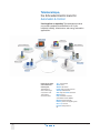

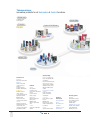

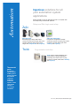
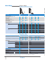
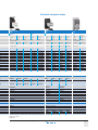

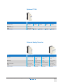
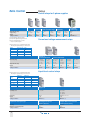
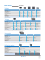
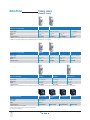
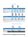
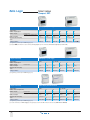
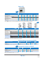
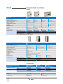
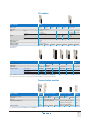
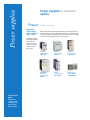
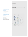

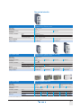
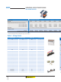
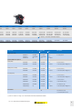
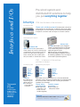
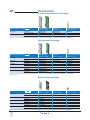
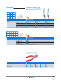
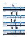
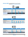
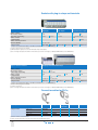
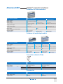
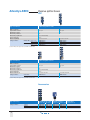
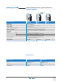
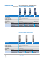
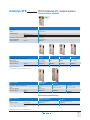
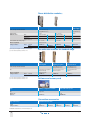
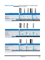
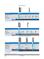
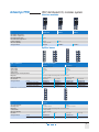
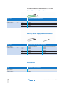
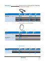
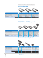

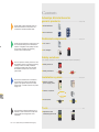
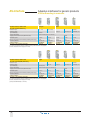
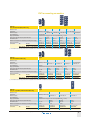
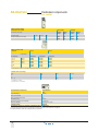

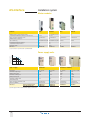
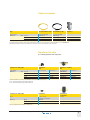
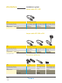
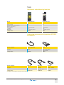


![Manuel installation plaque de cuisson in[...]](http://vs1.manualzilla.com/store/data/006114126_1-882d4753e6fe658c3c2e0b8b458faeca-150x150.png)